HAL Id: tel-00079240
https://tel.archives-ouvertes.fr/tel-00079240
Submitted on 10 Jun 2006HAL is a multi-disciplinary open access archive for the deposit and dissemination of sci-entific research documents, whether they are pub-lished or not. The documents may come from teaching and research institutions in France or abroad, or from public or private research centers.
L’archive ouverte pluridisciplinaire HAL, est destinée au dépôt et à la diffusion de documents scientifiques de niveau recherche, publiés ou non, émanant des établissements d’enseignement et de recherche français ou étrangers, des laboratoires publics ou privés.
Spin-transfer effects in spin-valves for CPP-GMR heads:
A static and dynamic investigation
Alina Deac
To cite this version:
Alina Deac. Sptransfer effects in spvalves for CPP-GMR heads: A static and dynamic in-vestigation. Condensed Matter [cond-mat]. Université Joseph-Fourier - Grenoble I, 2005. English. �tel-00079240�
Spin-transfer effects in spin-valves for CPP-GMR heads:
A static and dynamic investigation
by
Alina Maria Deac
Thesis submitted to the Joseph Fourier University (Grenoble) for the degree of Doctor of Philosophy
June 2005
Thesis advisors: Defence jury:
Jean-Pierre Nozières Jacques Miltat (referee)
Bernard Dieny Alain Schuhl (referee)
Olivier Redon Peter Levy
Henri Jaffrès Joël Cibert
Laboratoire de Spintronique et Technologie des Composants (Spintec), and Laboratoire d’Electronique de Technologie de L’Information (Léti)
To the memory of my father, who showed me how to make strawberry ice-cream with liquid nitrogen when I was still in kindergarten,
and to my mother, who taught me to never give up.
Acknowledgements
I would like to express my gratitude to all the people who helped me during my thesis: My three PhD advisors, for everything I learned from them, scientifically but not only, and for letting me do things my way:
- Jean-Pierre Nozières, my official PhD advisor, for his diplomatic touch, his optimism and energy and all the problems he has solved;
- Olivier Redon, my other PhD advisor, for having accepted me as his first PhD student (hopefully the experience didn’t prove completely discouraging for the future…though one never knows), for introducing me to thin layers magnetism and measurements, for motivating me and reading my “chef d’oeuvre” through and through;
- Bernard Dieny, my un-official PhD advisor, for having always been there for me – for scientific discussions and more. Merci, Bernard, for all the things you taught me, for your constant interest in my work, for your moral support during conferences and other difficult times, and for many the other things, including a beautiful drive on the 101 and showing me San Francisco.
Jacques Miltat and Alain Schuhl for having accepted to referee my thesis (all 200 pages of it!), and Peter Levy, Henri Jaffres and Joel Cibert, for taking part in the defense jury; The people from Headway for making (and sending me) the samples: Yue Liu, Min Li, Pokang Wang;
Pierre Gaud, director of LCMI, the group where I started my thesis and which has since split in several laboratories (among which LMNO), for being such a good mediator; Xavier Hugon, director of LMNO, for his constant support;
Jean-Eric Wegrowe, for his hospitality at the Ecole Polytechnique in Paris, for his honesty, humor and good will, for all his efforts in helping me with the experiments and for unforgettable dinners at the ‘Crocodile’;
Claude Chappert and Thibault Devolder, for offering me the chance of measuring at the Institut D’Electronique Fondamentale in Paris;
All the people at Spintec who helped me in various ways:
- Kyung-Jin Lee for spin-torque micromagnetic simulations;
- Anatoly Vedyaev (quit smoking, Anatoly!), Natalia Ryzhanova and Nikita Strelkov for discussions on spin-torque theory and CPP-GMR calculations;
- Sebastien Petit (Seb, if you’re the one to inherit my beloved samples, I’ll sleep easily knowing they are in good hands…), Dana Stanescu, Ricardo Sousa, Stephane Auffret, Christophe Tirion and Ursula Ebels for helping me with the experiments;
- Catherine Broisin, the super-secretary who always finds a way;
- all my other colleagues for their moral support, interesting and enlightening discussions on unspeakable topics, coffee breaks, dining out, going dancing (for the braver ones…) and so on.
People from the old LCMI:
- Monique Drevon, the other super-secretary;
- Marie-Helene Vaudaine, for introducing me to clean-room techniques;
- Bernard Viala, Marcel Audoin, Line Vieux-Rochaz and Venceslass Rat for their friendship;
All my friends, for still being my friends after various horrible times; All the people I forgot but should have mentioned;
My family, for love and understanding;
Foreword
The research related to spin-torque phenomena is one of the “hottest” topics in magnetism these days, at least going by the number of publications and international conferences on the subject. Although the physics of these effects is still not completely understood, it is already clear that the applications would be of major importance. The first studies have investigated current induced magnetization switching, motivated by the perspective of using it as a new writing scheme for MRAMs. Precessional states induced by the current, demonstrated less than two years ago, may constitute the working principle for new RF oscillators, interesting for telecom applications. Consequently, though the research in this field remains pretty fundamental, all the big microelectronics companies (such as Sony, Toshiba, Hitachi, IBM, Seagate…) are getting involved in this topic, considering the foreseen applications of spin-transfer in computer industry, wireless communication and so on.
To-date, spin-transfer phenomena have been analysed in detail in simple Co/Cu/Co multilayers. Studying spin-transfer in very complicated spin-valves, containing exchanged biased synthetic antiferromagnetic laminated reference layers and laminated free layers of considerable thickness, has brought another point of view on the matter and put forward several interesting new observations.
On the other hand, this study was particularly timely not only for applications such as MRAM or RF components, but also considering the importance of spin-transfer effects in CPP-GMR heads for hard disk drives. The magnetic read-head industry expects to be able to push forward the CIP head technology for about two years longer, after which it should probably move on to the CPP geometry. By then, parasitic effects induced by spin-transfer must be under control in these devices.
This thesis is divided into two main parts: part A gives an introduction to CPP-GMR and spin-transfer (through theoretical models, simulation results and experimental studies); part B presents spin-transfer in spin-valves for CPP-GMR heads, including a
brief motivation, descriptions of the experimental setups and sample fabrication procedure, results of static and dynamic measurements and an analysis of the influence of the laminating material on the CPP-GMR and the switching currents. A possible structure for microwave oscillators devices based on spin-current induced effects is proposed in the last chapter.
Avant-propos
En considérant le nombre de publication et de conférences internationales sur le sujet, le transfert de spin est aujourd’hui une des thématiques les plus florissantes et probablement les plus porteuses aussi.
Même si on ne comprend toujours pas complètement la physique de ces effets, il est déjà évident que leurs applications seront de première importance. En effet, la plus part des études antérieures concernaient le renversement par courant polarisé, qui pourrait être utilisé comme nouvelle méthode d’écriture dans les mémoires magnétiques (MRAM). Plus récemment, la precession entretenue induite par le transfert de spin a été proposé comme principe de fonctionnement pour un nouveau type d’oscillateur RF pour les télécommunications mobiles. Vu l’importance que ces applications pourraient avoir dans l’industrie des ordinateurs, télécommunications sans fil, etc., toutes les grandes compagnies en microélectronique (Sony, Toshiba, Hitachi, IBM, Seagate, Freescale…) financent des études sur les effets de transfert de spin. Néanmoins, la recherche dans le domaine reste en général assez fondamentale.
Jusqu’à présent, les phénomènes induits par le transfert de spin ont été analysés en détail dans de multicouches simples de type Co/Cu/Co. L’étude (présenté ici) de ces effets dans des vannes de spin complexes, contenant des couches de référence synthétiques laminées et piégées par échange et des couches libres laminées aussi et d’épaisseur considérable a amené un point de vue différent sur le sujet et a permis de mettre en évidence plusieurs aspects inattendus.
Cette étude a été particulièrement opportune considérant l’évolution du marché des têtes de lecture magnétorésistives : on s’attend à pouvoir exploiter la technologie actuelle (basée sur des vannes de spin dans lesquelles on applique un courant dans le plan des couches) jusqu’à 2007. Ensuite, on prévoit de passer en géométrie CPP (où le courant est perpendiculaire aux interfaces). Il est donc souhaitable de trouver des moyens de contrôler le bruit induit par le transfert de spin dans ces structures avant cette date.
Ce mémoire de thèse est divisé en deux grandes parties : la première (A) est une introduction sur le sujet (à travers des études théoriques, simulations micromagnétiques
et résultats expérimentaux principalement dans des échantillons Co/Cu/Co) ; la deuxième partie (B) concerne le transfert de spin dans les vannes de spin pour têtes CPP-GMR. Elle inclut des descriptions des échantillons, du banc de mesure et de la procédure de fabrication, des résultats des mesures statiques et dynamiques et une analyse de l’influence du matériau de lamination sur la GMR et les courants de renversement. Finalement, une structure possible des oscillateurs RF basés sur le transfert de spin est proposée dans le dernier chapitre.
Part A :
Chapter 1.
Current - perpendicular - to - plane giant
magnetoresistance
The results presented in this thesis have been obtained studying metallic pillars, explicitly spin-valves developed for current-perpendicular-to-plane (CPP) giant magnetoresistance (GMR) heads. Spin-transfer effects are usually studied in metallic multilayers containing two ferromagnetic films, one fixed, and the second free to be oriented parallel or antiparallel to the first one. The orientation of the free layer’s magnetization can be changed either under the effect of a magnetic field, or by applying a spin-polarized current. The resistance of the multilayer in the two states is different, which is the essence of the GMR phenomenon. Therefore, the GMR signal can be used to probe the switching of the free layer. Moreover, CPP-GMR and spin-transfer effects are strongly related through current polarization and spin accumulation effects. A good understanding of GMR mechanisms is therefore essential for the analysis of spin-torque induced effects.
A.1.1.
Simple intuitive GMR model
In ferromagnetic transition metals (such as Co, Fe, Ni or their alloys) the electrons which participate to the conduction of the current are s, d and hybridized sd. According to the orientation of the projection of their spin along the magnetization of the layer (parallel / antiparallel), two types of conduction electrons can be distinguished: spin up ( ↑ ) and spin down ( ↓ ), also called “majority” and “minority” carriers.
A characteristic of these metals is the d-band exchange splitting [1]. For a hard ferromagnetic material such as cobalt, for example, the spin up d sub-band is completely filled, and the d states at the Fermi level contain only spin down electrons (Fig. A.1.1). The main consequence of the exchange splitting is that the majority and minority carriers have very different scattering rates, regardless of the nature of the scattering centres (magnetic impurities, phonons, structural defects…), because the densities of available states into which the electrons can be scattered are very different.
In the case of cobalt, scattering will affect more the spin down electrons, while the spin up electrons see a very low resistivity and carry most of the electrical current. This
implies that an electrical current crossing a ferromagnetic material can gain a spin polarization.
Fig. A.1 - 1 Schematic representation of the electronic structure in the case of cobalt. N(E) is the density of states for the s and d majority and minority electrons. The d states at the Fermi energy εF contain only spin down electrons.
At temperatures considerably lower than the Curie temperature, spin-flip scattering events are negligible and spin up and spin down electrons carry the electrical current in parallel. This is the so-called “two-current model” [2]. For ferromagnetic transition metals at low temperature this hypothesis is justified, since the spin-orbit coupling is weak and magnon scattering is negligible under these conditions. Therefore, if ρ↑ and ρ↓ are the resistivities seen by the two currents, the resistivity of the
ferromagnetic material can be written: ↓ ↑ ↓ ↑ + ⋅ =
ρ
ρ
ρ
ρ
ρ
(1) At higher temperatures, however, spin-flip scattering must be considered. When electrons pass from one conduction channel to the other, the resistivity of the material can be determined as [3]:(
)
↑↓ ↓ ↑ ↓ ↑ ↑↓ ↓ ↑ + + + ⋅ + ⋅ =ρ
ρ
ρ
ρ
ρ
ρ
ρ
ρ
ρ
4 (2)The GMR effect can be easily understood using the two-current model described above. Consider the simplest structure where this effect is present - a trilayer containing
two magnetic layers (like cobalt) separated by a non-magnetic spacer (like copper). In the parallel configuration, spin up electrons are weakly scattered in both magnetic layers, and can carry a lot of current (Fig. A.1 - 2). Similarly, spin down electrons are strongly scattered, and participate less to the conduction. In the antiparallel configuration, the majority spins in one layer become minority spins in the second, and vice-versa. If r (R) is the resistance of a magnetic layer for majority (minority) spins, and neglecting the resistance of the non-magnetic spacer, as well as spin-flip scattering, the equivalent resistance of the multilayer in the two configurations can be written (see Fig. A.1 - 2): 2 2 1 2 1 1 R r R R r R AP P + = + = (3)
FM
NM
FM
FM
NM
FM
FM
NM
FM
FM
FM
FM
NM
NM
NM
FM
FM
FM
r
r
R
R
r
r
R
R
r
r
R
R
r
r
R
R
Fig. A.1 - 2 Two-current model in a Co/Cu/Co multilayer, for the parallel (left) and antiparallel (right) alignment between the magnetizations of the two layers. If r (R) is the resistance of a Co layer for the spin up (spin down) electrons, the resistance of the multilayer in each configuration can be calculated using the equivalent circuit below.
The GMR amplitude is defined as the variation of the resistance between the two configurations, normalized by the resistance of one of the states, for example P:
P P AP R R R GMR= − (4)
Introducing α =ρ↑/ρ↓ = r/R, it can be shown that:
(
)
α α 4 1− 2 = ∆ = P R R GMR (5)Although the above formula (5) is valid both for CIP (current in plane) and CPP-GMR, the scaling lengths in the two geometries are very different. For the CIP configuration, classical [4] as well as quantum models [5] showed that electrons average the properties of the multilayers in the perpendicular-to-plane direction on the length scale of the electron mean free path (MFP) λ. The CIP-GMR vanishes when the period of the multilayer (i.e. the thickness of the layers) becomes much larger than MFP, since electrons see each magnetic layer independently. In the CPP configuration, electrons cross all layers and thus the relevant scaling parameter is the spin diffusion length (SDL) lsf. For layers thinner than SDL, spin-flip scattering is negligible and the spin up
and spin down conduction channels can be regarded as independent [6]. In most cases,
lsf is much larger than λ.
In addition to spin-dependent scattering phenomena previously discussed, the lattice potential modulation plays an important role for the GMR effect [7]. The potential seen by the electrons includes an intrinsic part due to the spin-dependent modulation of the potential in the multilayer, and an extrinsic contribution caused by interface or bulk defects which induce spin-dependent scattering (Fig. A.1 - 3).
The spin-dependent modulation of the lattice potential is the result of the difference in the positions of the bottoms of the conduction bands with respect to the Fermi energy in neighboring layers. In the case of Co/Cu multilayers, for instance, the matching of the conduction bands is very good for the majority electrons, so that spin up carriers encounter a nearly flat potential through the whole structure. On the other hand, a strong mismatch exists in the case of spin down electrons, resulting in large potential steps at the interfaces. Lattice potential modulations cause spin-dependent reflection and refraction of the electrons at the interfaces.
Although this image is valid both for CIP and CPP geometries, the roles played by lattice modulations in the two cases are very different [8]. For CIP, in the P configuration, minority electrons which propagate within the Cu layers bounce back and
forth between the two Co/Cu interfaces and remain confined in these layers, while flowing along the electric field. In the CPP geometry, the field is perpendicular to the interfaces and electrons are forced to pass the potential steps, resulting in additional spin-dependent interfacial resistance [9].
Fig. A.1 - 3 Potential landscape seen by the majority and the minority electrons in a Co/Cu multilayer. The intrinsic potential is represented by a periodic array of barriers; the extrinsic bulk and interface spin-dependent scattering potentials are represented by spikes. (Extracted from ref. 7)
The following paragraph concentrates on describing the specific mechanisms of CPP-GMR, since this is the important geometry for spin-transfer.
A.1.2.
CPP-GMR and Valet-Fert theory for metallic multilayers
As mentioned before, in the absence of spin-flip mechanisms, the transport properties of magnetic multilayers in the CPP configuration can be described through a
very simple two-channel resistor model. For each channel, the various layers are considered as carrying the current in series, and interfaces are taken into account as additional spin-dependent resistances. In a FM/NM/FM multilayer, the resistivity for the spin up and spin down channels in the bulk of the layers can be written as:
ρFM↑
( )
↓ =2ρ*FM[
1−(+)β]
ρNM↑( )
↓ =2ρ*NM (6) where β is a coefficient describing the bulk spin scattering asymmetry in the FM layer.*
FM
ρ and ρ*NM are related to the measurable resistivities ρFM and ρNM trough the
following expressions:
ρFN =ρ*FN
(
1−β2)
ρNM =ρ*NM (7)
Similarly, if RFM/NM is the resistance of an interface (which can be determined
experimentally) the interfaces can be described using an interfacial spin scattering asymmetry coefficient γ:
RF↑
( )
/↓NM =2RF* /NM[
1−(+)γ]
RF/NM =R*F/NM
(
1−γ2)
(8) Both β and γ take values between -1 and 1, depending on the material. Since the resistance of a homogeneous pillar of section A varies as the resistivity times the thickness of the pillar divided by A, it is common to express the CPP resistance in terms of resistance×area product. This allows for the description of the intrinsic properties of the material independently of geometrical considerations.Table A. 1-1 gives an overview of the values obtained for CPP parameters to-date. A wide spread is observed in the results published by different groups, since they used different deposition techniques and therefore obtained layers with different microstructures and defects. However, some general trends can still be deduced. For example, scattering asymmetry at the Co/Cu interface (γCo/Cu) is larger than in than in
bulk Co (βCo). In contrast, NiFe seems to have comparable scattering asymmetry in the
The serial resistance network model has been successfully used to explain a large number of results, obtained mainly at low temperature, in Co based multilayers with relatively thin layers [10]. However, strong deviations from this model were observed in NiFe based systems. Moreover, this model cannot explain the different magnetoresistive properties of multilayers in which the ordering of the layers was changed, for example interleaved (Co1nm/Cu2nm/Co6nm/Cu2nm)4 and separated
(Co1nm/Cu2nm)4/(Co6nm/Cu2nm)4. In the resistor model, the resistances of layers and
interfaces are additive, so changing the order of the layers should not alter the result.
4.3 ± 1 5.5 59 ± 18 140 ± 20 0.8 ± 0.1 0.70 0.54 0.8 ± 0.1 0.73 26.3 15.9 0.55±0.07 0.85 ± 0.10 0.50 ±0.09 0.71 ± 0.02 0.71 ±0.05 0.3-1.1 0.30 ± 0.05 0.25 ±0.04 0.43 ± 0.04 0.38 ±0.03 0.46 ± 0.05 0.36 ± 0.04 0.27 ±0.03 0.48 ± 0.04 0.38 ±0.6 51-57 18 ± 2 4.2±0.7 3.0 ± 0.6 6.6 ±0.5 1.3-3.3 3.1 0.39±0.07 1.3 ± 0.3 0.6 ±0.1 Electrodeposited nanowires Doudin, 1996 20K Electrodeposited nanowires Piraux, 1996 77K Grooved substrates Oepts, 1996 4.2K MBE grown multilayers List, 1995 4.2K Sputtered multilayers 4.2K (MSU) Bass, 1999 4.2K ) . ( * cm Cu µΩ ρ ) . ( * cm CoµΩ ρ Co
β
) . ( 2 * / m m ARCoCu Ωµ Cu Co/γ
) . ( * cm NiFeµΩ ρ NiFeβ
) . ( 2 * / m m ARNiFeCu Ωµ Cu NiFe/γ
)
(nm
l
sf Cu)
(nm
l
sf Co)
(nm
l
sf NiFe 4.3 ± 1 5.5 59 ± 18 140 ± 20 0.8 ± 0.1 0.70 0.54 0.8 ± 0.1 0.73 26.3 15.9 0.55±0.07 0.85 ± 0.10 0.50 ±0.09 0.71 ± 0.02 0.71 ±0.05 0.3-1.1 0.30 ± 0.05 0.25 ±0.04 0.43 ± 0.04 0.38 ±0.03 0.46 ± 0.05 0.36 ± 0.04 0.27 ±0.03 0.48 ± 0.04 0.38 ±0.6 51-57 18 ± 2 4.2±0.7 3.0 ± 0.6 6.6 ±0.5 1.3-3.3 3.1 0.39±0.07 1.3 ± 0.3 0.6 ±0.1 Electrodeposited nanowires Doudin, 1996 20K Electrodeposited nanowires Piraux, 1996 77K Grooved substrates Oepts, 1996 4.2K MBE grown multilayers List, 1995 4.2K Sputtered multilayers 4.2K (MSU) Bass, 1999 4.2K ) . ( * cm Cu µΩ ρ ) . ( * cm CoµΩ ρ Coβ
) . ( 2 * / m m ARCoCu Ωµ Cu Co/γ
) . ( * cm NiFeµΩ ρ NiFeβ
) . ( 2 * / m m ARNiFeCu Ωµ Cu NiFe/γ
)
(nm
l
sf Cu)
(nm
l
sf Co)
(nm
l
sf NiFeTable A.1 - 1 CPP-GMR parameters determined experimentally by different groups using different deposition techniques [11]. All the experiments have been performed at low temperature. (Extracted from ref. 8).
It has been demonstrated that the different behavior of the interleaved and separated Co/Cu multilayers is due to the fact that in the AP configuration, the up and down orientations of the magnetizations alternate for interleaved stacks, while separated
multilayers organize so that half of the stack is up and the other half is down, neighboring layers being oriented in the same direction within each half of the stack. The deviations from the simple resistor network model can be explained by taking into account spin accumulation and spin relaxation effects [6].
Spin accumulation can be understood considering an interface separating two magnetic semi-infinite layers oriented antiparallel to each other. Suppose a current is flowing from right to left (i.e. electrons are drifting from left to right), and that spin ↑ electrons are less scattered than spin ↓ (β >0). For simplicity, the magnetization is assumed parallel to the spin of the majority electrons. In the left ferromagnetic layer, far from the interface, the current is mainly carried by spin ↑ electrons. If J is the total current density through the multilayer, the currents carried by the two spin channels are: ↑ =
(
1+β)
2 J j ↓ =(
1−β)
2 J j (9) In the right ferromagnetic layer, the magnetization is oriented in the opposite direction and the roles of spin ↑ and spin ↓ electrons are inverted. More spin ↓ electrons flow away from the interface than spin ↑. Therefore, within each spin channel, there is a clear unbalance between the numbers of electrons moving towards the interface in the left layer and away from the interface in the right layer, per unit time (Fig. A.1 - 4). Consequently, there will be a local excess of spin ↑ electrons and a correlated local deficit in spin ↓ carriers around the interface.In steady state, spin accumulation does not increase with time, being counterbalanced by spin flip processes, such as spin orbit and magnon scattering. The characteristic length scale over which spins maintain their orientation in a given material is the spin diffusion length lsf , related to the spin-flip relaxation time τsf via :
( )
2( ) ( )
2 2 1 1 1 ↓ ↑ + = l l lsf (10) where the ) (↓ ↑ l are given by :(
)
2 / 1 ) ( ) (↓ =31 ↑ ↓ ↑ vF sf l λ τ (11)In equation (11), νF is the Fermi velocity, and λ↑(↓) are the elastic MFP. Low
temperature values of SDL in commonly used materials are given in Table A.1-1.
The equilibrium between spin accumulation and spin relaxation leads to local variations in the difference ∆µ between the electrochemical potential of spin up and spin down electrons (Fig. A.1 - 4). Therefore, a small non equilibrium local magnetization, proportional to the current, appears near the interface.
Fig. A.1 - 4 Electrochemical potential (top) and spin current densities (bottom) versus z for an isolated interface separating two semi-infinite domains with opposite magnetizations. The arrows represent the magnetization of the layers and z is the direction of the current (perpendicular to the plane of the layers). It is assumed that for both layers spin up electrons are less scattered than spin down (β> 0). ∆µ > 0 implies an accumulation of spin up electrons at the interface. The gradient of the spin current expresses the spin relaxation which takes place on the scale of the SDL on each side of the interface. Spin accumulation reduces the current asymmetry and increases the electric field over a length of the order of SDL on both sides of the interface, which adds an interface resistance of the order of ρ*lsf. (Extracted from ref. 6 and 8).
Starting with a Boltzmann equation model, Valet and Fert calculated the transport properties of magnetic multilayers for the CPP configuration, taking into account both volume and interface spin-dependent scattering. When SDL >> MFP, this model can be reduced to a macrospin approach, based on two basic equations:
(
)
( )
2 * 2 sf l z j eρ σ =− µσ −µ−σ ∂ ∂ z e j ∂ ∂ = σ σ σ µ ρ 1 (12) where e is the absolute value of the electron charge, σ is the spin ( ↑, ↓ ) and the resistivities ρ* andρσ are given by eq. (6) and (7). The first equation describes spin relaxation effects, whereas the second is a generalized form of Ohm’s law.It can be shown that ∆µ obeys a simple diffusion equation within each layer. The general solution of this equation is of the type:
− + = ∆ sf sf l z B l z Aexp exp µ (13)
The coefficients A and B can be determined from boundary conditions at the interfaces, which impose the continuity of the current for each spin channel, in the presence of spin-dependent interfacial resistance:
jσ(z =z0+)− jσ(z= z0−)=0 (14) (The interface is considered to be located at z =z0.) Moreover, if significant spin scattering occurs in an interfacial zone of surface A which is considered to be infinitesimal thin, the electrochemical potential must fulfill the equation:
(z = z0)− (z= z0)= AR ej (z = z0)
−
+ σ σ σ
σ µ
µ (15)
Using these formulae, it is possible to calculate the spin accumulation, spin currents, CPP resistance and magnetoresistance of any magnetic multilayered stack, taking into account spin-flip processes [13]. Fig. A.1 – 5 shows the calculated spin accumulation and spin currents for a multilayer containing two ferromagnetic layers alternating with nonmagnetic layers, for both configurations possible (P and AP). The thickness of the magnetic (nonmagnetic) layers is tFM (tNM).
Considering the model of Valet and Fert, the failure of the simple resistor network to explain the CPP-GMR of NiFe based multilayers and the different behavior of separated and interleaved multilayers can be understood in terms of spin relaxation effects. In both types of systems, the length scale over which electrons propagating perpendicular to the plane experience a change from up magnetization to down magnetization is of the order of SDL, which is not longer than the thickness of the layers. Therefore, the assumption of simply additive resistances is incorrect.
Fig. A.1 - 5 Spin accumulation ∆µ (a, c) and spin up and spin down current densities for a magnetic multilayer (F tFN / NM tNM) with an infinite number of repeats, for the case β > 0.
(a) and (b) are calculated for the antiparallel alignment between the two magnetizations, (c) and (d) for the parallel geometry. (Extracted from ref. 6).
It is important to note that the Valet and Fert model only takes into consideration the case of collinear magnetizations in the multilayer. When that is not the case, non-diagonal terms have to be considered in the spin tensors, giving rise to new phenomena.
Resumé :
Généralement, les effets de transfert de spin sont étudiés dans des multicouches métalliques dans lesquelles le courant est appliqué dans la direction perpendiculaire au plan des couches. Dans ces structures, l’aimantation d’une première couche (nommée ‘couche libre’) peut être orientée parallèlement ou antiparallèlement par rapport au moment magnétique d’une deuxième (appelée ‘couche piégée’), considéré comme fixe. L’orientation de l’aimantation de la couche libre peut être changée en appliquant soit un champ magnétique, soit un courant à travers la structure. La résistance de l’empilement est différente dans le deux états : ce phénomène est connu sous le nom de ‘magnétorésistance géante’ (GMR). La GMR peut dont être utilisée comme sonde pour connaître l’état de la couche libre. En plus, ce phénomène et le transfert de spin sont corrélés à travers la polarisation du courant et les effets d’accumulation de spin. En conséquence, une bonne compréhension des mécanismes de la GMR est nécessaire pour l’analyse des effets induits par le transfert de spin.
Ce chapitre offre une courte description de la magnétoresistance géante. Un premier modèle, simple et intuitif, décrit le multicouche métallique comme un réseau de résistances connectées en série, à travers lesquelles les deux types d’électrons (spin up et spin down) transportent le courant en parallèle. Dans toute couche magnétique, les résistances vues par les électrons spin up et spin down sont différentes.
Un deuxième modèle plus élaboré, introduit par Valet et Fert, permet d’expliquer les détails de ce phénomène en prenant en compte des effets d’accumulation et relaxation de spin.
References :
[1] E.C. Stoner, Proc. Royal Soc. A165, 372 (1938)
[2] N.F. Mott and H.H Wills, Proc. Royal Soc. A156, 368 (1936) [3] A. Fert and I.A. Campbell, J. Phys. F 6, 849 (1976)
[4] R.E. Camley and J. Barnas, Phys. Rev. Lett. 63, 664 (1989) J. Barnas et al., Phys. Rev. B 42, 8110 (1990)
[5] P.M. Levy et al., Phys. Rev. Lett. 65, 1643 (1990) A. Vedyaev et al., Phys. Lett. A 198, 267 (1995) [6] T. Valet and A. Fert, Phys. Rev. B 48, 7099 (1993) [7] C. Vouille et al., Phys. Rev. B 60, 6710 (1999) [8] “Spin electronics“, edited by M. Johnson [9] A. Vedyaev et al., Phys. Lett. A 198, 267 (1995)
J. Barnas and A. Fert, J. Magn. Magn. Mat. 136, 260 (1994) [10] W.P. Pratt Jr. et al., Phys. Rev. Lett. 66, 3060 (1991)
S.F. Lee et al., Phys. Rev. B 46, 548 (1992)
S.F. Lee et al., J. Magn. Magn. Mat. 118, L1 (1993)
[11] J. Bass and W.P. Pratt Jr., J. Magn. Magn. Mat. 200, 274 (1999) W. Oepts et al., Phys. Rev. B 53, 14024 (1996)
N.J. List et al., J. Magn. Magn. Mat. 148, 342 (1995) L. Piraux et al., J. Magn. Magn. Mat. 159, L.287 (1996) B. Doudin et al., J. Appl. Phys. 79, 6090 (1996)
[12] S. Zhang and P.M. Levy, J. Appl. Phys. 69, 4786 (1991) [13] N. Strelkov et al., J. Appl. Phys. 94, 3278 (2003)
Chapter 2.
(Some) Spin-transfer theory
As explained before, the GMR effect illustrates the fact that the different relative orientations of the magnetic layers affect the electrical current, so that different configurations correspond to different measured resistances of the multilayer. The reciprocal phenomenon, that a spin-polarized current can transfer spin angular momentum to the magnetization of a layer and therefore alter its magnetic state, has also been demonstrated. This effect has been the object of intense study during the last few years, both theoretically and experimentally. Several numerical simulations have also been published. This chapter aims at an introduction to the theory of spin-transfer. The next chapters give an overview of numerical simulations and experimental studies in this field.
Theoretical works on spin-transfer can be divided in three categories [1]: 1. Models focusing on deriving and solving classical equations of motion for the magnetization under the effect of spin polarized current [2]. These studies generalize and solve the Landau-Lifshitz-Gilbert equation to take into account spin currents, spin accumulation and the mechanical torques generated by the transfer of spin angular momentum between current and magnetization.
2. Models generalizing charge transport theory to take account of spin currents and spin relaxation effects [3]. Using phenomenological methods or quantum mechanical formalisms (Boltzmann, Kubo or Landauer), these theories determine the spin-transfer torques that serve as input to the magnetization calculations.
3. Models which compute from quantum mechanical considerations various parameters that are used by the transport theories [4].
On the other hand, the early theories considered transport through the multilayer either as a purely ballistic [5] (A.1.2) or purely diffusive [6] problem (A.1.3). More recent models [7] regard transport as diffusive in the bulk of the layers and diffusive and / or ballistic at the interfaces.
A.2.1.
Model structure
The essence of spin-transfer induced effects is that a spin polarized current entering a ferromagnetic layer exerts a torque on its magnetization. Consequently, it can generate magnetic excitations, and even flip the magnetization of a given domain under certain conditions.
The model structure used to study this effect contains two magnetic layers, separated by a non-magnetic spacer (Fig. A.2 – 1). Both magnetic layers are considered as single domains. Their moments are supposed to be oriented at an angle θ relative to each other (where θ ≠ 0, π, or else, no torque is exerted).
Polarizing layer Free layer
Conduction electrons
Polarizing layer Free layer
Spin-torque
Polarizing layer Free layer
Conduction electrons
Polarizing layer Free layer
Spin-torque
Fig. A.2 - 1 Model structure for the study of spin-transfer. The spin-torque exerted on the magnetization of the free layer is drawn for the case when the current is applied so that the electrons flow from the polarizing to the free layer. On the left and the right part of the stack there are two non-magnetic conducting leads.
One of the magnetic layers should be thicker than the other, for two reasons: 1. This layer should be thick enough to induce a considerable spin polarization of the current;
2. Since spin-transfer is essentially an interfacial effect, occurring mainly on a characteristic length scale of about 1 nm from the interface, spin-transfer effects are more important in a thin layer than in a thick one. Consequently, by associating a thin and a thick layer, the latter can be considered as a reference layer with fixed magnetization, whereas the orientation of the moment of the thinner layer will be influenced by spin-transfer.
The role of the spacer is to decouple the ferromagnetic layers. Its thickness should be small compared to SDL, so that the spin polarization gained by the current while crossing the polarizing layer is mostly transmitted to the free layer.
The current is applied perpendicular to the plane of the layers. On each side of the magnetic multilayer there is a non-magnetic conducting lead.
A.2.2.
Mechanisms of spin-transfer
Inside a bulk ferromagnetic metal, Ohm’s law guarantees that the current is naturally polarized, the conductivities of majority and minority spin electrons being different. By the same argument, the current is obviously polarized in a non-magnetic metal, since spin up and spin down electrons have the same conductivities.
Suppose a current is applied through the model structure in fig. A.2 – 1 so that the electrons flow from the thick to the free layer. While crossing the thick magnetic layer, the current will acquire a spin polarization. When the spin polarized current reaches the interface between the non-magnetic spacer and the second magnetic layer, three different processes occur [8]:
1. Spin filtering: The reflection and transmission probabilities for up and down
electrons are spin dependent. The wave function for an electron with a non-zero spin component transverse to the magnetization can always be written as a linear combination of spin up and spin down components. The reflected and transmitted wave functions differ both from each other and from the incident state. This unavoidably leads to different transverse spin components and thus to a discontinuity in the transverse spin current. This is a one-electron effect that operates independently for
each carrier.
2. Differential spin reflection: The spin of an electron generally rotates when it
is reflected or transmitted at the interface between a non-magnetic material and a ferromagnetic layer. The rotation is non-classical and its amount differs considerably for electrons with wave vectors from different portions of the Fermi surface. While summing over all conduction electrons, very little remains of the reflected transverse spin current. The cancellation effect on the transmitted spin current is less dramatic.
3. Differential spin precession: Due to exchange splitting, the electrons
transmitted into the ferromagnetic layer possess spin up and spin down components with the same total energy (Fermi energy), but with different kinetic energy and therefore different wave vectors. Consequently, each spin precesses in space as it propagates from the interface. The precession frequency varies noticeably over the Fermi surface. As they propagate into the ferromagnetic layer, a rapid dephasing of the transverse spin components of individual electrons occurs. Averaging on all the conduction electrons, the precessing spin current cancels within few lattice constants from the interface.
Through all the three processes mentioned above, the electrons lose transverse spin angular momentum. From the conservation law, it follows that the transverse angular momentum lost by the current is transmitted to the magnetic moment of the free layer. This can be expressed in terms of a torque acting on its magnetization. In other words, the origin of the torque is the angular momentum transfer and the origin of angular momentum transfer is the absorption of transverse spin current at the interface. Therefore, to a good approximation, the torque is proportional to the transverse component of the spin current. This assumption is generally accepted
to-date, and agrees with most models published, whether they consider purely ballistic or purely diffusive transport in the multilayer – or a mixture of the two.
A.2.3.
Ballistic theory: Slonczewski’s original model
In 1996, Slonczewski introduced the term “spin-transfer”, defining the interaction between a spin polarized current and a magnetic layer [9]. He calculated that for layers with a lateral size of the order of 100 nm, spin-transfer can dominate the Oersted field induced effects. In the same article, Slonczewski predicted that: “two new phenomena become possible: a steady precession driven by a constant current, and alternatively a novel form of switching driven by a pulsed current”. Needless to
say, both predictions have since been demonstrated experimentally.
Slonczewski appreciated that in magnetic multilayers incorporating very thin metallic spacers spin-transfer effects would be more easily measurable than in magnetic tunnel junctions, for two reasons:
1. A metallic spacer implies low resistance and therefore low Ohmic dissipation for a given current; since spin-transfer effects are proportional to the current, they would become detectable for current densities above 106 A/cm². In contrast, the current
densities which can be applied through magnetic tunnel junctions are most often too low to allow the observation of such phenomena.
2. The fundamental interlayer exchange coupling of RKKY type diminishes in strength and varies in sign as spacer thicknesses increases. Therefore, it is possible to find spacers which are thick enough (~ 4 nm) for the exchange coupling to be negligible, even though spin relaxation is too weak to significantly diminish the GMR. (In consequence, one can consider that no spin polarization is lost in the spacer).
Slonczewski considered a structure similar to the one in Fig. A.2 – 1, so that the conduction electrons flow from the polarizing to the free layer for the positive sense of the current, and in the opposite direction for the negative sense. He used the method of spin currents and momentum conservation widely employed in deriving the conventional exchange coupling, and made the following assumptions:
1. By conservation of angular momentum, the free magnetic layer reacts to the passage of the spin current by acquiring a change of classical momentum equal to the sum of the inward spin fluxes from both sides of the free layer;
2. The mean of spin-transfer averaged with respect to the direction of electron motion is equal to the total absorption of the expectation value of the transverse spin component of the electron incident on the free layer;
3. The thickness of the free layer is too great for appreciable tunneling of minority spins electrons; majority electrons are totally transmitted and the transport is considered to be ballistic;
4. The magnetic layers have the same band structure, but different thickness. With these assumptions, it is possible to describe mathematically the complete transfer of the transverse component of the incident electron spin to the local magnetization. As such, an electric current composed of preferentially polarized incident electrons generally induces a well-defined motion of the free layer’s magnetization.
The equations are solved in the WKB limit for a general value of θ. The off-diagonal nature of the spin wave matrix dictates that scattering from a ferromagnetic layer completely annihilates the component of the spin current perpendicular to its magnetization. Therefore, the transverse component of the angular momentum of
the spin current is transmitted to the magnetic moment of the layer. This can be expressed in terms of a mechanical torque acting on the moment of the ferromagnet. When the magnetizations of the two layers are collinear, the transverse component is zero and the torque is zero.
Fig. A.2 - 2 Bottom: Coulomb plus locally diagonalized exchange potential V↑ (↓ ) versus
position in the direction perpendicular to the plane of the layers in a multilayer including two ferromagnetic and three non-magnetic layers. Top: Vector diagram for the magnetizations of the two layers and their current-driven velocities. (Extracted from ref. 9.)
If n+ (n-) are the majority (minority) spin densities in the ferromagnetic material,
the polarizing factor P can be defined as: − + − + + − = n n n n P (16) The spin-transfer torque can be written:
[
(
x)
]
s st g I m m u At M e r r r h r − × × ⋅ ⋅ ⋅ ⋅ − = Γ ( ) 2 θ γ (17) where: e is the electron charge in absolute value;γis the gyromagnetic ratio;
Ms is the saturation magnetization of the free layer;
A is the surface of the layer, perpendicular to the direction of the current;
t is the thickness of the free layer;
mr is the unit vector parallel to the magnetization of the free layer; −urx is the unit vector parallel to the magnetization of the pinned layer.
g(θ) is a function of the polarization of the current and of the angle between the magnetizations of the two layers. In his initial article published in 1996, Slonczewski calculates g(θ) as: 2 / 3 3 4 ) cos 3 ( ) 1 ( 4 1 ) ( P P g θ θ + + + − = (18)
It is important to note that the dynamics is reversible with respect to the sign of the current. At the same time, the absolute value of the torque acting on the magnetization of the free layer is equal to that acting on the magnetization on the pinned layer. (The reflected minority electrons transfer back the spin to the thick layer.)
Polarizing layer Free layer
Conduction electrons I > 0
Polarizing layer Free layer
H > 0
x
y
z
Polarizing layer Free layer
Conduction electrons I > 0
Polarizing layer Free layer
H > 0
x
y
z
Fig. A.2 - 3 Coordinates system used: the magnetization of the polarizing layer is considered to be oriented along –x; the positive sense of the current is defined so that the electrons flow from the thick to the thin layer, along the z axis. This definition of positive field and current corresponds to the one used in Part B: Spin-transfer effects in spin-valves developed for CPP-GMR heads.
Equation (17) can be deduced from geometrical considerations. The counter-intuitive tendency for the magnetizations of the two layers to rotate in the same direction results from the angular momentum conservation in the pinned and free layers. It is this unique property of current-driven exchange that generates the novel magnetic dynamics.
The dynamics of the free layer’s magnetization under the effect of a magnetic field Hres (which includes external, anisotropy and Oersted fields and dipolar coupling)
and a current I can be described using a Landau-Lifshitz-Gilbert equation with a supplementary spin-torque term:
(
)
(
)
[
]
[
(
x)
]
s z z d x k res g I m m u At M e t m m α u u m H u H H m γ t m r r r r r r h r r r m r r − × × ⋅ ⋅ ⋅ ⋅ − ∂ ∂ × ⋅ + ⋅ ⋅ − ⋅ × − = ∂ ∂ ) ( 2 γ θ (19) where Hd = 4πMs is the demagnetizing field (in the direction perpendicular to the planeof the layers),
Hk is the uniaxial anisotropy, and
α is the Gilbert damping parameter.
The positive sense of the field is considered to be along -urx. From eq. (19), it is possible to determine the instability currents, that is, the currents that drive the magnetization out of a given stable state:
− + − = − k res d s AP P H H H g At M e I 2 ) 0 ( 2 α h + + = − k res d s P AP H H H g At M e I 2 ) ( 2 π α h (20)
Slonczewski calculated that magnetization precession with frequencies around 10 GHz can be induced by current around 106 A/cm². The switching currents were predicted to be of the order of 107 A/cm².
This theory has been extended [10] to combine ballistic and diffusive features (and take into account spin accumulation). The main difference from the fully ballistic model lies in the dependence of the torque on the entire structure of the multilayer, including the magnets and the non-magnetic leads.
A.2.4.
Diffusive theory: the model of Zhang, Levy and Fert
Among others [for example ref. 7] Zhang, Levy and Fert introduced a model including spin diffusion effects in the study of spin-transfer [11]. They solved the equation of motion of the spin accumulation in order to derive the torque acting on the
background magnetization. Spin dependent scattering (both bulk and interfacial) and spin accumulation have proved to be necessary for understanding the CPP-GMR (see Chapter 1). The main achievement of this model was to express spin torques in terms of the same parameters as used for interpreting giant magnetoresistance in the CPP geometry. Following the conventional treatment of CPP transport in magnetic multilayers, it can be assumed that the magnetization is uniform within each layer and changes discontinuously at the interfaces. The boundary conditions at the diffusive interfaces between two layers with noncollinear magnetizations impose that the spin accumulation experiences a jump proportional to the interface resistance. The spin currents are either continuous, if no interfacial spin-flip is considered, or discontinuous in the opposite case. Specular reflection at the interfaces can also be taken into account.
Considering a multilayer such as the model structure in fig. A.2 – 1, with the current flowing uniformly along the z direction, the linear response of the multilayer to an electrical field can be written as a spinor form:
z n D z E C j ∂ ∂ − ⋅ = ˆ ( ) ˆ ˆ ˆ (21)
where E(z) is the electrical field, and jˆ, Cˆ, Dˆ , and nˆ are 2×2 matrices representing the current, conductivity, diffusion constant, and accumulation at a given point. They can be written in terms of Pauli spin matrices:
C C I C r ⋅ + = ˆ σ ˆ 0 D D I D r ⋅ + = ˆ σ ˆ 0 (22) n n I nm r ⋅ + = ˆ σ ˆ 0 where 2n0 is the charge accumulation and nm
r
is the spin accumulation. If mr is the unit vector of the local magnetization, the spin polarization parameter β is defined as: Cr =β⋅C0⋅mr (23) A similar spin polarization constant β’ can be introduced for the diffusion constant: Dr =β'⋅D0⋅mr (24) If the densities of states are different for the spin up and spin down electrons, βand β’ are different. For a degenerate metal with Nˆ(εF) the density of states at the Fermi level, conductivity and diffusion constants are related through the Einstein relation:
Cˆ =e2Nˆ(εF)Dˆ (25) The interaction between the spin accumulation and the local magnetic moment is described as an exchange interaction:
Hint =−J⋅nrm⋅mr (26) With these definitions, and bearing in mind that only the component of the spin accumulation transverse to the local magnetization will influence the local moment, it is possible to show that the equation of motion of the magnetization under the effect of a spin polarized current can be written as:
m
(
res p)
a m(
m mp)
t m m α m b H γ t mr r r r r r r r r × × ⋅ ⋅ − ∂ ∂ × ⋅ + − × − = ∂ ∂ γ (27)where mrp is the unit vector parallel to the magnetization of the pinned layer and a and
b are coefficients determined by geometric and structural details of the multilayer.
Eq. (27) expresses the fact that the transverse spin accumulation produces two effects simultaneously:
1. Depending on the sense of the current, the spin-torque term a⋅mr×
(
mr×mrp)
,first introduced by Slonczewski, acts so as to increase or decrease the angle between the magnetizations of the two layers (in other words, depending on the sign of the current, the spin-torque acts as damping or antidamping);
2. The term b⋅
(
mr×mrp)
is the torque due to an effective field b⋅mrp, whichproduces a precessional motion around the magnetization of the polarizing layer, acting as if spin-transfer created an equivalent magnetic field on the free layer.
It is important to note that in eq. (27) the two terms appear on equal footing. Indeed, it has been estimated that although the effective field decreases much faster than the spin torque as the thickness of the layers is increased, both have the same magnitude at their maximum [12]. The coefficients a and b have to be calculated for each system in particular. To derive the effective field and the spin torque analytically, an oversimplified case has to be considered.
The following assumptions are made:
1. The thick ferromagnetic layer is assumed to be pinned and half metallic, so that the current is fully polarized (spin accumulation is neglected in the pinned layer);
2. The spacer is infinitely thin and no spin-flip scattering occurs in this region, so that the spin current is conserved across this layer; the leads are perfect paramagnets;
3. The characteristic times of transport phenomena are much shorter (fs to ps) than the characteristic time of magnetization motion (ns); therefore, the background magnetization can be assumed to be fixed on the transport time scale, so that the equations for magnetization dynamics and for spin accumulation can be decoupled;
4. Spin-dependent reflection at the interfaces can be neglected; 5. SDL is the same in both magnetic layers; one can introduce:
λsf = 2D0τsf (28) lsf = 1−ββ'⋅λsf (29)
a and b are determined by first calculating the spin accumulation at a position z in the free layer and then averaging it over 0 ≤ x ≤ t (where t is the thickness of the free layer):
⋅ − − = − J t J J B t e t e hja a J λ λ λ µ λ 2 2 cos 1 2 2 3 0 ⋅ = − J t J J B t e t e hja b J λ λ λ µ λ 2 2 sin 2 2 3 0
where j is the current density in the pillar, j = I/A,
a0 is the lattice constant,
µB is the Bohr magneton.
The characteristic decay length for the spin accumulation is defined as:
J hD
J = 2 0
λ (31) The above expressions for a and b are only valid in the limit λsf >> λJ. This
condition holds in the case of cobalt, for example, where λJ is of the order of 1 nm. λJ is
the characteristic length scale for spin accumulation in the direction perpendicular to the plane of the layers. At the interface, the spin accumulation has to adjust to the new magnetization direction. Both the longitudinal and the transverse components of the spin accumulation experience changes of the same order of magnitude; however, the distance over which the transverse component is absorbed, λJ (~ 1 nm) is much smaller
than that for the longitudinal spin accumulation lsf (~ 60 nm). Far from the interfaces, at
z >> λJ and z << -λJ, the spin current is collinear with either the magnetization of the
free layer or that of the polarizing layer, approaching the bulk values in the respective materials; for -λJ < z < λJ, a strong gradient is found in the transverse spin
accumulation, and it is this gradient that contributes to the spin-transfer. As a consequence, λJ is also the characteristic length scale for spin momentum transfer.
Similar calculations can be also performed if the approximation λsf >> λJ is no
longer valid, or for the more general case when the polarizing layer is not half metallic and taking into consideration spin-dependent reflection at the interfaces. Also, a more realistic analysis should treat the spin accumulation in the polarizing and the free layer in a self consistent manner. However, although the expressions for the two coefficients are more complicated in the general case, the oversimplified example above conveys the physical result of the diffusive model.
Different authors have applied this formalism to interfacial [13] (λJ ≈ 1 nm) and
non-interfacial [14] (λJ = 4 nm, for example) spin-transfer. The main difference
between the two limits is that in the case when purely interfacial spin-transfer is considered, the effective field term becomes much less important than the spin torque term. Experimental results have been interpreted as agreeing with one concept [12] or the other [15].
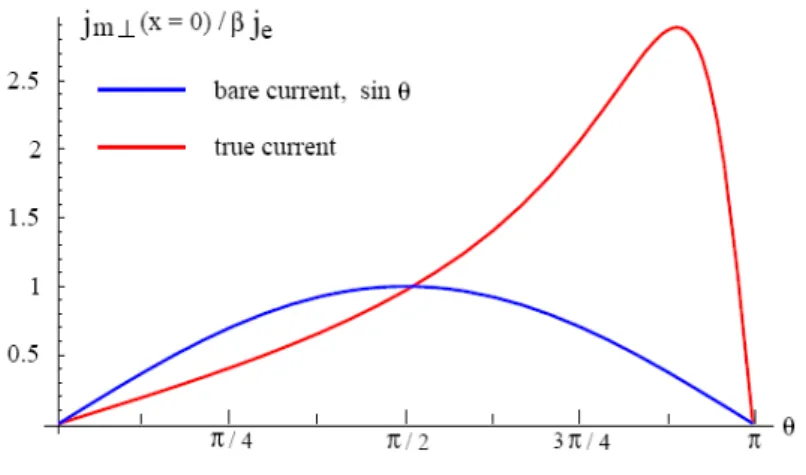
Whether considering the interfacial or the non-interfacial approach, when calculations are carried out taking into account the entire structure (including the current leads), it turns out that the spin angular momentum transferred from the polarized current to the background magnetization of the free layer far exceeds the transverse component of the bare portion of the incoming spin polarized current (Fig. A.2 – 4). This amplification is due to the large gradient of the transverse spin accumulation at the interface between the spacer and the free layer, which generates very strong local diffusion transverse spin currents. Fert et al. estimate this enhancement to be of the order of the mean value of SDL divided by MFP in all the structure, including the leads
( 〈 lsf / λsdl 〉) [13]. Shpiro et al. evaluate the amplification to be proportional to the ratio
of SDL to the characteristic length scale of the spin accumulation ( lsf / λJ ).
this amplification effect might be used in order to reduce the switching currents in view of spintronics applications.
Fig. A.2 - 4 True spin current at the interface between the spacer and the free layer (red line) in comparison with the bare transverse current (blue line) as a function of the angle between the magnetizations of the two layers, for λJ = 4 nm and lsf = 60 nm. (Extracted from ref. 10).
It is important to note that calculations considering diffusive transport find that there is a strong asymmetry between the spin-torque exerted on the free layer’s magnetization close to the P or AP configurations, similar to the ballistic model of Slonczewski. While in Slonczewski’s case the asymmetry was expressed through the dependence of the spin-torque on the function g(θ), in the diffusive limit the asymmetry is the result of the different values taken by transverse spin accumulation for different configurations.
A.2.5.
Magnetic temperature model
In order to account for the strongly incoherent dynamics observed experimentally at finite field when studying spin-transfer effects, S. Urazhdin [16] introduced a quantum model which describes the effect of a spin polarized current on the magnetization of a layer in terms of an effective magnetic temperature rather than a spin-torque. This model portrays current induced magnetization reversal as thermally
activated switching over a one-dimensional potential barrier, with an effective temperature Tm(I) which depends on the current. It was argued that Tm can differ from the lattice temperature Tph in confined geometry, where the magnetic energy relaxes significantly more slowly than the highly excited individual magnetic modes.
For a current I flowing through the pillar, TmP(I) ≠ TmAP(I). (The positive sense of
the current is defined so that the electrons flow from the polarizing to the free layer.) In the P state, for negative currents higher than a threshold value, magnetic excitations lead to an increase of TmP so that a thermally activated transition to AP occurs. For this
direction of the current, the conditions for magnetic excitations are not satisfied for the AP state, so the magnetic system cools back to the lattice temperature, and the AP state is stable. If then, for the same current, a field higher than the coercivity of the free layer is applied so that it favors the P state, the transition from the antiparallel to the parallel orientation can also be thermally activated, leading to telegraph noise. Similar behavior is expected when the current and the field are reversed.
Although the mechanisms are different for magnetic temperature and spin-torque models, the stability phase diagrams are very similar. Also, the actual switching dynamics may be the same, since thermally activated switching occurs through an almost deterministic optimal path, which can be very close to a coherent rotation.
A.2.6.
Important parameters
While several details concerning spin-transfer effects remain controversial and nut fully understood, the scientific community seems to have reached a consensus over several aspects of the problem:
A.2.6.a.
Sign of the torqueThe torque is proportional to the current density flowing through the multilayer, and it changes sign when the current is reversed. When the current is applied so that the
electrons flow from the polarizing to the free layer, the resulting torque tends to align the magnetization of the latter parallel to that of the former. If the current direction is reversed, the torque acts so as to bring the two magnetizations in the antiparallel state.
Fig. A.2 - 5 Top: When a positive current is applied, the electrons flow from the pinned to the free layer and the torque favors the parallel alignment between the magnetizations of the two layers. Bottom: The opposite sense of the current generates a torque that tends to bring the magnetization of the free layer to the direction antiparallel with respect to the moment of the thick layer.
A.2.6.b.
The decay lengthIt is mostly accepted that the transverse component of the spin polarized current is absorbed in a few atomic layers from the interface. The quantum mechanical analysis of Stiles and Zangwill [8], for example, finds that in general the spin-transfer takes place in the first nanometer of the free layer. Their calculations are restricted to Ohmic transport but should be valid for most metallic multilayers where layer thicknesses are less than the relevant mean-free paths. Shpiro, Levy and Zhang consider, however, that the decay length can be much longer (~ 5 nm) [14].