HAL Id: cea-02339458
https://hal-cea.archives-ouvertes.fr/cea-02339458v2
Submitted on 21 Oct 2020
HAL is a multi-disciplinary open access
archive for the deposit and dissemination of
sci-entific research documents, whether they are
pub-lished or not. The documents may come from
teaching and research institutions in France or
abroad, or from public or private research centers.
L’archive ouverte pluridisciplinaire HAL, est
destinée au dépôt et à la diffusion de documents
scientifiques de niveau recherche, publiés ou non,
émanant des établissements d’enseignement et de
recherche français ou étrangers, des laboratoires
publics ou privés.
Paolo Cattaneo, Frederic Damian, Jean-Charles Le Pallec, Elsa Merle, Didier
Schneider
To cite this version:
Paolo Cattaneo, Frederic Damian, Jean-Charles Le Pallec, Elsa Merle, Didier Schneider.
Development of a multiphysics Best-Estimate approach for LWR reference calculation .
ICAPP
2019 - International congress on advances in nuclear power plants, May 2019, Juan-Les-Pins, France.
�cea-02339458v2�
000254 Development of a multiphysics Best-Estimate approach for
LWR reference calculation
Paolo CATTANEO1*, Frederic DAMIAN2, Jean-Charles LE PALLEC1, Elsa MERLE4,
Didier SCHNEIDER3
1DEN, Service d’études des réacteurs et de mathématiques appliquées (SERMA),
2DEN, Département de modélisation des systèmes et structures (DM2S),
3DEN, Service de thermo-hydraulique et de mécanique des fluides (STMF),
CEA, Université Paris-Saclay, F-91191 Gif-sur-Yvette, France
4LPSC - IN2P3-CNRS/UGA/Grenoble INP, 53 rue des Martyrs, F-38026 Grenoble Cedex, France
* Corresponding Author, E-mail: [email protected]
The aim of the work presented here is to produce a best-estimate multiphysics calculation scheme to predict the power distribution at a fine scale for steady-state conditions. By best-estimate, it is meant that several modelling options are explored in order to find the best trade-off between quality of the results and computing time. In respect of the multiphysics, the simulation should simultaneously take into consideration neutronics, thermal-hydraulics and thermal-mechanics. The test case selected for the analysis is a 3D cluster of 5x5 PWR fuel assemblies, all of 4%
enriched UO2, but at different burnups. Two reflector isotopic compositions are considered, 50% water, 50%
stain-less steel on one side, and 5% water, 95% stainstain-less steel on the others. Neutronics simulations are done at the pin cell level, following the classical two-steps approach (fuel assembly calculation in fundamental mode and fuel 3D core calculation using Diffusion, SPN or SN resolution). Discrete Ordinates of order 8 (S8) at 30 energy groups is used as reference neutronics method. Its results are compared with S8 at 20 energy groups, Simplified Spherical Harmonics of order 3 (SP3) at 8 energy groups and 2 groups diffusion calculations. Thermal-hydraulics is simulated with a 3D four equations model at the quarter of assembly level. 1D heat conduction is solved for an average fuel rod per quarter of assembly. For both analyses (isothermal and coupled calculations), the SP3 with 8 groups pre-dicts the power distribution within a relative error within a root mean square of 0.45% over the entire core, lasting 1.65% of the computing time. This performance makes it the best-estimate calculation scheme, within the consid-ered study context. Moreover, the analysis shows that the composition of the reflector, which strongly affects the power distribution, has no impact on the results produced by the SP3 solver compared to the reference solution.
KEYWORDS: LWR Multiphysics, Best-estimate, APOLLO3®, CORPUS, FLICA4
Introduction
The objective of the work presented in this paper is to develop a multiphysics calculation scheme able to predict a set of local parameters (including power distribution, fuel temperature and critical heat flux) of a PWR reactor during start-up and operation (steady state) with a high level of accuracy. The calcu-lation scheme will follow the best-estimate approach, as targeted by the authors. In other words, the scheme should optimize the time factor while guarantying the quality of the estimation of targeted vari-ables. In the development process of such calculation scheme, a dedicated part is devoted to the de-velopment of a reference calculation scheme that will be used to evaluate the modelling assumptions adopted in the best-estimate approach.
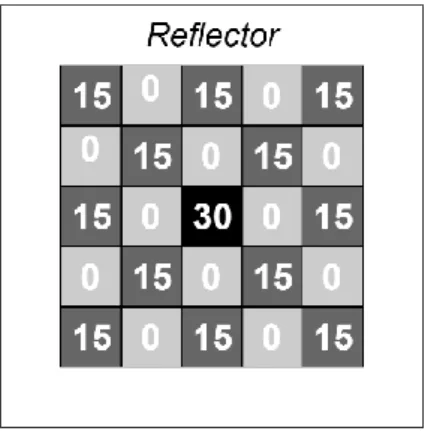
It is here reported the first step toward the objective of this work: the implementation of a steady-state calculation scheme capable of calculating a set of local parameters of a mini-core (including power distribution). The considered application is composed of 5x5 PWR assemblies surrounded by a reflector layer, top and bottom reflectors being included as well. The assembly’s dimensions are representative of a PWR. Two different isotopic compositions are considered for the radial reflector in order to evaluate the impact of the leakage on calculation scheme adopted: 95% of stainless steel, 5% (heavy reflector) water and 50% stainless steel, 50% water (standard reflector). The fuel assemblies are loaded with 4% enriched uranium, but the burnup map follows a chessboard-like configuration with values 0 or 15 MWd/kg (the corners are at 15 MWd/kg, see Fig. 1). The central assembly is at 30 MWd/kg. The choice
of the problem’s size results from the trade-off between representativeness and computation time, con-sidering that a systematic study will be carried out. Moreover, the small dimension of the core entails a power distribution more peaked than in standard PWR. At constant average linear power, a higher power form factor corresponds to a higher maximum linear power and a stronger multiphysics coupling, in the sense that variables are more linked to each other.
Figure 1: Burnup map at beginning of cycle. Values for the burnup of the fuel assembly in MWd/kg.
Since several years, the fine multiphysics modelling is a growing priority for many nuclear research teams. Some examples of the state of the art are available in [1,2]. In this context, CEA develops the multiphysics tool CORPUS [3] based on the SALOME platform [4]. The main CORPUS ambition is to develop and maintain a set of best‐estimate calculation schemes for different operating/accidental situ-ations in the framework of complete scenarios analysis. CORPUS gathers several independent codes and provides tools to help data exchanges among them. The neutronics code used for the calculation scheme is APOLLO3® [5], the deterministic multi-purpose code, able to perform both lattice and core calculations. It also includes a 1D, four equations thermal-hydraulics model, which is also capable of solving for the heat conduction in the fuel [6]. With respect to the thermal-hydraulics, the dedicated tool in CORPUS is FLICA4 [7], which offers a 3D, four equations model.
This work starts with a comparison among several neutronics models, at constant fuel temperature, moderator density and boron concentration. It follows the analysis of the impact of the two reflector compositions on the power distribution. Then, the obtained coupling scheme is described and its impact on reactivity and power distribution is assessed. The neutronics solvers are compared again, being coupled to a given thermal-hydraulics model in order to find the best-estimate scheme in terms of quality of local power prediction. Finally, the sensitivity of the coupling scheme results to the reflectors compo-sition is assessed with comparisons to the reference multiphysics scheme.
Comparison of various neutronics models using fixed thermodynamic parameters
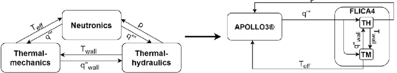
By fixed thermodynamic parameters, it is meant that the core conditions are known a priori, hence they might not be coherent with the actual power distribution. Instead of having iterations among solvers exchanging field of variables until convergence, fixed parameters are imposed and only neutronics is considered, as it is represented in Fig. 2.Figure 2: Schematization of a generic reactor physics coupling scheme (left), in contrast to the neutronics at constant parameters (right).
ensure the scalability to bigger domains and the possibility to implement advanced multiphysics iteration schemes, the widely used two steps approach is preferred here. The first step, lattice calculations, deals with a very accurate resolution of a subdomain of the problem (the 2D section of a fuel assembly with simplified boundary conditions) under a set of possible core conditions. The results are synthetized in homogenized and collapsed cross‐sections stored in a multi‐parametrized library. In this way, the prob-lem dimension is significantly reduced. During the second step, i.e. core calculations, these equivalent cross-sections are used to solve the entire problem (combination of the subdomains) on the 3D config-uration. The equivalent cross-sections are produced so that they preserve the reaction rates between the high and the low dimension problems as calculated by the lattice solver. With the super‐homogeni-zation equivalence procedure (SPH) [9], it is possible to store cross-sections reproducing the reference results when used by a specific core solver. Since the neutron energy spectrum in the reflector strongly depends on the surrounding assemblies, for its cross-sections a different approach is used, the 1D traverses technique [10]. Equivalent reflector cross-sections for a specific solver are obtained preserving the reference albedos at the core-reflector interface.
For the following analysis, cross-section libraries were produced by homogenizing the fuel assembly at the pin cell level and collapsing the number of groups to 2, 8, 20 and 30. For the lattice calculations, the method of characteristics (MOC) [11] with 281 energy groups is used in fundamental mode (critical buckling research with the B1 Homogeneous leakage model). These cross-sections are used by several neutronics models from diffusion to SPN and SN. The MINOS solver [12] is used for the first two and the SN is part of the MINARET solver [13]. For every set of cross-sections, the SPH equivalence calcu-lation is performed. The neutronics models are 2 groups diffusion (Diff.-2g), 8 groups Simplified Spher-ical Harmonics of order 3 (SP3-8g), 20 and 30 groups Discrete Ordinates of order 8 (20g and S8-30g). In addition to these, two groups cross-sections homogenized over the quarter of assembly have been produced for the diffusion solver. The S8 is used with the Discontinuous Galerkin method of order two both radially and axially, while for the SP3 and for the diffusion it is adopted the mixed dual finite element method with Raviart-Thomas basis functions of order two, both radially and axially. The calcu-lation radial mesh is equal to the one used for the homogenization. The calcucalcu-lation axial mesh is con-stant in the core and it is equal to 0.14224 m, in the top reflector it is 0.13 m and in the bottom one it is 0.09 m. The cross-sections are produced for a set of fuel effective temperatures, moderator densities, boron concentrations and burnups. The reflector is modelled as homogeneous, hence only an energy condensation of the cross-sections is done. Only the 2 groups cross-sections are produced with refer-ence albedos equivalrefer-ence technique, because this method is shown not to perform well for eight or more energy groups, for the others cross-sections no equivalence is applied. For simplicity and due to their weaker dependence, reflector cross-sections are produced only for nominal conditions.
For the following comparison, the fuel effective temperature, the moderator density and the boron con-centration are constant in the core; their values respectively are 655.8 °C, 0.701012 g/cm3 and 600 ppm.
The burnup map is the one described in the introduction (see Fig. 1). The boron concentration could also be considered as a multiphysics parameter, in the sense that the thermal-hydraulics solver might be used also to predict boron transport in the core. In this work, this effect is not taken into account. The compared variables are the reactivity, the 3D power distribution (fuel pin level) and the computation time. The S8-30g is used as reference for the other calculations. The results obtained for the heavy reflector are summarised in Table 1.
S8-30g S8-20g SP3-8g Diff.-2g Diff.-2g (quart) keff [-] 1.19746 1.19668 1.19670 1.19445 1.19415 Δρ [pcm] - -54 -53 -210 -231 [max(abs(ΔP/P))]core [%] - 0.93 2.76 8.17 (3.54) (4.19) [RMS(ΔP/P))]core [%] - 0.16 0.63 1.26 (1.07) (1.18) Fxy [-] 1.98359 1.98571 1.98380 1.96356 (1.61758) (1.62164) q’MAX [W/cm] 431.06 431.53 432.34 427.72 (391.28) (390.53) ti/tref [%] 100 63 3.7 0.1 0.001
Table 1: Performance assessment of neutronics solvers: multiplication factor, reactivity difference, maxi-mum absolute value and root mean square (RMS) of the relative errors on the power, radial power peak-ing factor, computpeak-ing times ratio. The values in parentheses result from a comparison on the quarter of
The SP3-8g predicts the integrated power at the pin cell scale within a root mean square (RMS) of the relative error that is rather satisfying, especially taking into account the much shorter computing time. The errors of the Diff.-2g on cell are evaluated on both the pin cell discretization and the quarter of assembly one. For the coarser mesh comparison, an interpolation is done for both the diffusion and the reference results. The discrepancies on the finer mesh are considered too high. Attention should be given to the fact that Diff.-2g with quarter of assembly discretization is compared to the reference only on the coarser mesh, as it is possible to notice on Fig. 3. Even if the diffusion approximation is based on hypotheses that are more valid for coarser meshes, the diffusion on cell produces better results than the one on quarter of assembly. This might be the consequence of the adjustment of cross sections with the SPH equivalence technique. Similar results are obtained for the standard reflector; in that case, the discrepancies are of the same order of magnitude, but slightly higher.
The plots of the power distribution comparison with SP3-8g and 2 groups diffusion on the quarter of assembly are available in Fig. 3. These methods represent the potential best-estimate and the standard approaches. In every comparison, the highest errors are close to the top and bottom reflector. This was rather predictable because no equivalence process has been performed for the reflector cross-sections, except for both 2 groups diffusion cross-sections. Furthermore, the neutron flux gradient is the highest close to the reflector, hence a refinement of the calculation axial mesh might be tested. In both compar-isons, in terms of solver precision, the SP3-8g is very close to the reference. The results are excellent in the central part of the core and in terms of maximum power prediction. However, since the purpose of this scheme is more general, a better reflector modelling has to be used to improve the results also in its proximity. The overall performance of the SP3-8g makes of it a good candidate for the best-esti-mate model.
Figure 3: Relative difference of the power distributions on the reactor core (reflector excluded). On the left SP3-8g vs S8-30g, on the right 2 groups diffusion (with quarter of assembly discretization) vs S8-30g.
Neutronics calculation sensitivity on the reflector composition
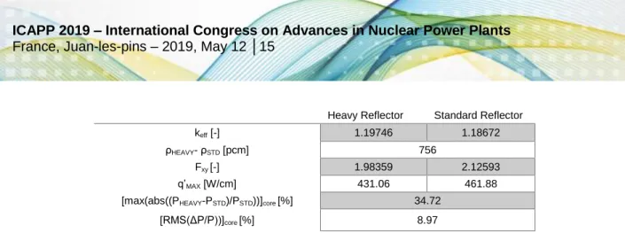
In this section, the S8-30g is used to assess the modelling sensitivity of the two considered radial re-flectors. The comparison in terms of reactivity and power distribution parameters are shown in Table 2, for the core parameters specified in the previous section. The difference in multiplication factor is signif-icant, at least for the current configuration.
Heavy Reflector Standard Reflector keff [-] 1.19746 1.18672
ρHEAVY- ρSTD [pcm] 756
Fxy [-] 1.98359 2.12593
q’MAX [W/cm] 431.06 461.88
[max(abs((PHEAVY-PSTD)/PSTD))]core [%] 34.72
[RMS(ΔP/P))]core [%] 8.97
Table 2: Neutronics parameters showing the sensitivity to the reflector composition: multiplication factor, reactivity difference, radial power peaking factor and distribution parameters of the relative power
dis-crepancy.
The discrepancies relative to the power distributions are shown in the radial section of the hot spot plane of the core available in Fig. 4. The elevations of the hot-spot for the two reactor configurations coincide. The radial power profile is considerably flattened in the case of the heavy reflector. The heavy reflector allows to shift the power distribution from the centre to the corners, reducing the maximum power from 462 to 431 W/cm. The only exception is the outermost layer of pin cells at the interface for which the power is higher with the standard reflector (neutrons thermalisation higher due to the different water percentages).
Figure 4: Relative difference of the power distributions in the core (reflector excluded), between the two reflector compositions. Northeast quarter of the radial section of the hot-spot plane of the core.
Description of the current coupling scheme
This coupling scheme architecture is developed with the objective of enabling physical modelling (neu-tronics, thermal-hydraulics and thermal-mechanics) at the appropriate scale. More in details, this scheme focuses on an efficient local power distribution calculation while the coolant properties (densities and temperature) might be estimated at various scale, from sub-channel to coarser scales. As far as the thermal calculation is concerned, local fuel pin temperature is needed to evaluate the heat flux on the cladding. This is a crucial parameter for the safety analysis, because it affects the possibility of having a boiling crisis. Empirical correlations provide a critical heat flux beyond which Departure from Nucleate Boiling (DNB) may occur.
From the numerical point of view, the coupled problem is modelled as a system of non-linear equations. The thermal-hydraulic and the thermal-mechanic equations are not linear. In the coupling scheme, also the neutronics becomes not linear. Because, the cross-sections depend on the fuel temperature and moderator density, which are affected by the heat source, hence by the neutron flux. The approach used in this work is fixed-point iterations with under-relaxation, a rather standard solution. It consists in suc-cessively solving the equations using the most updated variables. The computational cost is sufficiently low for this type of study and the scheme has proven to be stable, therefore the improvement of the numerical scheme is not addressed in the present work.
In Fig. 5, it is schematized how variables are exchanged among the solvers in the considered coupling scheme. FLICA4 is solving both the mechanics (reduced to heat conduction) and the
thermal-hydraulics. In steady state conditions, if the thermal-mechanics model is 1D, a further simplification might be applied. The heat is not accumulating anywhere, so the wall heat flux is automatically defined by the heat source and the geometry. Therefore, the heat conduction can be solved as a post-processing of the thermal-hydraulics.
Figure 5: Map of data exchange in the coupling scheme. As a first step, FLICA4 is solving both the ther-mal-hydraulics and the thermal-mechanics.
All the results presented in this section are produced using this coupling scheme. With respect to the thermal-hydraulics, the 3D porous model – four equations of FLICA4 is used. Each fuel assembly is represented using four meshes. The top and the bottom reflectors are modelled. The radial one is not, because its influence on the adjacent assemblies is low and the radial reflector cross-sections are not parametrized in moderator density. A representation of the three different scales adopted for neutronic, thermal-hydraulic and heat conduction calculations is given in Fig. 6. Eight mixing grids are also consid-ered. Closed surfaces are used only at core boundaries, no heat nor mass transfer out of the core are considered. Inlet enthalpy and water mass flux are representative of a standard PWR. One equivalent fuel rod is modelled per each thermal-hydraulic region. Heat conduction is solved with a 1D model, considering the gap heat transfer coefficient to be constant and the fuel conductivity only depending on the temperature. The adopted scale for neutronics allows to calculate the power distribution at the pin cell level with the thermodynamic quantities averaged on the quarter of assembly.
Figure 6: Refinement level of each physics. For the thermal-mechanics one average fuel pin per quarter of assembly is represented.
The data exchanges and the iteration scheme are managed in the CORPUSSALOME environment. The
latter allows prompting the codes, and to get and set fields and variables. SALOME offers a standardized way of storing and recovering meshes and fields, the MED format. Such a tool offers the possibility to persistently store data on a format based on Hierarchical Data Format (HDF) [14], but also to exchange data among solvers directly in memory. Many interpolation tools are available in SALOME. During every iteration, APOLLO3® and FLICA4 need to exchange fields of variables. Apart from the diffusion model, which is on the quarter of assembly discretization, the neutronics is at the pin cell scale, hence interpo-lation is needed every time a field is exchanged. Effective fuel temperature and density are exchanged as an intensive field, their volume integral over the domain is conserved. The integral power is trans-ferred as an extensive field, the summation over the regions is preserved.
In following sections, this scheme is used to assess the impact of adding the thermal-hydraulic and thermal-mechanic feedback, to find its best-estimate version and evaluating the impact of the reflector composition.
Impact of multiphysics modelling
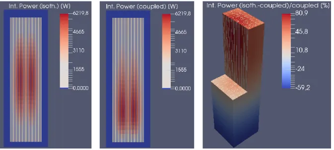
In this section, the results from the coupling scheme are compared to the ones obtained in the first part using constant parameters. In Fig. 7, it is reported the comparison of the power distributions obtained with the two approaches. In both cases, the neutronics model is the S8-30g. As expected, the coupled scheme finds a power shape whose maximum is shifted from the centre to the bottom of the core due to the higher moderator density. The axial profile is radically changed, especially in the core periphery, where the moderator density and the fuel temperature differ the most from their average values. In terms of radial variation, the coupled solution is quite flatter, as it is also possible to see comparing the radial peaking factors (Pxy) in Tables 4 and 1. The total power peaking factor increases from 2.45 to 2.78, causing the maximum linear power increase from 392 to 445 W/cm (the average linear power is 160 W/cm). As it is possible to see in Table 3, in terms of reactivity, all the models agree on a variation around 470 pcm. The temperature and density distribution are compared to the constant values imposed in the previous sections, 655.8 °C, 0.701012 g/cm3.The results show that the different coupling schemes
agree quite well on the estimation of the impact of multiphysics calculation.
Figure 7: Axial cuts of the power distributions, on the left at constant parameters, in the centre as con-verged in the coupling scheme (reflector included). On the right, the 3D relative difference between the
two cases (reflector excluded).
S8-30g S8-20g SP3-8g Diff.-2g Diff.-2g (quart) Δρ [pcm] -472 -472 -470 -465 -467 [Max(abs(ΔTfuel))]core [K] 604 605 606 598 602
[RMS(ΔTfuel) ]core [K] 219 219 219 219 220
[Max(abs(Δdensitymod))]core [g/cm3] 0.0772 0.0773 0.0773 0.0766 0.0769
[RMS(Δdensitymod)]core [g/cm3] 0.0308 0.0308 0.0309 0.0308 0.0309
Table 3: Comparison of global parameters between the constant parameters and the coupled simulations: reactivity difference, distribution parameters of fuel temperature and moderator density discrepancies.
Neutronics solver comparison in the coupling scheme
In this section, analogously to the second one, the neutronics solvers performances are studied, in this case, within the coupling scheme with quarter of assembly thermal-hydraulics model and one average
pin per quarter of assembly for the heat conduction. The stand-alone thermal-hydraulics and heat con-duction calculations need approximately the same time as the one required by the 2 groups diffusion simulation at the fuel cell scale. Such a proportion is not exactly kept in the coupled calculation, because the two models may converge at different paces.
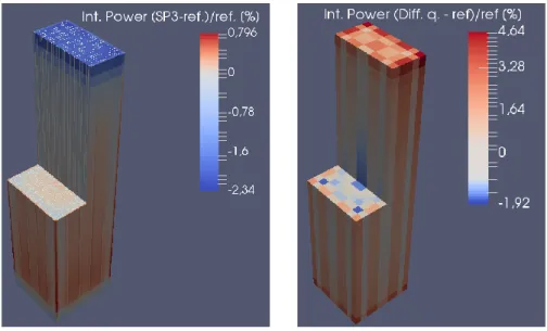
Table 4 contains the performance analysis of the neutronics solver in the multiphysics calculations. The SP3-8g confirms its excellent performance also in the coupling scheme, the maximum absolute discrep-ancy with the reference power distribution is equal to 2.34%. As it is possible to see in Fig. 8, the highest errors are still in the proximity of the reflectors were the power is the lowest. In terms of maximum linear power, the SP3-8g is in good agreement with the reference. The shape and the global magnitude of the error on power distribution are comparable to the ones obtained at constant parameters. The overall performance of the SP3-8g makes of it the best-estimate model for this study context.
S8-30g S8-20g SP3-8g Diff.-2g Diff.-2-g (quart) keff [-] 1.19073 1.18996 1.19001 1.18785 1.18753 Δρ [pcm] - -54 -51 -204 -226 [max(abs(ΔP/P))]core [%] - 1.07 2.34 8.38 (3.80) (4.64) [RMS(ΔP/P))]core [%] - 0.26 0.45 1.31 (1.13) (1.29) Fxy [-] 1.87782 1.87970 1.87690 1.86271 (1.54051) (1.54383) q’MAX [W/cm] 445.39 445.80 445.70 442.13 (405.06) (404.83) ti/tref [%] 100 40 1.65 1.32 0.06
Table 4: Performance assessment of neutronics solvers in the coupling scheme: multiplication factor, reactivity difference, maximum absolute value and root mean square of the relative errors on the power,
radial power peaking factor, computing times ratio. Values in parentheses result from a comparison on the quarter of assembly. S8 calculations are performed with twenty processors, the others with only one.
Figure 8: Relative difference between the power distributions on the reactor core (reflector excluded), as predicted by the coupled calculations. On the left SP3-8g vs S8-30g, on the right 2 groups diffusion with
quarter of assembly discretization vs S8-30g.
Calculation scheme sensitivity on reflector composition
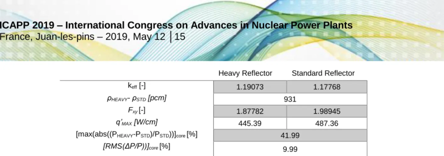
The impact of the reflector composition is here assessed with the reference coupling scheme (the one with S8-30g as neutronics model). In Table 5, the results in terms of reactivity and power distribution are shown. The discrepancy on the power distribution is illustrated in Fig. 9, for which the radial section of the core at the hot point is reported. In this case, the maximum discrepancies are not in the plane of the hot point; they are in the top and the bottom regions of the core. However, a significant reduction of the power peak is seen in the hot spot radial section.
Heavy Reflector Standard Reflector keff [-] 1.19073 1.17768
ρHEAVY- ρSTD [pcm] 931
Fxy [-] 1.87782 1.98945
q’MAX [W/cm] 445.39 487.36
[max(abs((PHEAVY-PSTD)/PSTD))]core [%] 41.99
[RMS(ΔP/P))]core [%] 9.99
Table 5: Neutronics parameters showing the impact of the reflector composition.
Figure 9: Relative difference of the power distributions in the core (reflector excluded), between the two reflector compositions. Northeast quart of the radial section of the hot-spot plane of the core.
The hot-spot plane is not exactly at the same elevation for the two core configurations, the one with the standard reflector is around 10 cm lower than the one with the heavy reflector. The global results on the impact of reflector composition are similar to the ones obtained with the isothermal model. The reactivity difference has increased up to 931 pcm. Both the radial power peaking factors have decreased in the coupled calculations. Moreover, the heavy reflector does offer a flatter radial profile and a more reactive core. In terms of maximum linear power, the higher form factor entails 487 W/cm of peak power, so 10% higher than the one corresponding to the heavy reflector.
Conclusion
The objective of this work is to develop a best-estimate multiphysics scheme to predict the local power in steady state conditions. The domain of application is a 3D 5x5 PWR mini-core, with a layer of radial reflector and top and bottom reflectors. Two isotopic compositions are considered for the radial reflector, the water-stainless steel mixture is either 50% and 50% (standard reflector) or 5% and 95% (heavy reflector).
In a preliminary comparison of neutronics solvers at isothermal conditions, the SP3 with 8 energy groups has emerged as the best compromise between precision and calculation time. The standard deviation of the relative error on the power profile, in comparison to the S8 with 30 energy groups, is of 0.63% over the fuel pin cell. The computing time is only 3.7% of the reference one. The radial reflector isotopic composition has proven to significantly change the radial power shape, yielding a flatter power distribu-tion: the standard reflector power radial peaking factor is 2.12593, as compared to the heavy one of 1.98359. Moreover, the heavy reflector core is 756 pcm more reactive. However, the discrepancies identified using SP3-8g modelling are not amplified when changing the type of reflector.
In the second part, a multiphysics coupling scheme is built; several neutronics solvers, modelling the reactor at the fuel pin cell scale, are coupled with a thermal-hydraulics 3D four-equation model with a quarter of assembly discretization. The 1D heat conduction is solved for one average pin per quarter of assembly. The local power is predicted using thermodynamic variables averaged on the quarter of fuel assembly. The comparison between the constant parameters model and the coupled calculation point
out the importance of coupled calculations. The different schemes show good agreement on the as-sessment of the impact of the other physics on neutronics.
In the coupled scheme, the comparison among the neutronics solvers underlines again the excellent performance of the SP3 with 8 energy groups. Using again the S8-30g model as reference, the root mean square of the relative error of the power distribution of the SP3-8g solver is found to be 0.45% over the fuel pin cell and the relative error on the maximum linear power is 0.07%. The computing time is only the 1.65% of the reference. The multiphysics assessment of the reflector composition impact leads to results coherent with the neutronics modelling. The radial power peaking factor for the heavy and the standard reflectors are respectively 1.87782 and 1.98945. The reactivity difference has in-creased up to 931 pcm. The maximum linear power with standard reflector is 10% higher, 487 W/cm. After examining the performance of the SP3-8 g in the coupling scheme, it is considered to be best-estimate model, at least for this context of study.
In order to achieve higher performance and to be able to model bigger domains it is planned to test more advanced numerical algorithm. In addition, it is expected to explore coupling schemes with ther-mal-hydraulics and thermal-mechanics on finer scales.
Acknowledgment
Thanks to Roland Lenain and Cyril Patricot for their valuable help.
References
1) Turner, John A., et al., “The virtual environment for reactor applications (VERA): design and architecture,”
Jour-nal of ComputatioJour-nal Physics, 326, pp. 544-568 (2016).
2) Jung, Yeon Sang, et al., “Practical numerical reactor employing direct whole core neutron transport and
sub-channel thermal/hydraulic solvers,” Annals of Nuclear Energy, 62, pp. 357-374 (2013).
3) Le Pallec, J.C. et al., “Neutronics/Fuel Thermomecanics coupling in the Framework of a REA (Rod Ejection Accident) Transient Scenario Calculation.” In Proc. Int. Conf. Physics of Reactors (PHYSOR2016).
4) “SALOME platform,” http://www.salome-platform.org .
5) Schneider, D. et al., “APOLLO3®: CEA/DEN deterministic multi-purpose code for reactor physics analysis.”
In Proc. Int. Conf. Physics of Reactors (PHYSOR2016).
6) Patricot, C., “THEDI: a multi-1D two-phase flow solver for neutronic codes.” In Proc. ICAPP2019.
7) Toumi, I. et al., “FLICA4: a three dimensional two-phase flow computer code with advanced numerical methods for nuclear applications,” Nuclear Engineering and Design, 200, pp.139-155 (2000).
8) Santandrea, S., Graziano, L. and Sciannandrone, D., "Accelerated polynomial axial expansions for full 3D neutron transport MOC in the APOLLO3® code system as applied to the ASTRID fast breeder reactor," Annals
of Nuclear Energy, 113, pp. 194-236, (2018).
9) Kavenoky, A., “The SPH homogenization method,” In Proc. Specialists’ Mtg. Homogenization Methods in
Re-actor Physics, Lugano, Switzerland, Nov. 13e15, 1978.
10) Sandrin, C., Sanchez, R., & Dolci, F., “An analysis of reflector homogenization techniques for full core diffusion calculations,” Nuclear Science and Engineering, 168(1), pp. 59-72, (2011).
11) Santandrea, S., et al.,“A neutron transport characteristics method for 3D axially extruded geometries coupled
with a fine group self-shielding environment,”Nuclear Science and Engineering,186(3), pp. 239-276 (2017).
12) A.-M. Baudron and J.-J. Lautard. “MINOS : A simplified Pn solver for core calculation.”Nuclear Science and
Engineering, 155(2), pp. 250–263 (2007).
13) Moller, J. Y., and J. J. Lautard. "Minaret, a deterministic neutron transport solver for nuclear core calculations." (2011).