HAL Id: tel-02482433
https://tel.archives-ouvertes.fr/tel-02482433
Submitted on 18 Feb 2020HAL is a multi-disciplinary open access archive for the deposit and dissemination of sci-entific research documents, whether they are pub-lished or not. The documents may come from teaching and research institutions in France or abroad, or from public or private research centers.
L’archive ouverte pluridisciplinaire HAL, est destinée au dépôt et à la diffusion de documents scientifiques de niveau recherche, publiés ou non, émanant des établissements d’enseignement et de recherche français ou étrangers, des laboratoires publics ou privés.
Conductive Atomic Force Micros-copy (C-AFM) in
Ultra-High Vacuum Environment
Amit Kumar Singh
To cite this version:
Amit Kumar Singh. Resistive Non-Volatile Memories Characteri-zation by Conductive Atomic Force Micros-copy (C-AFM) in Ultra-High Vacuum Environment. Micro and nanotechnolo-gies/Microelectronics. Université Grenoble Alpes, 2019. English. �NNT : 2019GREAT033�. �tel-02482433�
THÈSE
Pour obtenir le grade de
DOCTEUR DE LA
COMMUNAUTÉ UNIVERSITÉ GRENOBLE ALPES
Spécialité : NANO ELECTRONIQUE ET NANO TECHNOLOGIES Arrêté ministériel : 25 mai 2016Présentée par
Amit Kumar SINGH
Thèse dirigée par Martin KOGELSCHATZ, MCF, Université Grenoble Alpes
et codirigée par Serge BLONKOWSKI, STMicroelectronics
préparée au sein du Laboratoire Laboratoire des Technologies de la Microélectronique
dans l'École Doctorale Electronique, Electrotechnique, Automatique, Traitement du Signal (EEATS)
Caractérisation des Mémoires Non-Volatiles
Résistives par Microscopie à Force
Atomi-que en mode Conduction (C-AFM) sous
Ultravide
Resistive Non-Volatile Memories
Characteri-zation by Conductive Atomic Force
Micros-copy (C-AFM) in Ultra-High Vacuum
Environment
Thèse soutenue publiquement le 24 juin 2019, devant le jury composé de :
Monsieur LAMBERT ALFF
PROFESSEUR, UNIV. TECH. DE DARMSTADT - ALLEMAGNE, Rapporteur
Monsieur BRICE GAUTIER
PROFESSEUR, INSA LYON, Rapporteur Monsieur ALAIN SYLVESTRE
PROFESSEUR, UNIVERSITE GRENOBLE ALPES, Président Madame CLAUDIA WIEMER
CHARGE DE RECHERCHE, CNR IMM AGRATE UNIT, Examinateur Monsieur MARTIN KOGELSCHATZ
MAITRE DE CONFERENCES, UNIVERSITE GRENOBLE ALPES, Directeur de thèse
Monsieur SERGE BLONKOWSKI
INGENIEUR, ST MICROELECTRONICS CROLLES, Co-directeur de thèse
U
NIVERSITÉ
G
RENOBLE
A
LPES
D
OCTORALT
HESISResistive non-volatile memories
characterization by conductive atomic
force microscopy (C-AFM) in ultra-high
vacuum environment
Author:
Amit Kumar SINGH
Supervisor: Serge BLONKOWSKI Guillaume AUDOIT
iii
Abstract
Title: Resistive non-volatile memories characterization by conductive
atomic force microscopy (C-AFM) in ultra-high vacuum environment.
Memories are the fundamental for any electronic system we interact with in our daily life and are getting more and more important day by day in our present era. Non-volatile memory (NVM) technologies play a fundamental role in the micro-electronics industry. The growing functionalities and performance of the electronic products such as digital cameras, smart phone, personal computer, solid state hard disk and many more, need continues improvement of its features.
Floating gate-based Flash technology is the main NVM technology used exten-sively in market these days. Nevertheless, Flash technology presents many prob-lems making further scaling impossible. In this context, there are many other mem-ory technologies emerging and interest in new concepts and materials to go beyond the Flash technology is growing. Innovative approaches other than displacing and trapping electrons like in Flash memories have been investigated.
Resistive non-volatile memories based on two terminal devices, in which an ac-tive material is sandwiched between two electrodes have been investigated. The main idea of using this kind of structure and material is to use a specific physical mechanism allowing to switch it between two different resistive states for informa-tion storage.
For example, in oxide based random-access memory (OxRAM), a conductive fil-ament is grown inside the oxide layer, linking the two electrodes. By creation and disruption of this filament, two different resistance states can be generated. An-other example is the phase change random-access memory (PCRAM), in which a chalcogenide material with the ability to change its phase between a high resistive amorphous and a low resistive crystalline state is used. These two emerging mem-ory technologies (OxRAM & PCRAM) are the most studied ones nowadays and can potentially replace the current Flash technology.
Over the last few years OxRAM has been widely investigated due to many ad-vantages like good scalability, long data retention time, fast read & write speed and low power consumption. The main benefit is that it is compatible with Back-end of line fabrication. In MIM structures for OxRAM, forming and disruption of the nanometer sized conductive filament is commonly accepted as the physical phe-nomenon for the switching, but still a debate is going on to understand the nature and characteristics of the conductive filament. Also, many studies have been done to evaluate the scaling capability of OxRAM and PCRAM.
Hence, in this thesis work we studied mechanisms related to the conductive fil-ament based resistive switching at nanoscale. To do the electrical characterization, a new technique using conductive atomic force microscopy (C-AFM) in ultra-high
vacuum is proposed. The impact of different AFM tip materials (which is used as top electrode), different bottom electrode materials and the compliance current ef-fect in two different regimes (in nA and in µA) are investigated. It is found that in the case of H f O2based OxRAM, the filament is formed by Ti diffusion from the
bot-tom electrode through the oxide layer. The switching is due to the disruption of the filament in the vicinity of the tip explaining the effect of the tip nature on the High resistance current. The results are in good agreement with device characteristics and could be reproduced by modeling. Also, phase transition in phase change materials for PCRAM is investigated for Ge2Sb2Te5(GST-225) and Ge rich GST. It was found
that the phase transition from amorphous to crystalline is possible at nanoscale. Fi-nally, the threshold for GST-225 is observed at values nearer to those observed on devices than former observations with standard C-AFM.
Keywords: Non-Volatile Memories, OxRAM, PCRAM, Conductive atomic force mi-croscopy (C-AFM), Nanoelectronics, Microelectronics, Ultra-high vacuum, Electrical char-acterization, Filament, Simulation.
v
Resumé
Titre: Caractérisation des mémoires non volatiles résistives par
micro-scopie à force atomique en mode conduction (C-AFM) sous ultravide.
Les mémoires sont à la base de tout système électronique avec lequel nous inter-agissons dans notre vie quotidienne et deviennent de plus en plus important jour après jour à notre époque. Les technologies de mémoire non volatile (NVM) jouent un rôle fondamental dans l’industrie de la microélectronique. Les fonctionnalités et les performances croissantes des produits électroniques tels que les appareils photo numériques, les téléphones cellulaires, les ordinateurs personnels, les disques durs, etc., nécessitent une amélioration continue de ses fonctionnalités.
La technologie Flash à grille flottante est la principale technologie NVM utilisée sur le marché actuellement. Néanmoins, la technologie Flash pose de nombreux problèmes rendant tout redimensionnement impossible. Dans ce contexte, de nom-breuses autres technologies de mémoire sont en train d’émerger et l’intérêt pour les nouveaux concepts et matériaux allant au-delà de la technologie Flash ne cesse de croître. Des approches innovantes autres que le déplacement et le piégeage des élec-trons comme dans les mémoires Flash ont été étudiées.
Des mémoires résistives non volatiles basées sur deux types de dispositifs, dans lesquelles un matériau actif est pris en sandwich entre deux électrodes, ont été étudiées. L’idée principale d’utiliser ce type de structure et de matériau est d’utiliser un mé-canisme physique spécifique permettant de le basculer entre deux états résistifs dif-férents pour le stockage d’informations.
Par exemple, dans la mémoire à base d’oxydes (OxRAM), un filament conduc-teur est développé à l’intérieur de la couche d’oxyde, reliant les deux électrodes. En créant et en interrompant ce filament, deux états de résistance différents peuvent être générés. Un autre exemple est la mémoire à changement de phase (PCRAM), dans laquelle un matériau à base de chalcogénure capable de changer de phase entre un état amorphe à haute résistance et un état cristallin à faible résistance est utilisé. Ces deux technologies de mémoire émergentes (OxRAM & PCRAM) sont les plus étudiées et peuvent potentiellement remplacer la technologie Flash actuelle.
Les mémoires OxRAM ont été largement étudiées au cours des dernières années en raison de leurs nombreux avantages, tels qu’une bonne évolutivité en matière de réduction de taille, une longue rétention, une vitesse de lecture et d’écriture rapide et une faible consommation d’énergie. Le principal avantage est leur compatibilité avec la fabrication en back end. Dans les structures MIM pour OxRAM, la forma-tion et la rupture d’un filament conducteur de taille nanométrique sont communé-ment acceptées comme étant le phénomène physique de la commutation, mais un débat est toujours en cours pour comprendre la nature et les caractéristiques du fil-ament conducteur. De plus, de nombreuses études ont été réalisées pour évaluer le potentiel de réduction des dimensions des mémoires OxRAM et PCRAM. Par
conséquent, dans cette thèse, nous étudions les mécanismes liés à la commutation résistive à base de filaments conducteurs à l’échelle nanométrique. Pour effectuer la caractérisation électrique, une nouvelle technique utilisant la microscopie à force atomique en mode conduction (C-AFM) sous ultravide est proposée. L’influence du matériau de la pointe AFM (utilisés comme électrode supérieure), du matériau de l’électrode inférieure et l’effet du courant limite dans deux régimes différents (en nA et en µA) sont étudiés. Il ressort de notre travail que dans les mémoires OxRAM à base de H f O2, le filament est créé par diffusion de Ti de l’électrode inférieure à
travers l’oxyde. D’après le travail présenté dans cette thèse, la commutation résis-tive est due à la rupture du filament au voisinage de la pointe expliquant l’effet dû à la nature de la pointe sur le courant à haute résistance. Les résultats sont en bon accord avec ceux obtenus sur des dispositifs et ont pu être reproduits par un modèle. En outre, la transition de phase dans les matériaux pour PCRAM est étudiée pour le GST riche en Ge et le GST-225. Il a été constaté que la transition de phase dans les matériaux à changement de phase est possible à l’échelle nanométrique. Enfin, le champ électrique de seuil observé dans le cas du GST-225 est bien plus proche des valeurs mesurées sur dispositifs que celles obtenues avec un CAFM standard.
Mots-clés: Mémoires non volatiles, OxRAM, PCRAM, Microscopie à force atomique conductrice (C-AFM), nanoélectronique, microélectronique, ultravide, caractérisation élec-trique, filament, simulation.
vii
Acknowledgements
Firstly, I would like to express my sincere gratitude towards my supervisors Serge BLONKOWSKI, Martin KOGELSCHATZ and Guillaume AUDOIT for the continu-ous support of my Ph.D study and related research, for their patience, motivation, and immense knowledge. Their guidance helped me in all the time of research and writing of this thesis. I could not have imagined having a better advisor and mentor for my Ph.D study. I would also like to thank all my jury members.
A very special thanks to Olga CUETO for being a constant support always and helping me understand the COMSOL simulation part of this research project. I thank her for her patient guidance, useful critiques and answering my incessant queries. I would like to thank Constantin MATEI for performing SEM-EDX measurements with me. I would also like to thank Tristan DEWOLF for TEM analysis. I would like to thank Chiara SABBIONE and Gabriele NAVARRO for providing the samples.
My sincere thanks also goes to all the lab members, who provided me an op-portunity to join their lab as PhD student, and who gave access to the laboratory and research facilities. Without their precious support it would not be possible to conduct this research. I would like to thank my fellow doctoral students for their feedback, cooperation and of course friendship.
I would like to thank my friends for accepting nothing less than excellence from me. Last but not the least, I would like to thank my family: my parents and to my brothers for supporting me spiritually throughout writing this thesis and my life in general.
ix
Contents
Introduction 1
1 Memory Landscape and Emerging Technologies 5
1.1 Overview of memory technology . . . 6
1.1.1 Volatile Memories . . . 6
Static random-access memory . . . 6
Dynamic random-access memory . . . 6
1.1.2 Nonvolatile memories . . . 7
1.2 Emerging nonvolatile memory technologies . . . 8
1.2.1 Flash . . . 8 1.2.2 FeRAM . . . 10 1.2.3 MRAM . . . 11 1.2.4 CBRAM . . . 13 1.2.5 PCRAM . . . 14 1.2.6 OxRAM . . . 16
1.3 Oxide based random access memory . . . 16
1.3.1 Basic Operation of OxRAM . . . 16
1.3.2 Materials . . . 20
1.3.3 Electrode material effect on switching behavior . . . 22
1.3.4 Switching mechanisms . . . 23
Switching based on oxygen ion migration . . . 25
Switching based on Metal ions migration . . . 25
Switching based on thermochemical reaction . . . 26
1.3.5 Conduction Mechanism . . . 27
1.4 Phase change random access memory (PCRAM or PCM) . . . 27
1.4.1 The PCM Cell Structure and its switching mechanism . . . 28
1.4.2 Phase Change Materials . . . 29
1.5 Conductive atomic force microscopy for resistive memories . . . 31
1.5.1 For OxRAM . . . 31
1.5.2 For PCRAM . . . 35
1.6 Conclusion . . . 37
2 Experimental Techniques 39 2.1 Atomic Force Microscopy . . . 39
2.1.1 Introduction & Basic Principle . . . 39
2.1.2 AFM tips . . . 40
2.1.3 Surface Contact Area . . . 42
2.1.4 AFM in ultra-high vacuum . . . 43
2.1.5 Calibration of AFM Tips . . . 44
2.1.6 Sample Preparation . . . 48
2.2 Measurement with AFM . . . 49
2.2.1 Topography Characterization . . . 49
2.3 Scanning Electron Microscope . . . 51
2.3.1 Introduction and Basic Principle . . . 51
2.4 SEM EDX . . . 53
2.4.1 Introduction and Basic Principle . . . 53
2.5 Conclusion . . . 54
3 Impact of Compliance Current on Resistive Switching in OxRAM 55 3.1 Introduction . . . 55
3.2 Experimental Observations . . . 55
3.2.1 Switching Behavior based on polarity . . . 55
3.2.2 Low Compliance current effect (in the range of nA) . . . 58
3.2.3 High Compliance current effect (in the range of µA) . . . 59
3.2.4 Threshold compliance current for full filament formation . . . . 63
3.3 Discussion for Low Compliance (in nA range) . . . 65
3.3.1 Filament Growth Model . . . 65
3.3.2 Discussion & Model Comparison with experiments . . . 68
3.4 From low compliance to high compliance (in µA range) . . . 70
3.5 Conclusion . . . 72
4 High Compliance Effect on Switching in OXRAM 75 4.1 Introduction . . . 75
4.2 Experimental Observations . . . 76
4.2.1 Effect of AFM tips . . . 76
AFM Probe material effect . . . 76
AFM tip size effect . . . 77
4.2.2 SEM-EDX Study . . . 80
4.2.3 TEM Analysis of Hillocks on TiN/H f O2surface . . . 84
4.2.4 Effect of bottom electrode . . . 88
4.2.5 GonVariation with compliance . . . 88
4.2.6 Effect of Polarity . . . 90
4.2.7 C-AFM experiments comparison with 1T1R Device . . . 90
4.2.8 Effect of Series Resistance on switching behavior . . . 92
4.3 Discussion . . . 96
4.3.1 Model Description . . . 96
4.3.2 Model comparison with experiments . . . 100
4.4 Conclusion . . . 108
5 Switching in Phase Change Materials 109 5.1 Introduction . . . 109
5.1.1 GST samples and experimental methods . . . 110
5.2 Experimental Observations . . . 113
5.2.1 Ramp Speed effect . . . 113
5.2.2 Capping Layer effect . . . 113
5.2.3 Topographical study for different PCM samples . . . 115
5.2.4 GST 225 vs GSTθ . . . 118
5.3 Modeling . . . 120
5.3.1 Analytic models for amorphous layers . . . 120
Off-state conductance model . . . 121
On-state conductance model . . . 122
5.3.2 Finite Elements Method (FEM) Approach . . . 122
xi
5.5 Conclusion . . . 129
Conclusion & Perspective 133
xiii
List of Figures
1.1 Overview of different memory technologies[1]. 4F2represents the cell
dimension where F is the minimum feature size. . . 5
1.2 A typical cell structure of SRAM memory. . . 6
1.3 A typical cell structure of DRAM memory. . . 7
1.4 A die photograph of the Micron Technology MT4C1021 DRAM inte-grated circuit. . . 7
1.5 Comparison of different cell structures for different types of memory technology[4]. . . 8
1.6 (left) Basic structure of Flash memory cell (right) Example of corre-sponding IV characteristics; adopted from[12]. . . . 9
1.7 Comparison of NOR Flash array and NAND Flash array architectures[4]. 10 1.8 32-layer 3D NAND Flash produced by Intel[16]. . . 10
1.9 On left hand, the basic structure of a FeRAM cell is shown. On top right crystal structure of ferroelectric and on bottom right an electric polarization-electric field hysteresis curve are also shown[4]. . . 11
1.10 Simple structure of a magnetic tunnel junction is shown in the left side and variation in resistance with magnetic field is shown in the right side with two different magnetic states, the parallel one and the anti-parallel one[30]. . . 12
1.11 Schematic of 1-transistor, 1-MTJ cell. . . 12
1.12 Schematic illustration of the CBRAM switching mechanism[42]. . . 13
1.13 Typical I-V characteristic of Ag/Ag-Ge-Se/Pt electrochemical metal-lization cell. Adopted from reference[48]. . . 14
1.14 Schematic of a PCRAM cell[49]. . . 14
1.15 Historical timeline of RRAM development from 1962 to 2017. Adopted from[52]. . . 17
1.16 Dependence of cell dimension on the resistance in on and off state (right coordinate axis)[67]. . . 18
1.17 Different steps for RRAM operation showing forming of the conducitve filament, SET and RESET[68]. . . 18
1.18 (a) Basic structure of OxRAM or RRAM with metal-insulator-metal configuration, (b) Unipolar switching behaviour in an OxRAM device and (c) Bipolar switching behaviour in an OxRAM device[69]. . . 19
1.19 I-V characteristic for a bipolar OxRAM device showing forming, SET and RESET steps[70]. . . 19
1.20 I-V characteristic Pt/TaOx reported by Yang et al.[139]. . . 21
1.21 I-V characteristic TiOx based RRAM reported by Park et al.[76]. . . 21
1.23 Schematic description of the RS mechanism of the device. (a) Before and (b) after the Ti top electrode deposition. (c) CF grows from TiN to Ti electrodes under a positive forming voltage applied to it. (d) A neg-ative voltage is applied on it to rupture the CF. (e) CF formation and some oxygen ions release during set process. (f) CF ruptures during reset process[177]. . . 24 1.24 A schematic diagram for mechanism of resistive switching effects in
ECM cell: (a) Electrochemically active metal atoms oxidize to ions at the anode, and then the active metal ions migrate to the cathode and deoxidize therein; (b) Precipitations of active metal atoms at the elec-trochemically inert electrode leading to the formation of a highly con-ductive filament in the cell; (c) When the polarity of the applied volt-age is reversed, an electrochemical dissolution of the filament takes place, resetting the system into HRS[91]. . . 25 1.25 Schematic diagram for the mechanism of resistive switching in Pt/ZnO/Pt
devices. (a) The release of oxygen gas O2leads to the oxygen
vacan-cies in the bulk of ZnO. (b) The migration of the mobile oxygen va-cancies toward the cathode (oxygen ions O2 towards the anode) and the rearrangement of Zn-dominated ZnO1x. (c) The precipitation of
Zn atoms to form a conductive filament. (d) The rupture of the fila-ment. When the energy of Joule heating enhances the thermochemical reaction, the filament will rupture and change back to ZnO. Due to the migration of oxygen ions, the ReRAM resets back to the off state. Text and figure are adopted from reference[186]. . . 26 1.26 Schematic of the possible conduction mechanism in TiN/HfOx/Pt
stack: (1) Schottky emission; (2) Fowler-Nordheim (F-N) tunneling; (3) direct tunneling; (4) tunneling from cathode to traps; (5) emission from trap to conduction band, which is essentially the Poole-Frenkel emission; (6) F-N like tunneling from trap to conduction band; (7) trap to trap tunneling; and (8) tunneling from traps to anode. Adopted from reference[189]. . . 27 1.27 Programming for read, set and reset for PCM devices[193]. . . 28
1.28 (a) Schematic of a general PCM cell[199](b) I-V characteristic of a PCM cell showing the amorphous and crystalline phase[200]. . . 29 1.29 Tertiary Ge−Sb−Te phase diagram with some popular phase change
alloys highlighted. The red arrow indicates the trend of adding Ge to Ge2Sb1Te2alloys[201]. . . 30
1.30 Resistivity as a function of the temperature for GeTe phase change material[199]. . . 30 1.31 Schematic representation of phase transformation during the record
and erase process for Ge2Sb2Te5and GeTe[208]. . . 31
1.32 1-V characteristic of TiO2-x (black curve) and TiOx (blue curve) thin films obtained by C-AFM[230] . . . 32 1.33 The C-AFM tip is placed in contact with H f O2layer and a tip-surface
contact area of 3×3nm2is achieved by the precise control of the load force applied to the tip by Hou et al.[231]. . . 32 1.34 (a) Schematic diagram of the H f O2/ITO/Invar RRAM structure with
an AFM Pt/Ir tip as the top electrode. (b) Typical nanoscale I-V char-acteristics of the H f O2/ITO/Invar structure observed by Wu et al.[232]. 33
xv
1.35 C-AFM mediated surface conductivity modifications of the TiO2thin
film. (a) Topography (b) Current map. The surface is more insulating with 5V (upper region) and more conducting with +5V (lower region) surface, compared to surface in pristine state. One conducting spot is shown on the lower right corner. (c) Current mapping image in 3D of the same area[233]. . . 33 1.36 I-V characteristic measured by CAFM on a TiO2/Pt surface, at a
volt-age sweep by C-AFM observed by Du et al.[233]. . . 34 1.37 (a) RS I-V curves of a 50×50nm2 TiN/H f O2/H f /TiN device in the
1T1R cell with 250 µA compliance current (b) RS I-V curves of the blunt−tip/H f O2/H f /TiN tip-induced cell, the 1st (red trace) and
the 100th (blue trace), as presented by Hou et al.[143]. . . 34 1.38 Typical I-V curves of H f O2 based 1T1R device with a device area of
1×1µm2 [234]. . . 35 1.39 (a) Schematic diagram of GST-based structure using C-AFM Current–voltage
spectroscopy of amorphous GST films obtained by Yang et al.[235]. . . . 35 1.40 (a) Schematic cross section of the phase-change stack used in the
ex-periments by Bhaskaran et al. (b) Current-voltage plot for two phase transformation curves on the unpatterned stack as shown in figure (a) from the amorphous to the crystalline phase obtained with an encap-sulated tip[242]. . . 36 1.41 Switching behavior of the combined PC/RRAM device. Measured
I–V characteristic of GST/Cr/SiO2/Si arrangement with PtIr-coated
C-AFM tip (diameter is 20 nm) as top electrode by Sun et al.[243] . . . . 36 2.1 Basic illustration of Scanning Tunneling Microscope / Atomic Force
Microscope. . . 40 2.2 Schematic diagram of commercialized atomic force microscopy tip. . . 41 2.3 SEM image of (a) all the three cantilevers with different length present
for boron doped full diamond, (b) pyramidal shape boron doped full diamond tip. Figure taken from reference[255]. . . 41 2.4 Contact surface area between tip and sample as a function of bearing
force (contact force) for two different tip radii (20nm and 200nm). The calculation for contact surface area values are done at 50nN contact force. . . 42 2.5 Omicron Atomic force microscopy setup in ultra-high vacuum. . . 43 2.6 Evolution of the height of meniscus of water with percentage of
hu-midity observed by MEB[261]. . . 44 2.7 AFM sample stage and tip stage in ultra-high vacuum. . . 44 2.8 A full diamond AFM tip glued to the tip holder (right side) and a
pristine full diamond AFM tip on left side. . . 45 2.9 Schematic diagram of operation of the AFM in contact mode. . . 45 2.10 Schematic diagram showing the influence of beam positioning on
sen-sitivity. . . 46 2.11 Measurement of the amplitude as a function of the excitation frequency
applied to the cantilever and calculation for Resonance Frequency curve for (A) Boron Doped full Diamond tip, (B) PtSi tip . . . 46
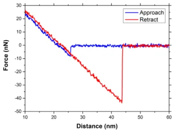
2.12 Approach / retract curve for an AFM tip. The approach is shown in blue, when the tip is close enough to the surface, it comes into contact with the sample. The withdrawal is shown in red. A greater force must be applied to detach the tip from the surface. This force curve is
taken by using full diamond tip on HOPG. . . 47
2.13 I–V characteristics measured on HOPG sample by using full diamond tip for (a) new tip (Rtip ≈ 460Ω), (b) tip after using it for 2 months (Rtip ≈ 460Ω). We can see the non-linearity in the I-V characteristic for used tip . . . 48
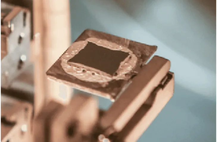
2.14 Sample holder where sample is glued to it using silver epoxy. . . 49
2.15 Topographical image taken by AFM for H f O2sample using full dia-mond tip. . . 49
2.16 A basic AFM unit inside ultra-high vacuum chamber connected to Keithley for electrical measurement. . . 51
2.17 Basic unit of a scanning electron microscope. . . 52
2.18 A SEM image of a new full diamond tip. . . 52
2.19 Schematic diagram for production of X-Ray. . . 53
2.20 EDX spectrum of multi-element glass (NIST K309) containing O,AL,Si,Ca,Ba and Fe (Goldstein et al: 2003)[283] . . . 53
3.1 I-V characteristics at low compliance for TiN/H f O2sample with full diamond tip (a) at 100nA, (b) at 200nA, (c) at 300nA and (d) at 400nA. 58 3.2 I-V characteristics at high compliance (300µA) for TiN/H f O2sample with full diamond tip showing forming, SET and RESET for different loops. In fig (b) the absolute current is plotted for both polarities. . . . 59
3.3 I-V characteristics at compliance current in the range of µA for TiN/H f O2 sample with full diamond tip (a) at 10µA, (b) 50µA, (c) 100µA, (d) 200µA, (e) 300µA, (f) 400µA, (g) 500µA and (h) 600µA. . . 61
3.4 I-V characteristics at compliance current in the range of µA for TiN/Ti/H f O2 sample with full diamond tip (a) at 10OµA, (b) 200µA, (c) 300µA, (d) 400µA, (e) 500µA and (f) 600µA. . . 62
3.5 I-V characteristics for linear on state conductance for TiN/H f O2 sam-ple with full diamond tip (a) at 450µA, (b) 475µA and (c) 500µA. . . 64
3.6 On and off state conductance variation with compliance current for (a) for TiN/H f O2& (b) for TiN/Ti/H f O2and 1µm21T1R (TiN/Ti/H f O2/Ti) devices[286]. . . 65
3.7 Filament growth inside oxide layer. The left figure is showing the filament in the beginning and right figure is showing the growth in the filament after reaching the compliance current. . . 66
3.8 The characteristic of the external apparatus considered in equation 3.7. 67 3.9 I-V characteristics at low compliance for TiNHfO2 sample with full diamond tip with simulated fits using the model designed for low compliance current (a) at 100nA, (b) at 200nA, (c) at 300nA and (d) at 400nA. . . 69
3.10 (a) Filament length evolution inside the oxide layer as a function of time. (b) Filament growth during voltage ramp. (c) Filament length evolution at different compliance currents and (d) Filament length at different compliance currents. . . 70
3.11 I-V characteristics at low compliance (in red) and at high compliance (in blue) for TiN/H f O2sample with full diamond tip in log scale. . . . 71
xvii
4.1 I-V characteristics for TiN/H f O2sample with sharp AFM tips (boron
doped full diamond (in red) and PtSi (in blue)) . . . 76 4.2 I-V characteristic for AFM tips on HOPG sample before and after
blunting it on H f O2sample. . . 78
4.3 (a) Forming, SET and RESET steps on TiN/H f O2sample with blunt
full diamond tip, (b) I-V characteristics with blunt full diamond AFM tip. Experimental data is the superposition of many loops, (c) I-V characteristics with blunt full diamond AFM tip for TiN/Ti/H f O2
after forming the filament by using pulses. . . 79 4.4 I-V characteristics for TiN/H f O2sample with (a) sharp AFM tips, (b)
blunt tip. . . 80 4.5 Topographical AFM images of H f O2surface (a) before I-V
measure-ment with sharp tip, (b) after I-V measuremeasure-ment with sharp tip, (c) be-fore I-V measurement with blunt tip & (d) after I-V measurements with blunt tip. A hillock like structure was detected after the I-V mea-surement. . . 81 4.6 (a) & (b) SEM Images of sharp and used blunt full diamond tip, (c) &
(d) EDX analysis of full diamond tip before and after electrical mea-surements on H f O2sample. The scan was done at two positions for
the sharp tip before the electrical measurements as shown in the im-age by red and blue dots corresponding to the color in graph (c), and in the case of the blunt tip after the electrical measurements, the scan was performed at four different (red, blue, orange and green) posi-tions corresponding to the color shown in graph (d) . . . 82 4.7 (a) Topographical AFM images of H f O2surface with new tip before
blunting (b) Topographical AFM images of H f O2 surface with blunt
tip around the area where tip was blunted. The area where the tips was blunted is shown inside red rectangle and two white lines repre-sent the profile taken to measure the roughness, (c) Roughness pro-files over the surface where tip was blunted as shown in fig (b) by line 1 & 2, (d) SEM EDX measurement of full diamond tip, which was blunted on the H f O−2 . . . 83 4.8 (a) Schematic representation of the array formation and its
localiza-tion on TiN/H f O2sample by using AFM, (b) SEM image of the area
where an array of hillocks is formed by forming the filament in TiN/H f O2
sample, (c) Lamella of the array of hillocks for TEM measurement pre-pared by FIB-SEM. . . 85 4.9 (a) TEM image of the lamella, (b) TEM image of the hillock. . . 86 4.10 (a) Filament formation in H f O2based device by using C-AFM at 400
µAcompliance current. (b) STEM image of the memory biased with
C-AFM and (c) STEM-EELS map of extracted Ti signal after forming. Ti migration can be seen in blue in the area boxed with dashed line. The figure is taken from reference[307]. . . 87 4.11 (a) STEM-HAADF image of the region where it is analyzed by EELS.
STEM-EELS map of the polarized memory with a compliance current of 400 µA (b) for nitrogen, (c) for titanium (d) for oxygen. Small Ti migration can be seen in figure (c). The figure is taken from Tristan DEWOLF’s PhD thesis[308]. . . 87 4.12 I-V characteristics and simulations for different bottom electrodes by
using full diamond blunt tip as top electrode in both cases. Experi-mental data is the superposition of many (around 10) loops. . . 88
4.13 ON State conductivity (Gon) variation with different bottom electrodes
at different compliance currents. (Red circle half down filled-Minimum value of Gon for TiN/Ti/H f O2, Red circle half up filled-Maximum
value of Gon for TiN/Ti/H f O2, Red circle full filled -Mean value of
Gon for TiN/Ti/H f O2, Blue hexagonal half down filled -Minimum
value of Gonfor TiN/H f O2, Blue hexagonal half up filled -Maximum
value of Gonfor TiN/H f O2, Blue hexagonal full filled -Mean value of
Gon for TiN/H f O2, Green star unfilled-Gon for 1T1R device13) (The
values of Gonfor TiN/Ti/H f O2is in Red, the value of Gonfor TiN/H f O2
is in Blue and the values of Gonfor 1T1R Devices are in Green . . . 89
4.14 Polarity effect for different samples. (a) I-V characteristic with Form-ing and SET in negative bias and RESET in positive bias, (b) I-V char-acteristic with Forming and SET in positive bias and RESET in neg-ative bias and (c) Both case (a) & (b) on same voltage. Experimental data is the superposition of many loops (10 loops) . . . 91 4.15 (a) AFM I-V characteristic comparison with 1T1R device
character-istic for TiN/H f O2 (b) Comparison of C-AFM and 1T1R device I-V
characteristic obtained on TiN/Ti/H f O2sample. Experimental data
is the superposition of many (around 10) loops. . . 92 4.16 (a) Series resistance effect on I-V characteristic for TiN/H f O2with a
series resistance of 1.1 kΩ. (b) Comparison between the characteristic obtained with and without series resistance on the same sample with same conditions. . . 93 4.17 (a) I-V characteristics for TiN/H f O2and TiN/Ti/H f O2sample with
series resistance of 1.1 kΩ, (b) I-V characteristics for TiN/H f O2 and
TiN/Ti/H f O2 sample after removing the series resistance of 1.1 kΩ
by using calculations . . . 94 4.18 I-V characteristic for TiN/H f O2 sample with series resistance. (a)
First 20 loops for SET and RESET, (b) Next 10 loops with little bit larger memory window, (c) Next 10 loops with even larger window and becoming constant, (d) SET and RESET loops after around 40 loops with constant memory window with reproducible I-V charac-teristic, (e) Experimental result fitted by simulation. . . 95 4.19 Schematic description of the model[286]for (a) device, (b) CAFM
mea-surements in the off state and polarized for set with blunt tip. Tox is
the H f O2 thickness and Sc the constriction cross section. The other
quantities are defined in the text and in table 4.1. . . 97 4.20 Schematic description for shifting of AFM tip for (a) sharp full
dia-mond tip, (b) blunt full diadia-mond tip. . . 101 4.21 (a) I-V characteristics with (a) sharp AFM tip, (b) I-V characteristics
with blunt full diamond AFM tip. Experimental data is the superpo-sition of many loops. (c) Schematic description of the model for sharp tip, (d) Schematic description of the model for blunt tip, (e) Barrier height model for sharp tip, (f) Barrier height model for blunt tip. . . 104 4.22 (a) AFM I-V characteristic comparison with 1T1R device characteristic
for TiN/H f O2(b) Comparison of C-AFM and 1T1R device I-V
char-acteristic obtained on TiN/Ti/HfO2 sample. Experimental data is the superposition of many (around 10) loops . . . 105 4.23 I-V characteristics and simulations for different bottom electrodes by
xix
4.24 I-V characteristic for TiN/HfO2 sample with series resistance and sim-ulated fit by using model. . . 107 5.1 Schematic representation of phase change in phase change material
for phase change memory[201]. . . 109
5.2 Typical current-voltage characteristic of GST-225 phase change mate-rial[195]. . . 110 5.3 Schematic diagram representing the measurement setup with
conduc-tive atomic force microscope (C-AFM) for phase change memory . . . 111 5.4 (a) I-V characteristic for Ge2Sb2Te5 (GST-225) sample by having full
diamond AFM tip as top electrode. (b) Zoom in of (a) near the phase transition. . . 112 5.5 I-V characteristic for Ge2Sb2Te5 (GST-225) sample by having full
dia-mond AFM tip as top electrode at different ramp speed for different voltage step size. (a) at 0.1 V, (b) at 0.05 V, (c) at 0.01 V and (d) com-parison of I-V characteristic at all the voltage step. . . 112 5.6 I-V characteristic of Ge2Sb2Te5 (GST-225) with full diamond AFM tip
as top electrode. (a) without capping layer of GeN, (b) with capping layer of GeN and (c) comparison between both samples. . . 114 5.7 I-V characteristic for GeSbTe-Theta (GSTθ) sample by having full
di-amond AFM tip as top electrode. (a) Without GeN capping layer, (b) with GeN capping layer and (c) comparison between both samples. . . 115 5.8 AFM topographical images of GST-225 without capping layer (a)
be-fore performing the electrical characterization, (b) after electrical char-acterizations, the white line represents the z-profile plotted in figure (d) and arrow represents the direction of the profile taken, (c) three-dimensional view of the image shown in figure (b), (d) the z-profile of the pit structures along the white line shown in figure (b). . . 116 5.9 AFM topographical images of GST-225 with capping layer GeN (a)
be-fore performing the electrical characterization, (b) after electrical char-acterizations, the white line represents the z-profile plotted in figure (d) and arrow represents the direction of the profile taken, (c) three-dimensional view of the image shown in figure (b), (d) the z-profiles of the pit structures along the white line shown in figure (b). . . 117 5.10 AFM topographical images of GSTθ without capping layer (a) before
performing the electrical characterization, (b) after electrical charac-terizations, the white line represents the z-profile plotted in figure (d) and arrow represents the direction of the profile taken, (c) three-dimensional view of the image shown in figure (b), (d) the z-profile of the pit structures along the white line shown in figure (b). . . 118 5.11 AFM topographical images of GSTθ with GeN capping layer (a)
be-fore performing the electrical characterization, (b) after electrical char-acterizations the white line represents the z-profile plotted in figure (d) and arrow represents the direction of the profile taken, (c) three-dimensional view of the image shown in figure (b), (d) the z-profile of the pit structures along the white line shown in figure (b). . . 119 5.12 Comparison for the I-V characteristic between GST-225 and GSTθ
sam-ples (a) without capping layer and (b) with capping layer. . . 120 5.13 Schematic used for geometric modelling in the FEM approach for
5.14 (a) I-V characteristic for phase change material with simulated fit ob-tained by different models for On-state and OFF state (a) for Ge2Sb2Te5
(GST-225), (b) GSTθ. . . 126 5.15 Resistivity versus temperature for GST-225 and Ge-rich GST (GSTθ)
thin films, showing the increase of the crystallization temperature with increasing Ge content(taken from reference[340]). . . 127 5.16 (a) AFM conductance image, (b) Topography image of crystallized
wire-array on a-GST film. Wires 1, 2, 3, 4, 5, and 6 were fabricated with bias voltages, -1, -2, -4, -6, -8, and -10 V, respectively, (c) and (d) show line profiles along the solid lines of wire 5 in (a) and (b), respec-tively (taken from reference[342]). . . 128 5.17 Temperature variation in the phase change material because of the
joule heating is shown in red. In green the crystallization temperature of GST-225 and in blue the crystallization temperature of GSTθ are given. . . 129 5.18 Simulation for GST-225 by using COMSOL Multiphysics c
consider-ing the model given by Wang et al. The model is showconsider-ing the phase transition from amorphous to crystalline. Blue color for GST layer is showing amorphous phase and dark red color is showing crystalline phase. (a) Simulation for GST with voltage ramp speed of 0.125V/s is given at 2s, for showing the whole system. Simulation for GST at different times is shown (b) at 2s, (c) 5s, (d), 10s, (e) 20s, (f) 30s. . . 131 5.19 Temperature variation in GST-225 (a) at 2 sec, (b) at 5 sec and (c) at 10
xxi
List of Tables
1.1 Comparison of conventional and emerging memories. The data is taken from reference[50]. 1D1R is one diode and one resistor unit cell. . 15
1.2 Different materials used for RRAM switching in literature. . . 20 1.3 Different materials used for top and bottom electrode in MIM
struc-ture for RRAM in literastruc-ture. . . 23 3.1 Primary study for switching in TiN/H f O2 and TiN/Ti/H f O2
sam-ple with different tips. (IC → ICompliance, VF → VForming, VS → VSET,
VR →VRESET, IR→ IRESET) . . . 57
3.2 Different parameters used for simulation to design the model for low compliance current. . . 68 4.1 Parameters values used in the model in order to fit the experimental
data. . . 100 4.2 Fitting parameters values used to simulate the switching
characteris-tics shown in figures 4.21a & 4.21b, 4.22, 4.23 & 4.24. The symbol∼ indicates that the fitted values are less accurate because of the large cycling fluctuations observed for sharp tips. . . 102 5.1 Phase change material sample description used to study the
charac-teristic in this chapter. . . 111 5.2 Different parameter values used for the GST-225 FEM model. . . 124 5.3 Different parameters used for Ielmini et al model to model the OFF
state of phase change materials. . . 125 5.4 Different parameters used for Navarro et al. model to model the ON
1
Introduction
Non–volatile memory technologies are an important part of the microelectronics in-dustry as they are the fundamental for any electronic system we interact with in our daily life. The growing market of the electronics for example digital cameras, smart phone, personal computer, solid state hard disk and many more, need continues improvement in performance and in functionalities.
For many decades flash technology is the main NVM technology used exten-sively in all electronics but many problems are arising for further scaling and in per-formances. Because of these problems, it is necessary to look for alternative solution which can replace flash technology as main NVM memory. Many new emerging non-volatile memories has been studied based on new concepts and new materials which can replace the current flash technology. Innovative approaches other than displacing and trapping electrons like in Flash memories have been investigated.
Magnetic random-access memory (MRAM), ferroelectric random-access mem-ory (FeRAM), Oxide based random-access memmem-ory (OxRAM) and phase change random-access memory (PCRAM) are some of emerging resistive non-volatile mem-ory which can potentially replace the Flash technology. These kinds of memories are generally based on two terminal devices, and have an active material sandwiched between two electrodes. The main idea of using this kind of structure and material is to use a specific physical mechanism allowing to switch it between two different resistive states for information storage.
For oxide based random-access memory (OxRAM), generally a conductive fila-ment is grown inside the oxide layer, linking the two electrodes due to which two stable state can be generated by creation and disruption of the conductive filament. For the phase change random-access memory (PCRAM), a chalcogenide material is used which can change its phase between a high resistive amorphous and a low re-sistive crystalline state. These are the two emerging memory technologies which are being studied a lot these days and are showing better performance in terms of read and write speed and also have low power consumption. Many research teams are working to improve the performances and to understand the mechanism behind the switching clearly. The switching mechanism in OxRAM is still a debatable topic and many theories have been provided.
In this thesis, we will study these two different technologies (OxRAM & PCRAM) to understand the mechanism behind switching at nanoscale and to see the scalabil-ity by using conductive atomic force microscopy (C-AFM) in ultra-high vacuum. A detailed study for H f O2based OxRAM will be presented showing effects on
resis-tive switching due to different bottom electrode material, different AFM tip material and compliance currents by performing electrical characterization. For PCRAM, a study based on GeSbTe (GST) material will be presented. Electrical characterization will be performed to see the phase change.
In chapter1, a general overview of non-volatile memory technologies will be pre-sented. Different technologies will be briefly discussed and will be compared to each other in terms of improvements. After providing a brief overview of all the volatile and non-volatile memory technologies, a comprehensive review will be provided for OxRAM and PCRAM. Different materials, their performance and challenges as well as different switching mechanisms provided in literature will be discussed in detail for both technologies. In the end a state of art will be presented for the motivation of this thesis work.
In chapter2, different experimental techniques used to study these memory tech-nologies will be presented. As C-AFM is used as probe station to characterize them, a general overview of atomic force microscopy will be discussed. Also, different C-AFM tips used for electrical characterization of memories as well as different AFM scanning techniques will be discussed. All the characterization will be done in ultra-high vacuum, so the setup will also be presented briefly. A brief overview of scanning electron microscope (SEM) and SEM-EDX (energy-dispersive X-ray spec-troscopy) will also be presented as these techniques will be used to characterize the C-AFM tips after having used them for performing the electrical characterization.
Chapter3 is focused on H f O2 based OxRAM. Resistive switching in this kind
of memory will be presented and its dependence on compliance current will be dis-cussed. First of all, a general study to know the nature of switching behavior (bipo-lar, unipolar or non-polar) will be performed. Once the switching nature for dif-ferent H f O2 based samples determined, a detailed study will be performed in two
different compliance current regimes, the nA and the µA range. In both regimes, I-V characteristics will be studied to determine the impact of compliance current on memory effect and the ON state conductance. The results obtained by C-AFM will be compared to device characteristics. To understand the experimental results, an analytical model of filament growth in nA regime will be discussed. A more de-tailed study in µA regime will be presented in chapter4.
In chapter4, a detailed study of resistive switching in high compliance current regime (µA) for H f O2 based OxRAM will be presented. First of all, the effect of
C-AFM tip material (PtSi and full diamond) on resistive switching will be discussed as AFM tips are used as top electrode. Also, the effect of tip radius will be discussed as the tip-sample contact area depends on it. Full diamond tips will be blunted to increase their diameter from 10-20 nm to around 100 nm in order to study its impact. I-V characteristics with sharp and blunt tips will be compared. Also, topographical study will be performed in order to see the deformation on the H f O2surface after
electrical characterization. SEM-EDX study will be performed to see the chemical composition of the tip before and after the electrical characterization. A brief TEM analysis of the deformation (hillocks) of the H f O2 surface will be done in order to
know its composition. The impact of bottom electrode material on resistive switch-ing will also be studied. All the results obtained by C-AFM will be compared to 1T1R devices in terms of conductance. In the end, effect of polarity on forming and resis-tance switching will also be discussed. A model based on metallic filament growth will be discussed and will be compared to the experimental results.
Chapter 5 is focused on PCRAM memory. A brief introduction about phase change in phase change materials will be provided. Different phase change ma-terials studied will be discussed. By using C-AFM setup, phase change from amor-phous to crystalline will be studied in GST-225 and Ge rich GST. Analytical models
3
for On-state (crystalline state) and off state (amorphous state) conductance will be discussed. Also, a finite element method approach for phase change in GST-225 will be given. In the end, experimental results obtained by C-AFM will be compared with these models.
Finally, a general conclusion of this work, summarizing the main results will be provided. Also, the highlights and the perspectives of this research for both tech-nologies studied will be given.
5
Chapter 1
Memory Landscape and Emerging
Technologies
In this chapter, an overview of different memory technologies is provided. They will be briefly discussed and compared in terms of their strengths and areas for im-provement. This chapter is focused on emerging non-volatile memories especially oxide resistive random-access memories (OxRAM) with an emphasis on H f O2as the
active layer and phase change memories (PCM) with an emphasis on GST as chalco-genide material. This chapter will comprehensively review OxRAMs and PCM from materials point of view to their performance and the physical mechanisms behind their operation. Different mechanisms given in literature for Oxide based Random access memory will also be discussed briefly.
FIGURE1.1: Overview of different memory technologies[1]. 4F2 rep-resents the cell dimension where F is the minimum feature size.
1.1
Overview of memory technology
Normally, memory technologies are divided into two main categories according to their ability to maintain the information without supply voltage, Volatile memories and non-volatile memories. Two different technologies for Volatile memories are well known which are the Static random-access memory (SRAM) and the Dynamic random-access memory (DRAM). Volatile memories lose their data when power is turned off, non-volatile memories don’t. There are many different technologies which belong to the non-volatile group like Flash, NOR, NAND and some emerging technologies like, RRAM, PCM, MRAM, etc. An overview of memory technologies is shown in figure1.1. The memory cell dimension is generally presented in terms of F2where F is the minimum feature size. The minimum feature size (F) is the size or the width at which a transistor or any type of device on the silicon surface can be drawn at.
1.1.1 Volatile Memories Static random-access memory
The word static indicates that the information stored in the memory does not have to be refreshed periodically. However, data is lost when power is switched off due to the volatile nature. SRAMs generally use a matrix of six transistors and no capac-itors to store information (shown in figure1.2). They present very fast Read/write speeds (1ns/1ns) and excellent endurance[2]. However, they are expensive and have low density integration because of their larger feature size (24F2)[2]. They are gen-erally used as cache in computer systems. This type of memory has low power consumption.
FIGURE1.2: A typical cell structure of SRAM memory.
Dynamic random-access memory
DRAM, unlike SRAM, must be refreshed in order to maintain their data. This is done by placing the memory on a refresh circuit that rewrites the data several hundred times per second. DRAM is used for most memory systems because it is cheap and small. DRAMs consist of one transistor and one capacitor (1T1C) to store informa-tion as shown in figure1.3. The presence of charge at the terminals of the capacitor corresponds to Logic “1” while Logic “0” corresponds to the absence of charge. Due
1.1. Overview of memory technology 7
to its smaller feature size (6-8F2)[2], this technology is cheap and presents a very high
integration density level with very excellent endurance. DRAMs are generally used as main memory in computer RAMs. DRAM consumes more power and is slower compared to SRAM. A Micron Technology MT4C1021 DRAM integrated circuit is shown in figure1.4.
FIGURE1.3: A typical cell structure of DRAM memory.
FIGURE1.4: A die photograph of the Micron Technology MT4C1021 DRAM integrated circuit.
1.1.2 Nonvolatile memories
These kinds of memory technology do not lose data after turning off the power like SRAM and DRAM. Over past few decades, Flash is often used as the non-volatile memory. This memory technology benefits from the traditional scaling of semicon-ductor industry allowing the high-density integration for mass production. How-ever, the scaling limit is approaching to end due to serious problems such as floating gate interface, lower coupling ratio, leakage current due to thinner oxide layer, short channel effect and low electron charge in the floating gate[3]. After these limitations became critical in flash technology, some new technologies are needed which can scale down without having any effect of the problems discussed for Flash. Hence,
alternative solutions are being discovered referred as emerging non-volatile memo-ries[1;4–6]. There are many different kinds of emerging non-volatile memories such as Ferroelectric random-access memory (FeRAM), Magnetic random-access memory (MRAM), Phase change random access memory (PCRAM) or simply phase change memory (PCM), Conductive bridge random access memory (CBRAM) and oxide based random access memory (OxRAM). Some of them are already commercially available in market like PCM and MRAM. All these memories will be discussed briefly in next section. A comparison of different memory type cell structures is presented in figure1.5.
FIGURE1.5: Comparison of different cell structures for different types of memory technology[4].
1.2
Emerging nonvolatile memory technologies
1.2.1 FlashFlash memory is a nonvolatile storage device that can be erased and reprogrammed. Flash memory was developed from electrically erasable programmable read only memory (EEPROM). There are two different types of Flash memory based on logic gates, NAND and NOR Flash memory. The internal characteristics of different types of flash memory cells exhibit characteristics similar to the corresponding gates. The NAND type is primarily used in main memory, memory card, USB flash drives, solid state drives for general storage and transfer of the data. The NOR type is used as a replacement for the older EPROM and alternative to certain kind of ROM applications.
In 1967, Kahng et al. presented the floating gate and its application for memory in their paper[7]. Flash memory was invented by Dr Fujio Masuoka while working in Toshiba in 1980. Mausoka et al. presented the invention at the IEEE 1984 Interna-tional Electron device meeting held in San Francisco[8;9]. Intel first commercialized the NOR type Flash memory chip in 1988.
Flash memory cell[10] is a typical floating gate MOS transistor, and this float-ing gate (FG) is completely surrounded by dielectric or oxide layer, and electrically governed by a capacitively coupled control gate (CG)[4;11]. This floating gate is elec-trically isolated from the control gate and the channel by two dielectric layers: con-trol oxide and tunnel oxide. Being electrically isolated, the floating gate acts as the
1.2. Emerging nonvolatile memory technologies 9
storing electrode of the cell. When a positive voltage is applied to the control gate, electrons are injected into the floating gate through the tunnel oxide via Fowler-Nordheim (FN) tunneling. The Logic state is represented by the charging level. The neutral or positively charged state is associated with logic state “1” and the nega-tively charged state corresponds to logic state “0”.
FIGURE1.6: (left) Basic structure of Flash memory cell (right) Exam-ple of corresponding IV characteristics; adopted from[12].
Flash has two different kind of architectures based on gate, NOR and NAND arrays, which are named after the resemblance to the pull-down networks in the corresponding CMOS logic gates. In the NOR array, cells are organized in a parallel architecture, aiming at a direct access of each cell, which is connected to its bit line through a dedicated drain contact enabling the device to achieve random access. Because of this parallel architecture the performance is better for NOR. This con-figuration enables the short-read times required for random access microprocessor instructions. NOR flash is ideal for lower density, high speed-read applications.
NAND flash was developed as an alternative optimized for high density data storage, giving up random access capability in a trade of smaller cell size. This was done by creating memory cells connected in series and organized into memory strings, trading off read/write random speed for a higher integration density and, thus, a lower cost per bit[13–15]. So, NAND flash is ideal for low cost, high density
and high-speed program/erase application. The architecture comparison between NAND and NOR flash is given in figure1.7.
Over past years many improvements were done in flash technology. Flash tech-nology has been scaled down in order to meet the requirement of reduced feature size and large memory. Intel started the mass production of 32-layed NAND chips as shown in figure1.8. When reaching the scaling limit of transistors, some alter-native technologies have to be developed. Even after a remarkable development in the field of flash, it is believed that scaling beyond 22nm node will be challeng-ing and serious physical problems will appear[17]. In order to have 10-year data retention, the tunnel and control oxide need to be thick enough to prevent charge loss. But scaling down the thickness of tunnel oxide will affect this requirement. The primary concern is that stress Induced leakage current (SILC) affects the device reliability and its amplitude increases when reducing the oxide thickness[18]. Also,
FIGURE1.7: Comparison of NOR Flash array and NAND Flash array architectures[4].
FIGURE1.8: 32-layer 3D NAND Flash produced by Intel[16].
few electron phenomena may be an ultimate intrinsic limit in the scaling of Flash memories[19].
Currently, an extensive research is going in the field of memory and it is not easy to predict which technology will win the race. Even though there are many technologies which are showing the great interest in the field of memory and will be discussed in coming sections.
1.2.2 FeRAM
Ferroelectric random access memory[20;21](FeRAM) is a type of non-volatile memory
which uses ferroelectric layer as a capacitor to store the data. It uses the ferroelectric effect for the storage mechanism. It is polarized by applying external electric field and remains polarized even if the external electric field is removed. This type of polarization is called remanent polarization. Due to this polarization characteristic,
1.2. Emerging nonvolatile memory technologies 11
FeRAM does not lose any data if the power is removed from it. When the direction of the applied field is reversed, the polarization of the ferroelectric material changes its direction and hence, it can update the new data. Polarization is a phenomenon due to the ionic displacement of atoms of ferroelectric crystal structure.
FIGURE 1.9: On left hand, the basic structure of a FeRAM cell is shown. On top right crystal structure of ferroelectric and on bottom right an electric polarization-electric field hysteresis curve are also
shown[4].
Therefore, FeRAM is a superior memory that has fast speed of reading and writ-ing the data. It has low power consumption among other semiconductor memo-ries[22]and higher operation speed compared to DRAM[23;24]. So, it is a fast memory that can endure a high number of cycles (for example 1014)[25]. The idea of ferroelec-tric memory was first given by Bell Laboratory in 1955. In 1980, a FeRAM in which data is stored by polarization direction in ferroelectric capacitors and read out by using reverse polarization direction was proposed[26]. A FeRAM memory cell has the same structure as a DRAM cell and consists of a transistor and a capacitor, but in this case the FeRAM cell contains a capacitor with a ferroelectric dielectric.
This kind of memory is fabricated by depositing a film of ferroelectric material in crystalline form between two electrode plates to form a capacitor. This structure is similar to that of the DRAM capacitor. It is important that the ferroelectric films should have high remanent polarization, low leakage current, low coercive field. Low operating voltage is reached because of the low coercive field which also helps in faster switching speed and better fatigue resistance. Today’s FeRAM uses lead zir-conate titanate (PZT); other materials are being considered. FeRAM are extensively studied. Even after FeRAM has achieved a level of commercial success, with the first devices released in 1993[27]. Since 2011 there are new promising development with
H f O2based materials which present ferroelectricity[28].
1.2.3 MRAM
Magnetic Random access memory is also nonvolatile memory[29] but it works on
magnetic field unlike other nonvolatile memories like flash which work on charge storage. It uses a magnetic element having a magnetoresistance effect in a memory cell. Magnetoresistance effect is a phenomenon which happens when a magnetic
field is applied to magnetic material and its electrical resistance is changed in accor-dance with the direction of its magnetization.
FIGURE1.10: Simple structure of a magnetic tunnel junction is shown in the left side and variation in resistance with magnetic field is shown in the right side with two different magnetic states, the
par-allel one and the anti-parpar-allel one[30].
The basic MRAM cell element consists of a magnetic tunnel junction (MTJ) as shown in figure1.11. Magnetic field induced magnetic switching was first employed in the early realization of MTJ based MRAM[30–32]. These MTJs are composed of three different layers. One layer is insulating layer which is sandwiched between two magnetic layers, called free magnetic layer[33] and fixed magnetic layer. Elec-trons in MTJs which are spin polarized by magnetic layer traverse the dielectric bar-rier through tunneling[34]when a bias is applied. These MTJs devices have low re-sistance when the magnetic moment of the free magnetic layer is parallel to the fixed magnetic layer and have high resistance state when they are in antiparallel state.
FIGURE1.11: Schematic of 1-transistor, 1-MTJ cell.
1.2. Emerging nonvolatile memory technologies 13
to induce the magnetic field for switching, but with the development in the field of MRAM, the write current level[35] decreased. For example, devices based on STT-MRAM (Spin transfer torque-MRAM)/MRAM have high endurance and high-performance characteristics (high speed, low voltage) which makes them good can-didates for embedded applications. On the other hand, MRAM has low integration density compared to Flash or DRAM[35] and its scalability beyond the 20nm node still remains to be demonstrated[36].
1.2.4 CBRAM
One of non-volatile memory is conductive-bridging random access memory (CBRAM)[37;38] which is based on metal ion transport and redox reactions to form a persistent con-ducting filament in a high resistance film between two electrodes. The switching is based on formation and dissolution of this metallic filament in the material under external bias. CBRAM consists of an inert electrode like platinum, iridium, gold or tungsten and the other electrode can oxidize such as copper or silver. This effect may be reversed to return the device to a high resistance state. These two electrodes are separated by a solid electrolyte or oxide material[39;40]. Memory Switching using a
Ag dendrite in a Ag-doped As2S3 film in a Ag/As2S3/Mo structure is reported by
Hirose et al.[41]in 1976. The On state is achieved by applying a positive bias at the oxidizable anode resulting in the redox reaction driving the positive silver ions to the inert cathode if the electrode is of silver. Due to this effect, a filament of metal rich clusters is formed leading to a conductive bridge between the electrodes. By ap-plying the opposite voltage, the filament can be dissolved breaking the conductive bridge between the electrodes.
FIGURE1.12: Schematic illustration of the CBRAM switching mech-anism[42].
The CBRAM memory is also known as programmable metallization cell (PMC). In 1999, Kozicki et al.[43]reported a programmable metallization cell (PMC) device using metal-doped chalcogenide films. PMC devices are also called electrochemical metallization cell (ECM)[44;45], atom switch[46], or CBRAM[42;47].
FIGURE1.13: Typical I-V characteristic of Ag/Ag-Ge-Se/Pt electro-chemical metallization cell. Adopted from reference[48].
1.2.5 PCRAM
Phase change memory (PCM) or Phase change random access memory (PCRAM) is the most matured technology among the emerging non-volatile memories. Phase change memory is based on the phase change of the active material. Generally, chalcogenide materials are used as a phase change material. Chalcogenide mate-rials are in amorphous phase initially and can change the phase to crystalline by applying a bias. The on state corresponds to the low resistance state due to crys-talline phase and the Off state to the high resistance state of the amorphous state. A schematic structure for PCM is presented in figure1.14. This type of memory will be discussed in more detail in section1.4.
1.2. Emerging nonvolatile memory technologies 15 T ype SRAM DRAM NOR FLASH NAND Flash MRAM PCRAM FeRAM RRAM Cell elements 6T 1T1C 1T 1T 1(2)T1R 1T1R or ID1R 1T1C 1T1R or ID1R Cell Latch Stack/ tr ench capacitor Floating gate/ change trap Floating gate/ change trap Magneto resistance Phase change Polarization change Resistance change Minimum / cell size n m 2 140 F 2 6 F 2 10 F 2 5 F 2 20 F 2 4 F 2 22 F 2 4 F 2 W rite/ erase time 0.3 ns/0.3ns <10 ns/<10 ns 1 ms/10ms 1ms/0.1ms 10 ns/10 ns 20 ns/50 ns 10 ns/10 ns 5 ns/5ns Endurance (cycles) >3 × 10 16 >3 × 10 16 >10 5 >10 5 >3 × 10 16 >10 8 >10 14 >10 10 Application Cache Main memory Storage Storage Storage Storage Storage Storage/ Main memory T A B L E 1 .1 : Comparison of conventional and emer ging memories. The data is taken fr om refer ence [ 50 ]. 1D1R is one diode and one resistor unit cell.
1.2.6 OxRAM
Oxide based random access memories (OxRAM) belong to resistive random-access memories (RRAM) and are also well known emerging non-volatile memories. An intensive research is going on for OxRAM. OxRAM has a high switching speed, low power consumption and is scalable. The basic structure of OxRAM is MIM (metal/insulator/metal). When a bias is applied a filament is formed inside the oxide layer connecting the two electrodes changing the resistance state. When the two metal electrodes are not connected through a filament, it is in high resistance state (HRS) which is also known as off state. When the two electrodes are connected through a filament, the low resistance state is achieved, this state is also known as On state. OxRAM will be discussed in detail in section1.3.
A comparison is provided for all the volatile and non-volatile memories dis-cussed in previous sections in table 1.1. Cell structure, minimum cell size, write and erase time as well as the number of endurance cycles for different memory tech-nologies are presented in the table1.1.
1.3
Oxide based random access memory
The resistive switching effect has been studied for more than 40 years. In 1962, Hick-mott et al.[51]reported resistive switching for the first time in the I-V characteristic of five metal oxide metal structures: SiOx, Al2O3, Ta2O5, ZrO2and TiO2. The
switch-ing time[51] was evaluated to be less than 0.5 µs. Still the mechanism of resistive switching was unclear. In 1964, Gibbons et al.[53] reported a study on NiO, where they believed that the switching is due to the formation and rupture of a Nickel filament in NiO thin film which is sandwiched between two electrodes. In 1967, Simmons et al.[54] reported the pioneering study discussing the use of this resis-tive switching for memory application[55]. In 1970, fast switching of resistance in Al/SiOx/Au structure was shown by Dearnaley et al.[56]and they concluded that
the reason was an electronic effect rather than the filament formation and rupture. Also, a paper published by Chua et at.[57] on “Memristor-the missing circuit
ele-ment” contributed to this field. ‘ Many studies have been done over the years on non-volatile memories from the 1960s to the beginning of the 21st century[58;59]and a 64-bit perovskite oxide-based ReRAM memory was fabricated by Zhuang et al.[60] in 2002 by using a 0.5 µm CMOS process. In 2004 a group from Samsung Advanced Institute of Technology reported binary transition metal oxide-based ReRAM and successfully demonstrated RRAM operation below 3V and 2mA, 106 set/reset op-erations and 1012 reading cycles[61]. A paper title “Missing memristor found” trig-gered the intensive development in RRAM[62]. Since then, great achievement had been reported in the field of RRAM by Unity[63], SanDisk/Toshiba[64], Micron/-Sony[65] and IMECAS[66]. Also, TSMC announced in 2017 a new plan to start the
production of embedded RRAM chips in 2019 based on 22-nm process. A roadmap for OxRAM is shown in figure1.15.
1.3.1 Basic Operation of OxRAM
As discussed in the previous section, the resistive switching mechanism in OxRAMs is still under debate. C. Cagli et al.[67]studied the switching in HfO2 based OxRAM devices. They did several experiments to demonstrate that the switching is driven by creation/disruption of a conductive filament (CF). They reported the resistance
1.3. Oxide based random access memory 17
FIGURE1.15: Historical timeline of RRAM development from 1962 to 2017. Adopted from[52].
variation as a function of cell dimension as shown in figure1.16. As it can be seen, there is no influence of cell dimension on the resistance in low resistance state (LRS) or On state, but the resistance should decrease with increasing the cell dimension ac-cording to the cross sectional area law. This clearly indicates that switching is driven by creation/disruption of a conductive filament. Also, there is small fluctuation in high resistance state (HRS) or off state. These fluctuations may be due to tunneling enhanced by partially disrupted filaments with different lengths. According to the independence of resistances to devices area, C. Cagli et al. suggested that the switch-ing is due to the creation and disruption of the filament. So, in this thesis, we will verify this assumption by using C-AFM measurements at nanoscale.
In pristine state, the resistance of the oxide layer is very high and it needs to be preconditioned before resistive switching. To precondition the resistance of pristine oxide an operation called forming is done. Forming is current controlled break-down of the oxide layer which creates a conductive path with low resistance called conductive filament (CF) inside the oxide layer connecting the two electrodes.
Once the conductive filament is formed, the resistance across the electrodes de-creases rapidly. When forming the filament, the current is limited to a value called