HAL Id: tel-02003297
https://tel.archives-ouvertes.fr/tel-02003297
Submitted on 1 Feb 2019HAL is a multi-disciplinary open access archive for the deposit and dissemination of sci-entific research documents, whether they are pub-lished or not. The documents may come from teaching and research institutions in France or abroad, or from public or private research centers.
L’archive ouverte pluridisciplinaire HAL, est destinée au dépôt et à la diffusion de documents scientifiques de niveau recherche, publiés ou non, émanant des établissements d’enseignement et de recherche français ou étrangers, des laboratoires publics ou privés.
electrochemical storage applications
Harish Banda
To cite this version:
Harish Banda. Development of graphene-based composite materials for electrochemical storage ap-plications. Material chemistry. Université Grenoble Alpes, 2018. English. �NNT : 2018GREAV023�. �tel-02003297�
Pour obtenir le grade de
DOCTEUR DE LA COMMUNAUTE UNIVERSITE
GRENOBLE ALPES
Spécialité : Chimie Physique Moléculaire et Structurale
Arrêté ministériel : 25 mai 2016
Présentée par
Harish BANDA
Thèse dirigée par Lionel DUBOIS, Chercheur, CEA Grenoble, et codirigée par Florence DUCLAIROIR, Chercheure, CEA
Grenoble
préparée au sein du Laboratoire de Systèmes Moléculaires et Nanomatériaux pour l’Energie et la Santé
dans l'École Doctoral Chimie et Sciences du Vivant
Développement de matériaux
composites à base de graphène pour
des applications en stockage
électrochimique
Development of graphene-based
composite materials for
electrochemical storage applications
Thèse soutenue publiquement le 19 octobre 2018 devant le jury composé de :
Madame Encarnacion, RAYMUNDO
Directrice de Recherche CNRS, CEMHTI Orléans, Rapporteur Monsieur Daniel, BELANGER
Professeur, Université du Québec à Montréal, Rapporteur Madame Fannie, ALLOIN
Directrice de Recherche CNRS, Université de Grenoble Alpes-LEPMI, Président
Monsieur Patrice, SIMON
Professeur, Université de Toulouse-CIRIMAT, Examinateur Monsieur Lionel, DUBOIS
Chercheur CEA, SyMMES, CEA Grenoble, Directeur de thèse Madame Florence, DUCLAIROIR
A quiet and modest life brings more happiness than the pursuit of success and the constant restlessness that comes with it.
I would like to express my special appreciation and hearty gratitude to my supervisors Dr. Florence Duclairoir and Dr. Lionel Dubois for giving me this opportunity to work under their supervision. I enjoyed working with both of you and I have progressed a lot professionally and personally. I greatly value the scientific freedom that both of you have given me and I thank you for the support and guidance during the tough times.
I would like to make a special mention of Florence for having been the main supervisor and providing everything that I needed to succeed academically. I am grateful for all those long discussions about ideas/avenues and the later hours in digging out what is interesting to publish. I owe you a ton of gratitude for helping me in overcoming administrative hurdles and the never-ending paper-work all through the French bureaucracy. I cherish the endless texts, calls, messages and hangouts that we have had at all points of a day/week or even during the vacations.
I would like to thank Prof. Daniel Belanger and Dr. Encarnacion Raymundo-Pinero for their time and effort in reviewing my thesis manuscript and Prof. Patrice Simon and Dr. Fannie Alloin for being part of my defense jury. I enjoyed the discussions during the defense and thank you all for the valuable advises and suggestions. I would like to thank CEA for funding my thesis and Institute for Nanoscience and Cryogenics (INAC) for hosting me. I convey my sincere thanks to Dr. Frederic Chandezon for his leadership and support.
I would like to acknowledge our collaborators Prof. Patrice Simon, Dr. Pierre-Louis Taberna and Barbara Daffos from CIRIMAT, Toulouse and Dr. Olivier Crosnier from IMN, Nantes for the fruitful discussions and constant support. I particularly thank Pierre-Louis for his scientific support, encouragement and excellent attitude towards everything. I thank Dr. David Aradilla Dr. Anass Benayad and Dr. Stephanie Pouget for their unwavering assistance and kind understanding all through my thesis. I convey my special thanks to Dr. Gerard Bidan for the positive spirit, excellent suggestions and for the continued encouragement.
I would like to thank Dr. Daniel Lee and Dr. Gael De Paepe for their can-do attitude and great deal of positivity. I acknowledge the support form Charles, Zohra and Sarah for their administrative assistance. I thank my colleagues at CAMPE and SyMMES for a friendly and cordial working environment.
certainly learnt a lot from you including swimming, fishing, hunting crystals & mushrooms, cementing walls, making pasta and so on. I enjoyed learning these life skills and will certainly carry on these in to my life hereafter. Johan, it was so much fun to have you around. It was you that has brought in the office coffee-culture into the lab and I feel that I get undeserved credit for that. Regardless, it was amazing to have had so many discussions and have shared many more beers at the Bristrot d’Emile. Sandy, I cannot thank you enough for a super work-attitude and efficiency that you have brought to me in the last one year. I appreciate your amazing patience in putting up with my poor management style. All in all, I must mention, we were a good team and I will miss that.
I would like to thank Chady, Fanny, Romain and Seydou for advising me with their experience and guidance about the hard PhD life. I thank Jeremy, Julia, Coralie, Laura, Marc, Aditya, Guillaume, Elena, Celine, Jordan and Friaume for all the fun at the lunches, bars, dinners, barbeques and all over Grenoble! Tugce, I thank you for the humour and positive attitude. It’s a pity that we didn’t know each other for almost a year but then, god bless the Global Young Scientists Summit in Singapore for making things right. I thank my friends Vinil, Ramesh, Ashok and Ajay for all the encouragement, support and understanding all through the tough times (ధన్యవాదాలు మిత్రులారా).
I thank the Trippers; Sarang, Prasanna, Ram, Sumanth, Rathod, Gali, Siva and Daniel for the amazing five years at IISER and the continued friendship and support ever after (धन्यवाद दोस्ोों). It gives me great comfort in knowing that you are always there. I thank Gourab, Cinzia, Push, Shashank, Keerthi, Aditya, Ritesh, Nishit and Arindham for making my Grenoble life an enjoyable one.
I express my heartfelt gratitude towards all my family members and all well-wishers. Finally, I thank my parents and brother & sister-in law for their constant support, confidence and understanding all through my career and especially during the PhD.
నేన్ు నా కుట ుంబ సభ్యయలకు (బుండ మరియయ కర్క) మరియయశ్రేయోభిలాషరలకు వారి మద్దత్ర కోసుం కృత్జ్ఞత్లు
తెలియజ్ేసుునాాన్ు. మయఖ్యుంగా, నా త్లిిద్ుండరులు మద్దత్ర మరియయ విశ్ాాసుం నా ప్ుయతాాలలో గొప్పగా
సహాయప్డ ుంది. నేన్ు ఈ నిర్ుంత్ర్ మద్దత్ర కోసుం వారికి నా కృత్జ్ఞత్లు తెలియజ్ేసుునాాన్ు. చిన్ానాటి న్ుుండ సహాయుం కోసుం నా తాత్, అమమమమ మరియయ మధు అన్ాలకు నేన్ు ప్ుతయయకుంగా కృత్జ్ఞత్లు తెలుప్ుత్రనాాన్ు.
SCs: Supercapacitors
EDLC: Electrical Double Layer Capacitor 2D: Two-Dimensional
3D: Three-Dimensional AC: Activated Carbon
CDC: Carbide-Derived Carbon CNT: Carbon Nanotubes GO: Graphene Oxide
RGO: Reduced Graphene Oxide GHs: Graphene Hydrogels
RPs: Reduced Pillar Graphene Materials CVD: Chemical Vapor Deposition
FT-IR: Fourier Transform – Infrared TGA: Thermal Gravimetric Analysis XRD: X-Ray Diffraction
XPS: X-Ray Photoelectron Spectroscopy SEM: Scanning Electron Microscopy BET: Brunauer-Emmett-Teller method DFT: Density Functional Theory SSA: Specific Surface Area
EIS: Electrochemical Impedance Spectroscopy TAABF4: Tetraalkylammonium tetrafluoroborate
General Introduction ... 2
Chapter I. Bibliography ... 10
1. Supercapacitors ... 10
1.1 Interest in Supercapacitors ... 10
1.2 Basics of Supercapacitors ... 13
1.3 Fundamentals of Electrical Double Layer Capacitors ... 17
2. Cell Design Characteristics for SCs ... 22
2.1 Electrolytes ... 24
2.2 Electrode Materials ... 29
2.3 Graphene-based Materials for SCs ... 35
3. Role of Pore Sizes on Charge Storage ... 47
3.1 Ion Sorption in Micropores ... 47
3.2 Ion Desovlation in Micropores ... 50
3.3 Hierarchical Porosity ... 51
4. Context & Objectives ... 53
4.1 Current Theme of Graphene Research for SCs ... 53
4.2 Our Proposed Theme of Graphene Research for SCs ... 53
4.3 Recent Reports in the Proposed Theme ... 54
4.4 Synthesis of Ion Accessible Inter-Layer Graphene Galleries ... 56
4.5 Proposed Methodology ... 56
5. References ... 60
Chapter II. Study of Graphene Hydrogels Self-Assembled with Short Alkyl Diamines ... 72
1. Objectives & Approach ... 72
2. Introduction ... 75
4. Conclusions ... 95
5. Further Conclusions & Perspectives ... 96
6. References ... 98
Chapter III. Study of Graphene Materials with Long Alkyl Diamines as Pillars ... 104
1. Objectives & Approach ... 104
2. Introduction ... 108
3. Materials & Characterization ... 110
3.1 Material Design ... 110
3.2 Characterization ... 111
4. Electrochemical studies ... 117
5. Conclusion ... 125
6. Further Conclusions & perspectives ... 126
7. References ... 129
Chapter IV. Electrochemical Impedance Analysis of Ion Transport in Pillared Graphene Materials ... 136
1. Objectives & Approach ... 136
2. Introduction ... 140
3. Results & Discussion ... 142
4. Conclusions ... 158
5. Further Conclusions & Perspectives ... 159
6. References ... 160
Chapter V. Study of Pillared Graphene Materials with Optimized Pillar Densities for SCs ... 166
1. Objectives & Approach ... 166
2. Introduction ... 170
4.1 Ion-sieving ... 182
4.2 Impedance Analyses ... 183
4.3 Power Capability & Volumetric Performances ... 188
5. Conclusions ... 193
6. Further Conclusions & Perspectives ... 194
7. References ... 196
Chapter VI. General Conclusions & Perspectives ... 202
1. Pillared Graphene Materials ... 202
1.1 Pillared Graphene Materials Limit Graphitic Restacking ... 202
1.2 Pillared Graphene Hydrogels with 3D structures ... 202
2. Electrochemical Analysis in SCs ... 203
2.1 Role of Alkyl Diamine Pillars ... 203
2.2 Role of 3D Macroscale Assemblies ... 204
3. Perspectives ... 206
Chapter VII. Materials and Methods ... 212
1. Common Materials ... 212
1.1 Graphene Oxide (GO) ... 212
1.2 Commercial Activated Carbon... 213
1.3 Electrolytes ... 214
2. Instrumentation Details ... 215
2.1 Characterization Techniques ... 215
2.2 Electrochemical Techniques ... 217
3. Experimental Details from Chapter II ... 218
3.1 Synthesis of Graphene Hydrogels (GHs) ... 218
3.4 Electrochemical measurements ... 221
4. Experimental Details from Chapter III ... 223
4.1 Synthesis of Reduced Pillared Graphene Materials (RPs) ... 223
4.2 Electrochemical Analysis ... 224
5. Experimental Details from Chapter IV... 226
5.1 Synthesis of Pillared Graphene Hydrogel (6 GH) ... 226
5.2 Electrochemical Analysis ... 226
6. Experimental Details from Chapter V... 228
6.1 Reduced Pillared Graphene Materials with Varied Equivalents ... 228
6.2 Pillared Graphene Hydrogels with Varied Equivalents ... 228
6.3 Electrochemical Analysis ... 229
7. References ... 229
Annex: Electrochemical Characterization of SCs... 234
2
General Introduction
Climate change and dwindling fossil fuels are among the major challenges that our societies are currently facing.1 The increasing demand for energy from growing populations and higher standards of living is resulting in rapid consumption of the limited fossil fuels. Additionally, the burning of fossil fuels for energy production also produces large amounts of toxic SOx, NOx gases along with other greenhouse gasses such as CO2 and CH4.2 Although energy security is at the core of the issue, the impact of the energy policies extends into far reaching realms of environment, health, jobs, and economic costs. As a result, scientists, businesses and policy makers are working extensively towards developing clean and sustainable solutions for energy production from inexhaustible sources such as solar, wind, tidal, geothermal, etc. However, the intermittent nature of these sources requires efficient energy storage systems.
Energy is typically stored in the form of chemical, mechanical or thermal energy, but conversion of such energy into electricity incurs further losses. In this context, electrochemical devices offer great potential with their ability to store and deliver electrical energy with minimum losses to conversion.3 Rechargeable batteries and electrochemical double layer capacitors are two main electrochemical devices that offer safe on-board energy storage. Batteries store electric charge in faradaic chemical reactions and offer high energy densities in the range of 50 – 200 Wh/kg.1 In fact, these high energy densities of batteries have facilitated the exponential growth of portable electronics from the early 1990s to the present day. However, the kinetics of the faradaic reactions in batteries limit faster delivery/uptake of the energy and result in lower power densities (rate of energy consumption) of ~ 1 kW/Kg. The next generation of portable electronics and development of electric vehicles require devices that could offer both high energy and power densities.
Electrochemical double layer capacitors, also known as supercapacitors (SCs), store energy through non-faradaic electrolytic ion sorption on charged electrode surfaces.4 This non-faradaic nature of the storage enables high power performance (15 kW/kg) and cycle life (>106 cycles), but suffers from low energy density (6 Wh/kg) as compared to batteries.1 Hence, there is a huge interest in increasing the energy densities of supercapacitors. Higher energy densities could be achieved by using electrode materials that offer high electrochemical active surface
3
area and electrolytes with large voltage windows.5 Porous carbons, such as activated carbons (ACs), are traditionally used as electrode materials due to their high surface areas and low costs.
Recently, various graphene derivatives (reduced graphene oxide (RGO), graphene hydrogels, etc.) have been proposed as potential electrode materials in SCs owing to their high electrical conductivities, large surface areas and mechanical flexibilities.6 RGO, which is readily prepared from graphene oxide (GO), is extensively studied as a model graphene-like material. RGO displays good power capability but suffers from low capacitances as the reduced graphene sheets partially restack through π- π interactions.7 Various three-dimensional (3D) architectures based on graphene (aerogels, films and fibers) are being evaluated to mitigate such restacking with a focus on tuning the material porosity.8 Much of this current research in graphene derivatives is devoted to improving the porosity characteristics for higher surface areas, similar to the research on ACs. Surprisingly, little attention has been devoted to exploring the unique layered structures of graphene derivatives in SCs.
This thesis aims at achieving enhanced energy and power densities in supercapacitors using chemically functionalized graphene derivatives as electrodes. The specific idea is to explore the possibility of storing charges in between the layers of a graphene derivative. The naturally occurring graphitic stacking in graphene-derivatives has an inter-layer separation of 0.33 nm, which could be narrow for some ions in SCs. Hence, expanded layered structures of graphene derivatives were synthesized using alkyl diamines as spacers (pillars) and graphene oxide (GO) as a precursor. We speculated that such expanded layered structures could offer possible ion sorption sites through ion desolvation and confinement effects as earlier seen in ACs. We believed that this approach could be complementary to the 3D graphene architectures towards high energy densities in SCs, so we studied pillared 3D graphene assemblies.
The results obtained during the thesis are written in this document in the form scientific articles. The four articles based on this work are presented as four chapters (2nd-5th) with an additional detailed account of the specific objectives and conclusions obtained. Each article is presented in the format of the respective scientific journal with abstract, introduction, results, etc. Nevertheless, the supplementary information of each article is embedded into the chapter in the proper sections for ease of reading.
4
In the first chapter of this thesis, bibliographical background covering the following aspects is presented: basic principles of SCs, concepts for improved charge storage through design of cell elements, state-of-the-art electrode materials and electrolytes used in current SCs and their merits and demerits. Particular attention has been devoted to graphene-based material as this thesis work is mainly based on such materials. Charge storage mechanisms through desolvation and confinement in porous carbons are also presented from a fundamental point of view. Specific objectives of this thesis and the material design strategies adopted are discussed at the end.
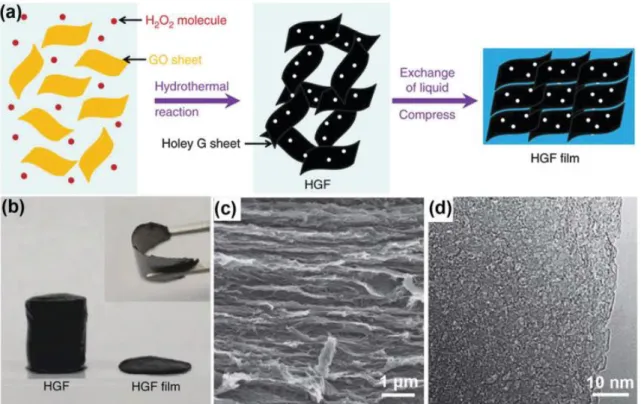
The second chapter presents our initial approach towards synthesizing 3D graphene
monoliths with varied inter-layer separation using short alkyl diamines (hydrazine (C=0), 1,2-diaminoethane (C=2), 1,4-diaminobutane (C=4)) as gel formation agents. Various characterization methods were used to analyze the physicochemical properties of the synthesized monoliths. Among the different monoliths produced, a highly conductive graphene hydrogel was obtained in a single-step reaction using hydrazine hydrate as the gelation agent. The synthesized material, when used as an electrode in 6 M KOH electrolyte, delivered excellent power capability (190 at 0.5 A/g and 123 F/g at 100 A/g) in SCs owing to its high electrical conductivity of 1140 S/m. This initial study using different diamines gave further insights and perspectives into the gel formation ability and reducing nature of various diamines.
The shorter diamines (C=2, 4) used in the previous chapter showed little or no changes in the layered structures of graphene compared to a directly reduced graphene oxide (using hydrazine hydrate). In the third chapter various pillared graphene materials were synthesized using longer diamines (C=5, 6, 8). The syntheses and associated characterization studies of the pillared materials are described in detail. X-ray diffraction patterns confirmed formation of expanded layered graphene structure that have varied inter-layer separation depending on alkyl chain length. A comprehensive study of ion sieving in SCs using various electrolyte ion sizes in an organic electrolyte has shown that ions could access the inter-layer galleries when the naked ion sizes are smaller than the inter-layer gallery height (defined by d-spacing). Electrochemical impedance spectroscopic (EIS) analyses of the pillared materials under positive and negative electrode polarization are presented in the fourth chapter. Extremely
5
impeded ion transport dynamics were observed in the pillared graphene materials as the large number of pillars in between the layers sterically hinders the ion transport. This study gave important perspectives towards synthesis of pillared materials with favorable ion transport dynamics. Banking on the conclusions from the fourth chapter, fifth chapter presents pillared graphene materials with optimized number of pillars. The optimized materials have accessible surface areas and enhanced ion transport characteristics which resulted in both improved energy and power densities. A systematic lowering of the diamine pillars number of equivalents has improved ion access and transport to the adsorption sites. A 3D assembly (monolith) was also synthesized with low number of diamine pillars along with additional macro porosity. A simple drying procedure of this monolith allowed synthesis of the above material with high density (1.1 g/cm3) which enabled high volumetric capacitances ~200 F/cm3.
The results obtained in all the chapters and the overall thesis work are summarized in the sixth
chapter. The perspectives gained from this thesis work for the field of energy storage and
beyond are also discussed. The seventh chapter describes the materials and methods used for all syntheses and characterizations in this thesis. Extensive details about the SCs electrode fabrication and analysis in two, three-electrode SC devices are also presented. Finally, the electrochemical techniques used in this thesis are described in an annex.
References
(1) Simon, P.; Gogotsi, Y. Materials for Electrochemical Capacitors. Nat. Mater. 2008, 7 (11), 845. (2) Rao, S.; Klimont, Z.; Smith, S. J.; Van Dingenen, R.; Dentener, F.; Bouwman, L.; Riahi, K.; Amann, M.; Bodirsky, B. L.; van Vuuren, D. P.; et al. Future Air Pollution in the Shared Socio-Economic Pathways. Glob. Environ. Change 2017, 42, 346–358.
(3) Armand, M.; Tarascon, J.-M. Building Better Batteries. Nature 2008, 451, 652.
(4) Conway, B. E. Electrochemical Supercapacitors - Scientific Fundamentals and Technological Applications; Springer International Publishing: NewYork, 1999.
(5) Béguin, F.; Presser, V.; Balducci, A.; Frackowiak, E. Carbons and Electrolytes for Advanced Supercapacitors. Adv. Mater. 2014, 26 (14), 2219–2251.
(6) Raccichini, R.; Varzi, A.; Passerini, S.; Scrosati, B. The Role of Graphene for Electrochemical Energy Storage. Nat. Mater. 2015, 14 (3), 271.
(7) Stoller, M. D.; Park, S.; Zhu, Y.; An, J.; Ruoff, R. S. Graphene-Based Ultracapacitors. Nano Lett. 2008, 8 (10), 3498–3502.
(8) Li, C.; Shi, G. Functional Gels Based on Chemically Modified Graphenes. Adv. Mater. 2014, 26 (24), 3992–4012.
8
CHAPTER I:
Bibliography
10
Chapter I. Bibliography
1. Supercapacitors
1.1 Interest in Supercapacitors
Climate change and depletion of fossil fuels are among the pressing challenges that require urgent and sustainable solutions. Release of greenhouse gasses such as CO2 and CH4 from using fossil fuels for electricity production and vehicular applications threaten to increase the global temperatures, rise the sea levels and cause extreme weather patterns.1,2 Additionally, burning of fossil fuels also produces large amounts of toxic SOx and NOx gases leading to significant air pollution. Hence, scientists and policy makers are working extensively towards developing clean and sustainable energy solutions. Much effort has been put into studying renewable energy sources such as wind or solar to produce electricity for various applications. However, the intermittent nature of these resources requires intermediate energy storage systems that could store energy when available and deliver when required. Electrochemical energy storage systems offer great potential with their ability to store and deliver electrical energy with minimum losses to conversion.3,4
Figure I-1 Specific power versus specific energy plot, known as Ragone plot, for various electrochemical energy storage devices. Times shown are the time constants obtained by dividing the energy density by power density.2
11
Ragone plot, a plot of specific energy densities vs specific power densities, is commonly used to evaluate the performances of various types of energy storage systems.3 Specific energy quantifies the amount of energy stored in the device whereas specific power evaluates the rate at which the energy could be delivered. Three main types of energy storage devices i.e., batteries, electrochemical capacitors (commonly known as supercapacitors (SCs)) and capacitors are shown with their respective specific power and energy densities (Figure I-1).5 Capacitors store energy through charge separation on two metallic surfaces placed in a dielectric medium and offer the highest power densities but have the lowest energy densities.6 These specific properties of capacitors enabled their extensive application in electrical circuits. Batteries offer highest energy densities and have facilitated the exponential growth of portable electronics from the early 1990s to the present day.4 However, the kinetics of the faradaic reactions in batteries limit faster delivery/uptake of the energy and result in lower power densities. The next generation of portable electronics and development of electric vehicles requires devices that could offer both high energy and power densities.3
From the Ragone plot, SCs could be seen as intermediate between batteries and conventional capacitors. SCs store energy through reversible electrostatic adsorption of electrolytic ions on the charged electrode surfaces.6 When a voltage is applied across the electrodes in SCs, the electrolytic ions of the opposite charge accumulate on the surface of each electrode. Energy is stored through charge separation between an electrode charge and the layer of electro-adsorbed ions. The non-faradaic nature of this charge storage enables rapid storage/delivery of the charge to/from the electrode-electrolyte interface and results in high power capabilities of ~ 15 kW/kg in SCs.3 Additionally, this surface charge storage mechanism lets SCs sustain few millions of charge-discharge cycles with nominal losses in performances. However, as an undesired consequence, the non-faradaic charge storage also results in typically low energy densities of ~ 6 Wh/kg in SCs.3 Batteries, on the other hand, store energy through reversible redox reactions in the electrodes and have high energy densities of ~ 200 Wh/kg but have low energy densities of 1 kW/kg.4 The insertion or conversion mechanism associated with the faradaic charge storage process in the electrodes lead to expansion/degradation/pulverization of the electrode materials and result in limited cycling ability of few hundred cycles. Therefore, SCs can been seen as perfectly complementary devices to batteries in applications that require both high power and energy.7 Table I-1
12
summarizes capacitors, rechargeable batteries and SCs with respect to their performance characteristics.
Characteristics Capacitors Supercapacitors (SCs)
Rechargeable Batteries
Storage Mechanism Electrostatic Electrostatic Chemical
E (Wh/kg) < 0.1 1 - 10 20 - 200
P (kW/kg) >> 10 0.5 - 10 1 - 2
Cycle life (cycles) >> 106 > 106 ~ 1000
Charge-discharge time 10-6 - 10-3 s 10-3 – 1 s 1 – 10 h
Efficiency (fraction) ~ 1.00 0.85 - 0.95 0.70 - 0.85 Operating voltage (Vmax) 6 – 800 V 2.3 - 2.8 V 1.2 – 4.2 V
Vmax determined by Dielectric thickness
Electrode/electrolyte stability
Thermodynamics of the reactions
Self-discharge Low Moderate Low
Operating Temperature -20 to +100oC -40 to +85oC -20 to +65oC
Examples Al, Ta oxide Activated Carbons in TEABF4/AN
Pb Acid, Li-ion, Ni-Cd and Ni-MH
13
1.2 Basics of Supercapacitors
Brief History
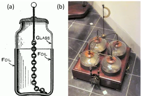
The first capacitor, named as ‘’Leyden jar’’ after the University of Leiden, was independently invented by Edward von Kleist and Pieter van Musschenbroek around 1745.6 This rudimentary capacitor design involved charge storage on tin foils coated on the inner and outer walls of a glass jar filled with water. The inner tin foil in the jar is charged by an electrostatic generator by using a metallic rod/chain as the electrode contact (Figure I-2). Experimental studies on these jars by Benjamin Franklin led to conclusion that the charge is stored in the glass and not in the water. The mechanism of the electrical charge storage in capacitors was then studied and the first model of double layer capacitor was proposed by von Helmholtz in 1853.8 Later in 1950s, General Electric and its engineer H. Becker used activated carbons with high specific surface area (SSA) as electrodes and developed a ‘’low voltage electrolytic capacitor with porous carbon electrodes’’.9
In 1969, the SOHIO corporation patented and produced a double-layer capacitor porous carbon-paste electrode in sulfuric acid electrolyte separated by ion-permeable separator.10,11 However, SOHIO did not commercialize the cells and licensed the technology to NEC (Japan). In 1971, NEC marketed the first supercapacitors in to provide backup power for computer memory.12 Later Panasonic marketed its Goldcaps brand, which became a successful energy source for memory backup applications.13 The first generation of SCs had relatively high internal resistance that limited the discharge current and hence were used for low current
(a)
(b)
Figure I-2 Construction of the Leyden jar; (a) glass jar filled with water and coated with Tin on its interior and exterior surfaces. (b) A battery of four Leyden jars.6
14
applications. The first SC with low internal resistance was developed by PRI and were branded as PRI Ultracapacitor. In 1992, Maxwell laboratories took over PRI technology and named the devices as Boost Caps to signal their power performance.14 Currently, SCs are widely used in various high power applications (see section 1.3). The commercial SCs use porous activated carbons as electrodes and solution of an organic salt dissolved in acetonitrile or propylene carbonate as electrolytes.
Types of Supercapacitors
SCs are largely classified into three different types depending on the charge storage mechanism at the electrode-electrolyte interface. (i) Electric double layer capacitors (EDLCs) are the pure form of SCs, which store energy in electric double layers formed at the electrode-electrolyte interface.6 During charging and discharging of an EDLC no charge transfer occurs across the electrode-electrolyte interface. EDLCs are the most commonly available SCs and use activated carbons with high SSAs as electrode materials (Figure I-3a&c).15–17 (ii) Another group of SCs is pseudo-capacitors that use electrode materials, which undergo fast redox reactions at the surfaces. This faradaic charge storage, called pseudo-capacitance, lead to much greater charge storage compared to EDLCs. Metal oxides such as RuO2 and Fe3O4 and electronically conducting polymers are examples of such redox materials (Figure I-3 b&d).18,19 Pseudo-capacitors differ from batteries with their fast sequence of reversible processes and electron transfer with minimum structural phase changes at the electrodes.
Pseudo-(a) (b)
(c) (d)
Figure I-3 Double-layer capacitance at electrodes comprising a) carbon particles or (b) porous carbon. The double layer shown here arises from adsorption of negative ions from the electrolyte on the positively charged electrode. Pseudo-capacitive mechanisms include (c) redox pseudo-capacitance, as occurs in hydrous RuO2, and (d) intercalation pseudo-capacitance, where Li+ ions are inserted into the host material.
15
capacitors could also have a minor EDLC component through ion sorption on surfaces and EDLCs could have pseudocapacitance contribution through reversible reaction of the surface functional groups in specific electrolytes. (iii) Hybrid capacitors were proposed in the recent years as a combination of a capacitive or pseudo-capacitive electrode with a battery electrode. This type of devices is expected to benefit from high power and high energy properties of capacitor and batteries. This thesis work focuses on the first type of SCs (EDLCs) using carbon-based materials in which charge is stored in electrical double layers.
Applications of Supercapacitors
The range of commercial applications of SCs is expanding and novel materials are being constantly developed and tested as potential electrodes. SCs mainly find applications in systems that require high power input for a short time (low energy) owing to their characteristics described earlier. SCs are used in hybrid electric, electric vehicles, trams and buses as reliable high-power sources under various climate conditions as viable competitors to high-power Li-ion batteries. SCs provide enhanced power during acceleration, capture breaking energy and offer low maintenance operation costs in the long term. Additionally, the growing popularity of the automatic start-stop technology further expands the need of SCs
Figure I-4 Examples of SC applications in (a) electric bus (reproduced from Chinabuses.com), (b) forklift (reproduced from Still, Germany), (c) off-shore wind farms (reproduced from Gottwald, Germany), (d, e) industrial cranes and (f) electric ferries (reproduced from STX, South Korea).
16
with high-power capabilities. SC powered buses capable of charging at the regular stops are gaining popularity in China and Europe (Figure I-4).
SCs are most commonly used in industrial equipment including hybrid forklifts and hybrid cranes. The high power and good low operating temperature of SCs make them very viable for operation in forklifts that function in refrigerated warehouses. SCs are also viable for all-electric short distance ferries (5-20 min) or well-equipped military ships that have strong need for mobility and reliability. Uninterruptable power is critical to key applications where the cost of interruptions could be life/health threatening (ex. Hospitals, data centers, communication facilities etc.). Backup standby generators require few seconds to minutes to plug in. SCs could be used as backup power sources in such key applications. The backup power from SCs is also used to power wind turbine control systems that need to maximize the energy harvesting by controlling motor speed. SCs provide reliable supply in wind farms that are often in remote locations and have minimum maintenance costs.
17
1.3 Fundamentals of Electrical Double Layer Capacitors
In a conventional capacitor, two conductive metallic plates are separated by dielectric media such as glass, ceramics, paper or mica (Scheme I-1). Opposite charges are stored on the two metal plates (separated by a given distance d) by applying an external bias voltage. These opposite charges on the metallic plates are maintained by the insulating dielectric material and an electric field is thus developed between the two oppositely charged plates. The amount of charges stored (Q in Coulomb) is determined by the capacitance (C in Farads) and the voltage difference (V in volt) across the capacitor as defined in Equation I-1 .The ability of a capacitor to store energy in an electric field is quantified as ‘’capacitance’’. Specifically, capacitance is described as the derivate of charge stored to the corresponding change in its electric potential. One Farad of capacitor signifies one Coulomb at a potential difference of one V. Capacitance depends on the geometry of the electrodes, permittivity of the dielectric material and the separation between the charged plates (Equation I-2). εo and ε are the permittivity of a vacuum (8.85 * 10-12 F/m) and electrolyte dielectric constants respectively. A is the area of the plates and d is the distance of separation between the two plates.
Q = C ⋅ V
C =
εo ⋅ ε ⋅ A
d
Equation I-1
Equation I-2 Scheme I-1 Schematic representation of a parallel plate capacitor
18
Electric Double Layer Theory
The basic charge storage mechanisms in EDLCs is similar to a parallel plate capacitor where the conductive plates are replaced with different active materials (ex. Porous carbons) and a polymeric separator immersed in electrolyte is used instead of the dielectric material. Electronic charges accumulate at positive and negative electrode surfaces when an external bias is applied. The cations and anions in the electrolyte move towards the oppositely charged electrode surfaces due to electrostatic attraction and accumulate as layers. The charge separation at the electrode-electrolyte interfaces is referred to as ‘’electric double layer’’ (EDL) giving rise to the term electric double layer capacitor. The concept of EDL was first described and modeled by von Helmholtz in 1853 and this model states that two layers of opposite charges form at the electrode-electrolyte interface and are separated by an atomic distance d (Figure I-5a).8 The potential near the electrode decreases when the distance (m) between the ions and the electrode increases. The Helmholtz double-layer (DL) could be regarded as an electric capacitor of capacitance CH (Equation I-3) with an electrode surface area S (m2). d is the effective thickness of the DL and is often approximated as the Debye length. Considering the very large SSA of the porous carbon electrodes and a Debye length < 1 nm, the resulting capacitance of DL’s will be much higher than parallel plate capacitors.
CH =ε0 . εr . S d
The Helmholtz model does not consider several factors such as diffusion of ions in the solution and the interaction between dipole moment of the solvent and the electrode. Gouy in 1910 and Chapman in 1913 proposed a diffuse model of the EDL in which ions in the electrolyte (both cations and anions) are considered as both mobile and under influence of the electrostatic forces leading to formation of a diffuse layer (Figure I-5b).20 The potential decreases exponentially across the diffuse layer into the bulk of the electrolyte. However, the Gouy-Chapman model overestimates the EDL capacitance as it treats ions as point charges. In 1924, Stern combined the Helmholtz model with the Gouy-Chapman model to explicitly recognize two regions of ion distribution; the inner region as a compact layer or Stern layer and the outer diffuse layer (Figure I-5c).21 The inner compact layer consists of strongly adsorbed ions which are often solvated. Additionally, the diffuse layer consists specifically of
19
adsorbed ions and non-specifically adsorbed counter ions at both positive and negative electrode surfaces. These two layers are equivalent to two capacitors in series, CH (Helmholtz layer) and CD (diffusion layer) and the total capacitance of the electrode is given by CDL (Equation I-4). 1 CDL = 1 CH + 1 CD
A traditional EDLC consists of two porous carbon electrodes in direct contact with the current collector and separated by a polymer film impregnated with an electrolyte solution (Scheme I-2). When a potential difference is applied between the two electrodes, electrons at the
Equation I-4
Figure I-5.(a) Helmholtz, (b) Gouy-Chapman, and (c) Stern model of the electrical double-layer formed at a positively charged electrode in an aqueous electrolyte. The electrical potential, φ, decreases when transitioning from the electrode, φe, to the bulk electrolyte infinite away from the electrode surface, φs. The
Stern plane marks the distance of closest approach of the ions to the charged surface. Note the absence of charges/ions in the Stern layer. The diffuse layer starts in the range of 10 – 100 nm from the electrode surface.17
20
negatively polarized electrode are balanced by an equal number of positive cations at the electrode/electrolyte interface, while the holes stored at the positively polarized electrode are electrically balanced by anions. Hence, a SC consisting of two electrodes is equivalent to two capacitors in series with additional solution resistance and the resulting capacitance (C) can then be expressed according to Equation I-5. C+, C- and C are capacitances of the positive electrode, negative electrode and the whole device respectively.
1 C= 1 C++ 1 C−
In order to compare the performances of various electrode materials, it has become a common practice in the literature to provide specific gravimetric capacitances of material relating to the capacitance of a single electrode (CSP). Specific volumetric capacitances can also be used as a measure of the compactness of the materials. In case of a symmetric system with equal electrode masses, sizes and thicknesses, CSP is given by Equation I-6, where mAM is the total mass of the active materials in both electrodes.
The specific energy stored (Wh/kg) and the deliverable specific power (W/Kg) of a SC are represented by Equation I-7 & Equation I-8 Vmax is the maximum electrochemical stable window, ESR is the equivalent series resistance and m is the total mass of the SC. The ESR of EDLC corresponds to the sum of ionic resistances, electronic resistances and the interface resistance between electrodes and current collectors.
Equation I-5
21 CSP = 4 . C mAM E= C . Vmax 2 2 . m . 3600 P = Vmax 2 4 . ESR . m Equation I-6 Equation I-7 Equation I-8
22
2. Cell Design Characteristics for SCs
SCs offer great power performance for various specific applications but suffer from low energy values for their application in large-scale applications like rechargeable batteries. Thus, the main challenge in the field of SCs has been to improve the energy densities and still maintain their high-power performances. Extensive research has been devoted towards finding new electrolytes and electrode materials that could offer such ideal performances.17,22,23 The core strategies in this research arise directly from the specific energy and power equations described earlier.
Energy and power densities of SCs can be enhanced significantly by increasing the operational voltage window (Vmax) of the SC as they depend on Vmax through a square relationship (Equation I-7& Equation I-8). The maximum operational voltage of a SC is generally determined by the nature of the electrolyte. Electrolytes based on aqueous, organic and ionic liquid (IL) media all have different operational windows determined by the electrochemical stability of the solvents.24 Specific electrolytic ions dissolved in the above solvents and the interactions with electrode surfaces could also determine the maximum possible operational window. While enhanced Vmax is a positive attribute of a SC, the equivalent circuit resistance (ESR) is also an important parameter for determining the power of a SC. ESR is the sum of various types of resistances including the intrinsic resistance of the electrode material, electrolyte solution, mass transfer resistance of the ions and the contact resistance between current collector and the electrode material.24 Among the various resistances, the resistance of the bulk electrolyte solution and the electrolyte inside the electrode pores dominate the overall ESR. Unfortunately, often there is a trade-off between the Vmax and the ESR of a system. Aqueous electrolytes such as H2SO4 or KOH have high ionic conductivities but the operational voltage window is low. In contrast, organic and IL electrolytes offer high Vmax but their ionic conductivities are at least one order lower than aqueous electrolytes.
The energy densities of pure double layer capacitors could be improved by increasing the surface area of the electrode that is accessible for electrochemical ion sorption (Equation I-2).23,25 Thus, achieving higher electrochemically active surface area has been a well-defined and straightforward challenge. It was commonly assumed that increasing the overall specific surface area (SSA) of an electrode material would lead to enhanced electrochemical active
23
surface area (A).17,26 Hence, over the past two decades, several materials with high surface areas have been analyzed for application as electrode materials in SCs.22 In the early 2000s, fundamental understanding of ion sorption on carbons surfaces has revealed the importance of the size, shape and distribution of pores in a particular material.27–29
The energy densities of SCs could also be improved by using electrodes or electrolytes that offer additional attributes. The charge storage capability of an electrode material could be enhanced through addition of redox processes,6 decreasing the distance (d) between ions and the carbon electrode surface and by modifying the permittivity of the EDL, which is mainly governed by the electrolyte.30 Addition of redox reaction processes to an electrode material (pseudo-capacitance) is known to enhance the capacitance by nearly 10 fold as compared to double layer charge storage (ex. RuO2). However, such an addition also results in problems that rechargeable batteries typically face: poor cycle life and power performances.3 Nevertheless, pseudo-capacitance offer great potential as an intermediate between batteries and pure capacitors with mixed attributes.
Specific attributes and types of electrolytes and electrode materials suitable for SC applications are detailed briefly in the following section.
24
2.1 Electrolytes
An electrolyte solution typically consists of a salt dissolved in a solvent. Broadly, the ions in the electrolyte solution provide charge compensation to the electronic charges accumulated on each electrode in a SC. As the two electrodes are oppositely charged, electrolytic ions of the opposite charges adsorb on the electrode surfaces to form electrical double layers. Hence, an electrolyte provides an ionic conducting media and insulating to flow of electrical charges. Electrolytes such as those made with ionic liquids and solid-state polymers could differ from the traditional definition of salt + solvent (discussed in detail below). As electrolyte is a key component of the double layer charge storage process, it has to meet various key requirements to be considered as an ideal electrolyte.30,31 An ideal electrolyte has: (a) a wide voltage window of stability; (b) a high ionic conductivity; (c) a wide operating temperature range; (d) low volatility and flammability; (e) chemical and electrochemical inertness to SC components; (f) low viscosity for low ESR; (g) environmentally friendly and (h) low synthesis costs. As it is difficult for an electrolyte to meet all these requirements, various types of electrolytes are developed and reported in the literature, each with respective merits and demerits.30 The reported electrolytes are broadly classified into three classes based on the solvent present (Figure I-6).
25
Aqueous Electrolytes
Aqueous electrolytes are cost effective, safe, could be handled easily and greatly simplify the overall SC fabrication and assembly process. Comparatively, organic and IL electrolytes require complicated purification procedures and need a moisture-controlled atmosphere. Another unique advantage of aqueous electrolytes is their high ionic conductivities and correspondingly low ESR values, which lead to better power capabilities. For example, 1 M H2SO4 has about 0.8 S/cm conductivity at 25oC whereas that of 6 M KOH 0.6 S/cm at the same temperature. The major disadvantages of aqueous electrolytes are the limited maximum operating voltage window and operational temperature range. The voltage window of aqueous electrolytes is restricted by the decomposition of water. The hydrogen evolution generally limits negative potential at around 0 V vs. SHE and the oxygen evolution occur at 1.23 V, thus resulting SC has a cell voltage of about 1.23 V. To avoid gas evolution, the cell voltage of aqueous SCs, is commonly restricted to 1 V. Additionally, the temperature range of aqueous SCs is restricted by the boiling and freezing point of the electrolyte.
In general, aqueous electrolytes are grouped into acidic, alkaline and neutral solutions in which H2SO4, KOH and Na2SO4 are representatives and are the most frequently used electrolytes. The three types of electrolytes benefit from specific attributes. (i) Acidic and alkaline electrolytes support various pseudo-capacitive mechanisms and aid the overall charge storage.32,33 (ii) Neutral electrolytes have lower H+ and OH- concentration compared to acidic and alkaline electrolytes, and enable higher stable voltage windows up to 2.2 V.34 Specific demerits of the electrolytes include corrosive nature of acidic solutions towards current collectors and relatively low conductivities of neutral solution due to solubility issues. Despite all the merits and demerits, the low operating voltage windows of aqueous electrolytes has been the major hurdle towards commercial applications.
Organic Electrolytes
Although extensive academic studies have been focused on using aqueous electrolytes in SCs, organic electrolytes currently dominate the commercial applications owing to their high operational voltage window (~ 2.8 V).30,31 Most organic electrolyte-based SCs use acetonitrile (AN) solvent while others employ propylene carbonate solvent (PC).35 The increased voltage window provide significant improvements in energy and power densities. Additionally, the specific salts and solvents used in organic electrolytes enable desired performances in a wide
26
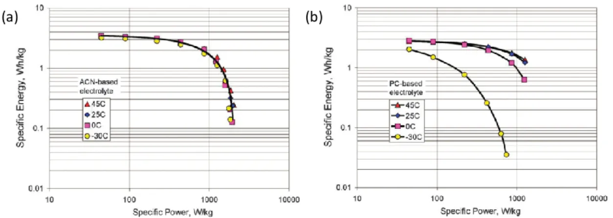
range of temperatures. Typical organic electrolytes for commercial SCs use conductive salts (ex. Tetraethylammonium tetrafluoroborate salt (TEABF4)) dissolved in AN or PC,36 it has been reported that the specific capacitance of a SC in 1 M TEABF4/AN did not have any obvious changes when the temperature is decreased from 45 to -30oC (Figure I-7a). 37
However, the high operational cell voltages lead to concerns of aging and degradation of cell performances.38,39 Wide cell voltage could cause accelerated oxidation of electrode materials
and intercalation of electrolytic ions into layered materials. Both such cases lead to irreversible changes in the electrode materials and cause performance degradation with time.36 Other important issues regarding organic electrolytes include higher costs, lower specific capacitances and safety concerns related to flammability, volatility and toxicity.40–44 Another drawback of organic electrolytes compared to aqueous electrolytes is their low ionic conductivities.36 For example, the ionic conductivity of the most commonly used 1 M TEABF4/AN is 0.06 S/cm, which is significantly lower than that of 1 M H2SO4 at 25oC (0.8 S/cm). Similar to aqueous electrolytes, the nature of salts and solvents in the electrolyte has a profound impact on the performances of SCs and needs optimization of various parameters. Specific tests of SCs performed by Kotz et al. gave very different responses when 1 M TEABF4/PC was used instead of 1 M TEABF4/AN.42 The conducting salts in the electrolyte also have a profound impact on the Vmax, thermal stability and the overall capacitances of SCs. Careful consideration should be given on the solubility, stability and conductivity of the individual salts. Figure I-8 shows an example demonstrating that there are optimum ion
(a) (b)
27
concentration values for achieving maximum ionic conductivities in each electrolyte. TEABF4 has limited solubility (up to 1 M) in PC whereas other salts show higher solubility above 2 M.36
Ionic Liquid based electrolytes
Ionic liquids (IL) are generally defined as salts that are solely composed of ions with melting points below 100oC.45 An IL generally has a large asymmetric organic cation and an inorganic or an organic anion, and this special combination of certain cations and anions contributes to a low vapor pressure.46 The intrinsic energetics involved in the interactions between the anions and cations are typically measured by the surface tension of the ILs. ILs offer several potential advantages including high thermal, chemical and electrochemical stability, negligible volatility and non-flammability (certain ILs).47 These positive attributes render ILs as safe for high-temperature applications (80oC or more). Moreover, the physical and chemical properties of ILs are highly tunable and offer excellent opportunity for optimization.48 The major advantage of the IL electrolytes over organic and aqueous electrolytes is their high Vmax values of higher than 3 V.
Unfortunately, there are several main drawbacks with most ILs, such as high viscosity, low ionic conductivity and high costs, which can limit their practical use in SCs. Even for [EMIM][BF4] electrolytes, which has relatively high ionic conductivity among common ILs, its conductivity (0.014 S/cm) is still much lower than that of organic or aqueous electrolytes. Both low conductivity and high viscosity of ILs can significantly increase ESR values and limit power performances in SCs. Additionally, specific capacitances of IL based SCs are significantly low, probably due to the high viscosities.49
Figure I-8 Ionic conductivity as a function of quaternary ammonium tetrafluoroborate salt concentration in PC solvent.36
28
Solid or Quasi Solid-State Electrolytes
Solid state electrolytes can serve as both ion conducting media and electrode separator. The rapid growing demand of power for portable electronics, printable electronics and flexible devices is the major driving force behind application of these electrolytes in SCs. The major advantage of such electrolytes are the simplification fabrication and packaging of leakage proof SC devices.50–52 Currently, solid-state electrolytes are mainly based on various polymers and are classified as solid polymer, polyelectrolytes and gel polymer electrolytes. A solid polymer electrolyte is made of a polymer and a salt without any solvent. A gel polymer electrolyte consists in a polymer host (ex. Polyvinyl alcohol) and a liquid electrolyte (ex. H2SO4) and have the highest ionic conductivity among the three types of electrolytes.50 Polyelectrolytes conduct ions through charged polymer chains.
Gel Polymer Electrolytes (GPEs) are currently the most extensively studied electrolytes for solid-state ES devices and they consist of a polymer matrix and an aqueous salt solution or an organic salt solution or an ionic liquid as the liquid electrolyte in the polymer host. Depending on the electrolyte constituent, the GPEs are called as Hydrogels, Organogels and Ionogels. Examples of GPEs include H2SO4 or KOH Poly(vinyl alcohol) as hydrogel, LiClO4/DMF in Polyvinylpyrrolidone (PVP) as organogel and [BMIM][Cl] ionic liquid in PVP as ionogels Owing to the individual characteristics of the constituent liquid electrolyte (see previous sections), GPEs differ in properties such as thermal behavior, voltage window and environmental stability.
The main drawback of these electrolytes is their poor mechanical strength and narrow operational temperature range. Globally, solid electrolytes also suffer from limited contact surface area with electrode materials (especially for nanoporous materials), and lead to low specific capacitances and high ESR values.51
With the merits and demerits of each class of electrolytes explained above, a choice of the electrolyte for a SC system should be made by considering the nature of charge storage (EDLC/pseudo-capacitance) and operational conditions (temperature) and requirements (energy and power) of a SC.
29
2.2 Electrode Materials
As described in the previous section, energy densities of SCs could be increased by choosing materials with high electrochemically active surface area as electrodes. Additionally, high electrical conductivity of the electrode materials is essential to maintain low ESR and achieve high power performances. Hence, the choice of electrode materials for supercapacitors requires high specific surface area (SSA) and good electrical conductivity (~ 1 S/cm).
Carbons are one among the most abundantly available and structurally diverse materials, making them the preferred choice of electrode materials in SCs.53 Abundantly available organic materials, such as food waste, are particularly attractive as natural sources for the production of carbon materials. Carbon materials also have desired attributes such as low cost, variety of form (powders, fibers, aerogels, and monoliths), ease of process ability, relatively inert electrochemistry and controllable porosity. Activated carbons (ACs) are the most commonly used porous carbons used in the commercial SCs owing to their high specific surface areas (SSA) and costs.54,55
The specific surface area of an electrode material is an important parameter for ion sorption but other aspects such as pore sizes, shapes and their connectivity are also crucial for enhanced electrochemically active area.56 The International Union of Pure and Applied Chemistry (IUPAC) defines pores according to their sizes as micropores (< 2 nm), mesopores (2-50 nm) and macropores (> 50 nm).57 The broad consensus on the role of different pores in SCs is that the micropores provide ion sorption sites, mesopores act as channels for electrolytes ions to the sites and the macropores act as electrolyte buffers. Thus, an inter play between different types of pores is crucial.58
30
Different forms of carbons materials are known to offer varied porosity characteristics (pore shapes, size distributions, volume), diverse physical and chemical properties (Table 1.2). Onion-like carbons, carbon nanotubes (CNTs), graphene, ACs, Carbide-derived carbons (CDCs) and templated carbons are carbons with different dimensional arrangement in space that have been investigated for next generation SCs with potentially high energy and power densities. In this section, different carbon materials are briefly summarized and discussed with respect to their synthesis methods, characteristic structures and electrochemical performances in SCs.
Onion-Like Carbon
Onion-Like Carbon (OLC), also called as carbon onions or multi-walled fullerenes, consist concentric spherical graphitic sheets.59,60 It can be mass produced either by arc-discharge or by annealing diamond nanoparticles in an inert atmosphere at temperatures above 1200oC (Figure I-9a & b). OLC have moderately high BET SSA of 400-600 m2/g with relatively low cost and high conductivity for applications in SCs (~ 4 S/cm).61 OLCs have open surface structure and are free of micropores with particle size ranges from 5 to 15 nm.62 Since all the surface area is fully ion accessible without ion transport limitation like in a microporous network, OLCs presents high power capability (Figure I-9c). Micro-supercapacitors based on these OLCs showed impressive rate capability (up to 200 V/s) and relaxation time constant (26 ms). Yet the low SSA of this material gives a poor energy performance and low capacitance (~ 30 F/g) in 1.5 M TEABF4/AN electrolyte and make them suitable for micro-supercapacitor applications with low energy demands.63
(a)
(b)
(c)
Figure I-9 TEM images of OLC produced by (a) arc discharge method60 and (b) annealing nano-diamond
31
Carbon Nanotubes
Carbon nanotubes are one dimensional carbon materials with cylindrical structure commonly grown via catalyst-assisted chemical vapor deposition (CVD) techniques using hydrocarbon-based precursors such as methane, acetylene etc.64 CNTs consist either of one rolled-up graphene (single-walled CNT) or of several co-axial ones (multi-walled CNT) (Figure I-10). CNTs are characterized by their superior electrical conductivity, excellent thermal and mechanical stability and are suitable for application in SCs. Current trend is to grow CNTs vertically on conductive substrate to allow a direct contact between the current collector and the CNTs.65 Such assemblies facilitate low contact resistances (correspondingly low ESR) and easier ion accessibility form bulk electrolyte to the CNT surfaces. Similar to OLCs, CNTs have an exohedral surface with moderate SSA 120-500 m2/g (single wall CNTs have up to 1000 m2/g) and result in moderate gravimetric capacitances of 50-90 F/g.64 The low CNT material density and moderate SSAs result in low volumetric capacitance and energy densities of SCs. Nevertheless, the high electrical conductivity and open porosity of CNTs can allow fast ion transport and power performances in SCs. Research has been undertaken to improve the energy density of CNTs by increasing their specific surface area via chemical activation (KOH activation). However, a proper balance between porosity and conductivity must be achieved in order to have both high capacitance and good rate performance. Another way to improve energy densities of CNTs is by decorating them with a thin layer of pseudo-capacitive materials on the surface as the tubular structures of CNTs also make them a good host for additional active materials.66 In spite of having excellent properties, the limited surface area, high production costs and purity issues still hinder commercial application of CNTs. Additionally, the health and safety aspects of CNT fibers (probable carcinogenic agents) hinder their use in SCs.
(a) (b) (c)
32
Various 3-D Carbons
Activated Carbons (3-D) Structure
ACs are non- graphitized forms of carbons that are unable to restack even after treatment at 3000oC.3 The textural entanglement of ACs is explained by presence of structural fragments resembling fullerenes with pentagons and non-hexagonal rings, giving rise to curvatures.22 ACs are the most widely used electrode materials in SCs due to their large surface area, relatively good electrical properties and moderate costs of synthesis.53 ACs are generally produced from thermal and/or chemical activation of various types of carbonaceous materials (e.g. wood, coal, nutshell, etc.).67 Thermal activation usually involves treatment of carbon precursors at high temperature (from 700 to 1200oC) in the presence of oxidizing gases such as steam and CO2. Chemical activation is usually carried out at relatively lower temperatures (from 400 to 700oC) with activating agents like phosphoric acid, potassium hydroxide and sodium hydroxide.68 Depending on the activation methods as well as the carbon precursors used, ACs possessing various physicochemical properties with very high surface areas of 3000 m2/g are produced. The porous morphology of ACs have a broad distribution of micro, meso and macropores.69 Despite their high surface areas, in general, specific capacitance values ranging from 150-300 F/g and up to 150 F/g are observed in aqueous and organic electrolytes respectively.3 It was suggested that for carbons with high SSA, the pore walls might become too thin to provide complete charge screening of the ions in the pores.70
Currently, ACs are applied as electrodes in commercial SCs restricted only to a certain niche markets due to their limited energy storage and rate capabilities.71 The specific surface area is an important parameter for ion sorption but other aspects such as pore sizes, shapes and their connectivity are also crucial for enhanced electrochemically active area.72 Furthermore, excessive activation will lead to larger pore volume and results in the drawbacks of low material density and conductivity.17 In addition, high surface areas may increase the risk of decomposition of the electrolyte at dangling bond positions.73 Therefore, designing ACs to have narrow pore size distribution (accessible to electrolyte ions) with an interconnected pore structure would benefit the energy density of SCs without deteriorating their power density.74
33
Templated Carbons (3-D)
Templating method offers another effective way to produce nanostructured carbons with well controlled narrow pore size distributions, ordered pore structures, large specific surface areas and an interconnected pore network (Figure I-11).75 These unique properties make them suitable for applications in SCs. In general, templated carbons are prepared by infiltration of a carbon precursor into the pores of a template, followed by a carbonization treatment and finally the removal of the template to leave behind a porous carbon structure. Various carbon structures with well-controlled micropores, mesopores and/or macropores produced from different types of template and carbon precursors have been studied for supercapacitor applications.76,77
A functionalized microporous carbon material was obtained by using zeolite Y as a template and the resultant carbon material possessed a high gravimetric capacitance of about 120-340 F/g in aqueous electrolyte and 60-150 F/g in organic electrolytes with good cyclability (over 10000 cycles).78 Compared to ACs with disordered micropores and broad in-pore size distribution, the templated microporous carbons with a narrow pore size distribution, well adapted pore size to the electrolyte ions and the ordered straight pore channels are better for use as high-energy-density electrode materials. Relatively high cost of production of the sacrificial templates is the main drawback of the templated carbons.22 Development of a simple, economical and environmentally benign template route would be advantageous for their future application. Despite the cost, templated carbons are a model class of materials which could provide valuable information about the effect of pore size, pore shape, channel structures and other parameters on the ion diffusion and charge storage in SCs.