# R P 9 6 - 0 5 - 1 4 N o v e m b e r 1 9 9 6
Axiomatic Design of Manufacturing Systems
Prepared by: David S. Cochran and Vicente A. Reynal
Lean Aircraft Initiative
Center for Technology, Policy, and Industrial Development Massachusetts Institute of Technology
Massachusetts Avenue • Room 33-407 Cambridge, MA 02139
The authors acknowledge the financial support for this research made available by the Lean Aircraft Initiative at MIT sponsored jointly by the US Air Force and a consortium of aerospace companies. All facts, statements, opinions, and conclusions expressed herein are solely those of the authors and do not in any way reflect those of the Lean Aircraft Initiative, the US Air Force, the sponsoring companies and organizations (individually or as a group), or MIT. The latter are absolved from any remaining errors or shortcomings for which the authors take full responsibility.
Abstract
This paper introduces the use of axiomatic design in the design of manufacturing systems. The two primary functional requirements of any manufacturing system are developed. These functional requirements are used to analyze the design of four manufacturing systems in terms of system performance. The purpose of this work is to provide a new foundation for describing, determining and rationalizing the design of any new manufacturing system.
Introduction
The motivation for the application of axiomatic design to describe the design of manufacturing systems is threefold. The first reason is that a revolution has occurred in terms of the design and operation of manufacturing systems. This change is marked by many of the methods spawned by the Toyota Production System and subsequently, the characterizations of lean and agile manufacturing. Academia and industry have not defined the fundamental design principles that characterize the changes that have occurred. Industrial and business publications have largely enumerated characteristics of systems. These characterizations are often portrayed by buzz or catch words. To be able to advance manufacturing system design and new manufacturing paradigms, the design principles must be understood.
The second reason is that a methodology must be used to systematically relate the desired design outcomes (known as functional requirements in axiomatic design terminology) to the design principles and design parameters that are used to achieve the desired result. Since systems embody a complex arrangement of physical elements characterized by measurable parameters with corresponding inputs and outputs [Black, 1990] and since large systems must meet the time-variant nature of changing functional requirements, the corresponding design parameters of a system must be adaptable over time [Suh,1995]. The message is the need to be able to systematically propagate the functional requirements of system to the various facets of a system’s design. Specifically, within manufacturing systems we define the interactions that occur within the following facets or levels within a system: production system level, manufacturing system, sub-system or
DAVID S. COCHRAN is a Professor in the Department of Mechanical Engineering at the Massachusetts Institute of Technology (MIT). He is the Director of the Production System Design Laboratory at MIT. His areas of study are the design and control of manufacturing systems.
VICENTE A REYNAL is a Graduate Research Assistant at the Massachusetts Institute of Technology (MIT). He is a candidate for a Master of Science in Mechanical Engineering and a Master of Science in Technology and Policy.
Address reprint request to David S Cochran and/or Vicente A Reynal, 77 Massachusetts Ave., Room 35-229, Cambridge, MA, 02139 USA. Phone: +1 (617) 258 6769; Fax: +1 (617) 253 2123; email: [email protected], [email protected]
cell design level and operation/machine design level. It is critical that the Functional Requirements at one level are propagated to lower levels.
Production System Sub-system or cell design Manufacturing System Operation/ Machine design
Figure 1: Production System Design Hierarchy
The notions of value stream [Womack,1996] and supply chain [Fine,1989] have been used to indicate the need to coordinate between various physical manifestations of a system to create value in the manufacture of products. These terms are characterizations of the interdependent nature of systems. Therefore, a design of a manufacturing system must also recognize the linkage between functional units which supply other functional units of a system. This linkage is indicated by Figure 2.
Input Cell 1
Ouput (from cell1)
Input (to cell 2)
Cell 2 Output
Link 1 Link 2
Figure 2: The Interdependent Nature of Manufacturing Systems
The hierarchy in Figure 1 and the linkage in Figure 2 will provide the design pedagogy to capture system design dependent parameters and time dependent parameters, respectively.
The third reason for applying axiomatic design to the design of manufacturing systems results from the problem that books describing the new/future manufacturing revolution treat the required changes as a set of heuristics to be copied or emulated [Suzaki, 1987]. The truisms of the manufacturing system design in terms of meeting the functional objectives of a system (e.g., what the manufacturing system should do) and the design
parameters (e.g., how the manufacturing system will do it) are not apparent and in many cases not understood.
This paper introduces the use of axiomatic design in the design of manufacturing systems. The two primary functional requirements of any manufacturing system are developed. These functional requirements are used to analyze the design of four manufacturing systems designs in terms of system performance. The purpose of this work is to provide a new foundation for describing, determining and rationalizing the design of any new manufacturing system. This methodology provides a design basis for determining the design of intelligent manufacturing systems and the application of intelligent technologies.
Key Concepts of Axiomatic Design
Axiomatic Design defines design as the creation of synthesized solutions in the form of products, processes or systems that satisfy perceived needs through mapping between Functional Requirements (FRs) and Design Parameters (DPs) [Suh,1990]. The FRs represent the goals of the design or what we want to achieve. FRs are defined in the functional domain in order to satisfy the needs which are defined in the customer domain. The DPs express how to satisfy the FRs. DPs are created in the physical domain to satisfy the FRs. The design domains are shown in Figure 3. The customer domain is where the customer needs reside. These needs must be mapped to the functional domain where the customer needs are translated into a set of FRs, which by definition, are independent. Not only will Functional Requirements be defined for the new design, but also constraints will appear as a result of translating customer wants to FRs. Constraints have to be obeyed during the entire design process. They refer to FRs, as well as to DPs and PVs. This fact is indicated in Figure 3 by placing the constraints above the functional, physical and process domain. The FRs are then mapped to the physical domain and the DPs are mapped to the process domain in terms of process variables (PVs).
Customer Domain Functional Domain Physical Domain Process Domain Functional Requirements Design Parameters Process Variables Customer Wants Constraints • Customer needs • expectations • specifications • bounds • laws •
Figure 3: All Designs can be Represented in Four Domains [Suh,1990]
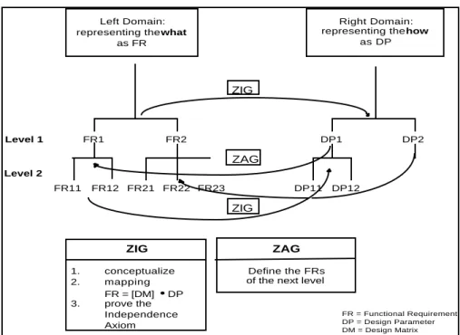
In most design tasks, it is necessary to decompose the problem. Figure 4 indicates hierarchies in the functional, physical and process domains. The authors believe that in the case of a manufacturing system design, the decomposition in the Functional Domain and Physical Domain is most effective. The development of the hierarchy will be done by zigzagging between the domains. The zigzagging takes place between two domains. After defining the FR of the top level, a design concept has to be generated. This results in the mapping process as shown in Figure 4
FR = Functional Requirement DP = Design Parameter DM = Design Matrix
Left Domain: representing the what
as FR
Right Domain: representing the how
as DP Level 1 Level 2 ZAG FR1 FR2 DP1 DP2 FR22 FR23 FR21 FR11 FR12 ZIG 1. conceptualize 2. mapping FR = [DM] • DP 3. prove the Independence Axiom ZAG Define the FRs of the next level
DP11 DP12
ZIG
ZIG
Figure 4: Zigzagging Between the Domains to Developed the Hierarchy
In order for mapping to be satisfied between domains, two axioms must be followed [Suh,1990]:
Axiom 1: The Independence Axiom
Maintain the Independence of the FRs Axiom 2: The Information Axiom
Minimize the Information Content of the design
The mapping between FRs and DPs described mathematically as a vector. The Design Matrix (DM) describes the relationship between FRs and DPs.
{FRs} = [DM]{DPs} (1)
An element in the design matrix DMij is given by
DM FR DP ij i j = ∂ ∂ (2)
which is a constant in linear design. In order to satisfy the Independence Axiom, [DM] must be a diagonal or triangular matrix. The design with a diagonal matrix is called an uncoupled design and a design with a triangular matrix is called a decoupled design. Decoupled designs satisfy the Independence Axiom provided that the DPs are implemented or set in a specific sequence. All other designs are coupled.
The second axiom (information axiom) is defined in terms of the probability of successfully achieving FRs or DPs. The information is defined as:
I = i = 1 n log 2 Σ 1 p i (3)
where pi is the probability of DPj satisfying FRi and log is either the logarithm of base 2
(with the units in bits) or the natural logarithm (with the units in nats). Since there are n FRs the total information content is the sum of the probabilities. The Information Axiom states that the design with the smallest i is the best design since it requires the least amount of information to achieve the functional requirements of the design.
The Design of Manufacturing Systems
Each element of the production system chain, whether it is a plant, a cell or a machine may be represented by Figure 5
Figure 5: Production System Chain
Various manufacturing systems may be represented as elements in the production system chain. With the use of axiomatic design, the important functional requirements of a manufacturing system can be determined. An extremely critical functional requirement of a manufacturing system design is to synchronize the cycle time of each element (i) in the production system chain with the demand rate of element i+1. This notion is articulated in many current industrial settings by the Takt Time calculation. Takt time is the means to synchronize production with customer demand. Two steps are required to obtained the takt time of the system or sub-system:
1. Average Daily Demand =
2. Takt Time =
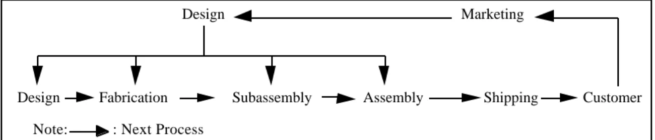
In 1950, W. Edwards Deming focused the attention of Japanese Manufacturing to treat each downstream process (i+1) as the customer of process (i) as seen in Figure 6. Takt time resulted as the means of synchronizing the production rate with the demand.
Design
Design Fabrication Subassembly Assembly Shipping Customer Marketing
Figure 6: Downstream Process as Customer in Production Chain (This concept was originally presented by Dr. Edward Deming at a top management seminar at Hakone, Japan in 1950) [Suzaki, 1987]
The word “takt” comes from the german word “to pace”, meaning to control the rate. Therefore, the first functional requirement may be stated as:
FR1: Synchronize Cycle Time of each Element (i) with the demand rate of Element (i+1)
Synchronizing the cycle time for each element in the production system chain minimizes the variation between each element and provides predictability in terms of production
Average Monthly Demand # of days in a month Available Daily Time
Average Daily Demand
Note: : Next Process
output. The goal is to convert the sources that cause a stochastic output to a design which provides a deterministic output. The design parameters obtained by mapping the functional requirements of the system, provide the means of making the conversion from a stochastic system to a deterministic system.
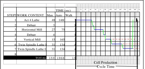
A synchronous and predictable output cannot be achieved unless the work of the machine and operator combined is standardized and predictable. Figure 7 indicates a procedure to standardize the man and machine’s work and the man-machine work interface.
The design parameter that will satisfy FR1 is the following :
DP1: Standardized Work of all Work Elements (i ±∞)
TIME (sec) STEPSWORK CONTENT Man. Auto Walk
1 Act 4 Lathe 48 1460 3
2 Deburr 3 1
3 Horizontal Mill 27 75 3
4 Deburr 4 1
5 Vertical Mill 15 165 3
6 Twin Spindle Lathe I 31 134 4 7 Twin Spindle Lathe II 31 134 4 8
TOTAL 159 1968 19
15 30 45 60 75 90 105 120 135 150 165 180 195
Figure 7: Example of a Standardized Work Routine Sheet
Decomposition of FR1
Zigzagging between domains leads to the definition of two subordinate functional requirements to FR1:
FR11: Eliminate Variation due to Manufacturing Operations (e.g. fabrication equipment)
FR12: Eliminate Variation due to Cell Control Functions
(e.g. human operators, robots, cell control computer, material handling, transportation devices, etc)
The corresponding DPs for the mentioned FRs are DP11: Machine Design Parameters DP22: Cell Design Parameters
Cell Production Cycle Time
The design matrix for this DPs and the respective FRs is the following: FR11 FR12 X 0 0 X DP11 DP12 = •
Another key characteristic for the manufacturing system of the future is the high operational flexibility of the production system chain. What it is meant by operational flexibility is how flexible a system is in terms of switching or changing over between products. Operational flexibility requires ease of setup and rapid exchange of tooling and dies [Black, 1991].
FR2: Operational Flexibility
The corresponding design parameter for the FR mentioned above is DP2: Setup Reduction
The design matrix corresponding to the high level FRs and DPs is a uncoupled one. The design matrix is as follow:
FR1 FR2 X 0 0 X DP1 DP2 = •
Comparison of Four Different Manufacturing Systems
Company A is a major company that designs and builds turbine blades. Companies B, C and D are major automotive suppliers. All companies were studied by the authors in detail to obtain the specified information. Company A’s manufacturing system is a flexible manufacturing system or FMS. Company B’s system is a Toyota Production System manufacturing cell. Company C and D use transfer lines and high volume, batch production systems, respectively.
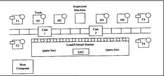
Company A is the first company to be analyzed. The FMS (Figure 8) in this case is not meeting any of the functional requirements mentioned in this paper. Therefore, the design matrix is the following:
FR1 FR2 0 0 0 0 DP1 DP2 = • FR1 = DP1 FR2 = DP2
It can be seen that the widely publicized flexible manufacturing system (FMS) is not the best design of all the manufacturing systems when compared to the three high level functional requirements of the manufacturing system design hierarchy. An FMS can be classified as a job shop [Black, 1991] because random order of part movement is permitted. Synchronous cycle time (FR1) is not met in the flexible manufacturing system, because most machines are design to do as many operations in one machine as possible. The result is long, asynchronous cycle times relative to the demand cycle time. Thus, it is necessary to schedule parts and machines within the FMS, just as it is in the job shop. This feature makes the FMS design difficult to link to other manufacturing systems. Since the FMS is automated, then operational flexibility is achieved by sophisticated and expensive cell control systems. The entire system may need to be “flushed” completely of parts in order to change between products. This results in increased setup time
Figure 8: Example of a FMS
Company B, which is a Toyota Production System manned cell meets the functional requirements defined in this paper. The design matrix for this type of system is as follows: FR1 FR2 X 0 0 X DP1 DP2 = •
A manned cell (Figure 9) is synchronous with the upstream elements because its cycle time is designed based on the takt time and the machine and operator work is standardized. At one of the companies studied with manned cells, the operator cycle time was constantly being achieved by the same operator and by other operators working during the second shift. The cell cycle time can be quickly altered to respond to changes in customer demand. The cell cycle time does not depend upon the machining time. Flexible work-holding devices, and tool changes in programmable machines allow rapid changeover from one component to the other. The machine and operator times are
FR1 = DP1 FR2 = DP2
uncoupled. Manned cells often use standard machines in an innovative way, which enables a flexible and low cost manufacturing cell to be designed. Since this cell is operated by a worker and not by a computer, the machine and cell control functions are uncoupled. No major computer programs need to be changed, no sophisticated machine interface or communications are required.
Figure 9: Example of a Manned Toyota Production System Cell
The other two manufacturing systems have met only one functional requirement. Transfer lines (Figure 10) are not flexible because the line is dedicated to only one product or may be two. They are used in mass production. These lines may be designed to be synchronous with the upstream production element (i+1). Specialized equipment, dedicated to the manufacture of a particular product is required. The investment cost of specialized machines and specialized tooling is high, as are the investment risks. The design matrix for a transfer line is the following:
FR1 FR2 X 0 0 0 DP1 DP2 = • FR1 = DP1
Figure 10: An Example of a Transfer line composed of four Turmats
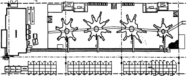
The last company (company D) to be studied uses a high volume, batch production manufacturing system. An example of this system is shown in Figure 11. The system is flexible because the machines are not dedicated to only one specific product. The machines can contain flexible fixtures to facilitate quick changeover from one product to other. Synchronization is not permitted because the machine functions attempt to encapsulate as many operations as possible. The machines are designed to be supermachines with minimal cycle times. As stated before, parts being produced in this system as well as the FMS need to be scheduled. This feature will cause the upstream and downstream processes (element i-1 and i+1) cannot be synchronized. Therefore, the design matrix for this type of system is:
FR1 FR2 0 0 0 X DP1 DP2 = • Saw Saw Saw Saw Lathe Lathe Lathe Lathe Lathe Broach Broach Broach Broach Broach Broach Broach Washer I.H. I.H. I.H. I.H. I.H. I.H. I.H. I.H. I.H. I.H. Draw Furnace Draw Furnace Draw Furnace S S S S S S S S S S S Grinder Washer Grinder Grinder Grinder Grinder Grinder Grinder 1 2 3 4 5 6 7 9 10 8 Crack Detection (Outsourced) Raw Material Finished Parts Figure 11: Example of a High Volume, Batch Production Manufacturing System
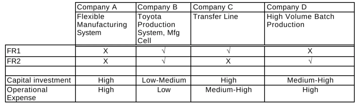
Table 1 summarizes the comparison made between the four different manufacturing systems and how they relate to the functional requirements defined in this paper. An “X” means that the functional requirement is not met, while the “√“ means that the functional requirement is met. The constraints on the design are also mentioned in Table 1. These are to minimize capital investment and operational expense.
Company A Company B Company C Company D
Flexible Manufacturing System Toyota Production System, Mfg Cell
Transfer Line High Volume Batch Production
FR1 X √ √ X
FR2 X √ X √
Capital investment High Low-Medium High Medium-High
Operational Expense
High Low Medium-High High
Table 1: Comparison of four different manufacturing systems
Summary and Directions for Further Research
The paper has introduced a new approach to manufacturing system design which has addressed several of the fundamental issues relevant to designing and implement new manufacturing systems. The axiomatic design approach is used as the basis for establishing a systematic design structure. The time interdependent and synchronous nature of production and the relationships between levels of a design hierarchy may be addressed through the axiomatic approach. The Functional requirements describe the objectives that a system must meet, while the axiomatic design hierarchy is used to address the hierarchical interdependence between the levels of production system, sub system and machine/operation design. This paper has shown that axiomatic design may be used to describe the fundamental design characteristics of manufacturing systems, cells and machines that accompany the design of the Toyota Production System and the Lean Manufacturing revolution, in general.
Suggested development relevant to this framework is twofold. The authors recommend further advancement of the machine design and cell control functional requirements and design parameters as an extension of the FRs and DPs presented herein. Secondly, it is recommended that the parameters and paradigms of new manufacturing system designs be stated in terms of FRs. By providing a clear definition of the FRs, the application and relevance of new technologies as DPs will become clearly and logically recognized.
References
Black, J T., The Design of the Factory of the Future, McGraw-Hill, 1991. Cochran, David S., The Design and Control of Manufacturing Systems, Auburn University, Alabama, 1994.
Fine, Charles H., New Manufacturing Technologies, Massachusetts Institute of Technology, 1989.
Parnaby, J., “Concept of Manufacturing System”, International Journal of Production
Research, Vol. 17, No.2, p. 123-135, 1979.
Suh, Nam P., The Principles of Design, Oxford Press, New York, 1990.
Suh, Nam P., Journal of Manufacturing Systems, Trends and Perspectives: Design and
Operation of Large Systems, Vol. 14 #3,1995.
Suzaki, Kiyoshi, The New Manufacturing Challenge, The Free Press, New York, 1987. Womack, James P., Lean Thinking: Banish waste and create wealth in your corporation, Simon & Schuster, New York, 1996.