Biomechanical Properties of Engineered Collagen Scaffolds
by
Christina M. Bonebreak
Submitted to the Department of Mechanical Engineering in Partial Fulfillment of the Requirements for the Degree of
Bachelor of Science in Mechanical Engineering at the
MASSACHUSETTS INSTITUTE OF TECHNOLOGY June 2005
© 2005 Christina M. Bonebreak. All rights reserved.
The author hereby grants to MIT permission to reproduce and to distribute publicly paper and electronic copies of this thesis document in whole or in part.
MA SSCHUSETTS INSTITE
OF TECHNOLOGY
JUN 0 8 2005
LIBRARIES
Signature of Author:
Department of Mechanical Engineering May 6, 2005
Certified by:
Approved by:
I -
-Simona Socrate Assistant Professor of Mechanical Engineering Thesis Supervisor
Ernest G. Cravalho Professor of Mechanical Engineering Chairman, Department Committee on Undergraduate Students
%
-
-i')
Biomechanical Properties of Engineered Collagen Scaffolds
by
Christina M. Bonebreak
Submitted to the Department of Mechanical Engineering on May 6, 2005 in Partial Fulfillment of the Requirements for the Degree of Bachelor of Science in
Mechanical Engineering
ABSTRACT
An experiment was performed to determine the effect of crosslinking on the stiffness of collagen scaffolds. Engineered non-crosslinked and dehydrothermally crosslinked chondroitin-6-sulfate collagen scaffolds were hydrated and loaded in tension, and their mechanical properties were compared. It was found that non-crosslinked scaffolds experience an average increase in weight after hydration of 10,353%, compared to 7,265% for crosslinked scaffolds. Hyperelastic material parameters were determined by the Arruda-Boyce eight-chain model, which was fit to the experimental data. This model predicted an average number of rigid links per collagen fiber of 1.3 and 1.21 for
crosslinked and non-crosslinked scaffolds, respectively. Additionally, the collagen fiber densities were found to be 2.92 x 10¹⁷ for crosslinked networks and 1.68 x 10¹⁷ for non-crosslinked networks.
These results can be applied to the changes that take place in the cervix at the onset of delivery. It is hypothesized that the crosslinking between collagen fibers in the cervix breaks down during preparation for delivery, allowing more fluid to enter the
extracellular matrix and weaken the tissue. By performing tension tests on cervix tissue in vivo, one can produce a theoretical fit to predict relevant collagen network parameters, which can be compared with those of non-pregnant cervical tissue to indicate the early
onset of cervical ripening. By being able to quantitatively assess a woman's risk of early cervical ripening, it may be possible to prevent premature births associated with cervical insufficiency.
Thesis Supervisor: Simona Socrate
Table of Contents
1.0 Introduction ...
5
2.0 Motivation ...
5
2.1 Clinical Introduction to Cervical Insufficiency ...
6
2.2 Symptoms ... 6
2.3 Diagnosis ... 7
2.4 Treatment ... 8
3.0 Biochemical Constituents of Cervical Tissue .
.
...
8
3.1 Extracellular Matrix of Cervical Tissue ...
8
3.2 Glycosaminoglycans ...
9
3.3 Proteoglycans ...
11
3.4 Collagen Structure and Function ...
12
4.0 Changes in Cervical Tissue During Pregnancy .
.
...
14
4.1 Changes in Proteoglycan Content ...
14
4.2 Collagen Degradation ...
16
4.3 Fluid Content ...
16
5.0 Materials and Methods ...
17
5.1 Testing apparatus ...
17
5.2 Collagen-GAG Scaffold Fabrication ...
19
5.3 Scaffold Specimen Preparation ...
20
5.4 Tensile Loading ...
21
6.0 Hyperelastic Model ...
21
7.0 Results...25
7.1 Hydration of Collagen Scaffolds ...
25
7.2 Tension Tests ...
27
7.3 Hyperelastic Model Parameters ...
28
8.0 Discussion. ...
30
8.1 Discussion of Crosslinking
on the Mechanical Properties of Collagen Scaffolds ...
30
8.2 Discussion of Error ...
31
9.0 Conclusion ...
32
REFERENCES
...
33
Appendix A: True stress vs. true strain for all engineered collagen scaffolds ... 36
Appendix B: Hydration chamber with adapter ...
37
Appendix C: Adapter to Zwick Machine ...
38
Appendix D: Grips for tensile loading of collagen scaffolds ...
39
Figures and Tables
Figure 2.1: Pelvic region of a pregnant female ...
6
Figure 2.2: Cervical shape progression during funneling ...
7
Figure 3.1: The extracellular matrix of the cervix and its macromolecule
constituents
...
9
Figure 3.2: Repeating disaccharide sequence of hyaluronan ...
10
Figure 3.3: Link between a GAG chain and its core protein in a proteoglycan
molecule
...
11
Figure 3.4: Illustrations of the tropocollagen molecule ...
12
Figure 3.5: Covalent intramolecular crosslinks between collagen molecules ... 13
Figure 3.6: Layered arrangement of collagen fibers in cervical tissue ...
13
Figure 4.1: Relative levels of dermatan sulfate and hyaluronic acid during various
stages of pregnancy ...
15
Figure 4.2: Hyaluronic acid levels at various gestational ages ...
16
Figure 4.3: Relative organization of collagen network in the non-pregnant and
pregnant cervix ...
17
Figure 5.1: Experimental setup of a collagen scaffold under tensile loading ... 19
Figure 6.1: Schematic of an eight-chain network in a cubic structure ...
22
Figure 6.2: Collagen fiber of statistical length R
0with N=5 rigid links ...
22
Figure 6.3: Schematic of a specimen in tensile loading ...
25
Figure 7.1: Percent weight change of crosslinked and non-crosslinked collagen
scaffolds
...
26
Figure 7.2: Average true stress vs. stretch for non-crosslinked chondroitin-6-sulfate
scaffolds
...
27
Figure 7.3: Average true stress vs. stretch for chondroitin-6-sulfate crosslinked
scaffolds
...
28
Figure 7.4: Experimental and theoretical stress vs. stretch for crosslinked
chondroitin-6-sulfate collagen scaffolds ...
29
Figure 7.5: Experimental and theoretical stress vs. stretch for non-crosslinked
chondroitin-6-sulfate collagen scaffolds ...
30
Table 3-1: Main constituents of human cervical tissue in non-pregnant women ... 9
Table 4-1: GAG content of the human cervix ...
14
Table 7.1: Percent change in scaffold weight due to hydration ...
26
Introduction
Three-dimensional, porous scaffolds have been used extensively as biomaterials for tissue synthesis and for in-vitro study of cell-scaffold interactions.' Scaffolds designed for tissue synthesis ideally provide the following characteristics: (i) a three-dimensional, highly porous structure to support extracellular matrix production, (ii) an architecture which promotes formation of the native tissue structure, (iii) a reproducible architecture of clinically relevant size and shape, and (iv) mechanical properties similar to that of the native tissue.2
Scaffolds made from collagen and glycosaminoglycans, significant constituents of the extracellular matrix (ECM), possess appropriate mechanical characteristics for use in tissue engineering. This study utilized porous, type I collagen-glycosaminoglycan scaffolds. The glycosaminoglycans (GAGs) intended for use in the fabrication of the scaffolds were chondroitin-6-sulfate, dermatan sulfate, and hyaluronic acid.
Dehydrothermally crosslinked and non-crosslinked scaffolds containing one of each of these GAGs were to be fabricated, and their mechanical properties to be studied under hydrated tensile loading. Due to mechanical failure of the equipment in which the scaffolds were constructed, only the chondroitin-6-sulfate scaffolds were successfully fabricated and used for experimental testing.
The objective of this study was to compare the mechanical properties of engineered collagen scaffolds with different types of GAGs and crosslinking. Because just one type of GAG scaffold was produced, only the effects of crosslinking were compared. A theoretical model for hyperelastic materials was fit to the experimental data to determine how crosslinking influences model parameters and scaffold stiffness.
2.0 Motivation
Cervical insufficiency is a physical condition in which a pregnant woman's cervix dilates prematurely, reducing her ability to carry the pregnancy to term. It is believed that
approximately 15% of all pregnancy losses that occur in the second trimester, defined as weeks 13 - 27 after conception, are a result of cervical insufficiency.3 This condition,
which is difficult to diagnose, presents a challenge to the medical community. The ultimate goal of this thesis study is to initiate the development of a quantitative method for diagnosing cervical insufficiency. By performing tension tests on collagen
scaffolds engineered to be mechanically similar to cervical tissue, we can obtain information about the way in which biomechanical properties affect cervical tissue
strength. With this material data, a finite element model of the soft tissue can be created to aid in the diagnosis of cervical insufficiency and prevent related premature births. The following section describes the condition of cervical insufficiency, the related symptoms, current methods of diagnosis, and forms of treatment.
2.1 Clinical Introduction to Cervical Insufficiency
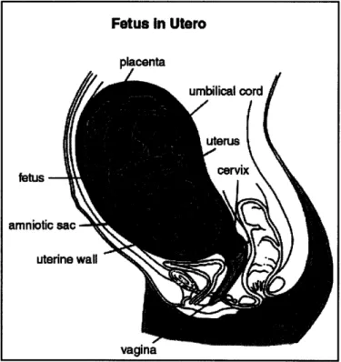
The cervix is an organ located at the entrance to the uterus that retains the fetus during pregnancy. Figure 2.1 shows the location of the cervix in the lower pelvic region of a pregnant female. In normal pregnancies, the cervix is stiff and remains closed throughout the gestation period, which is typically 38 weeks. It softens and dilates just before the onset of labor and allows the passage of the fetus. The human gestation period is typically around 38 weeks. For women with cervical insufficiency, the cervix is too soft to retain the fetus. This results in a reduction of a woman's ability to carry a pregnancy to term due to premature dilation.
Figure 2.1: Pelvic region of a pregnant female.
2.2 Symptoms
Natural dilation occurs prior to delivery through a process known as cervical ripening. During cervical ripening, the cervix tissue becomes less stiff as a result of hormone-triggered changes in the biochemical constituents of the tissue. Premature onset of these changes is a characteristic of cervical insufficiency, and may lead to a pre-term delivery, defined as birth before 28 weeks of gestation.
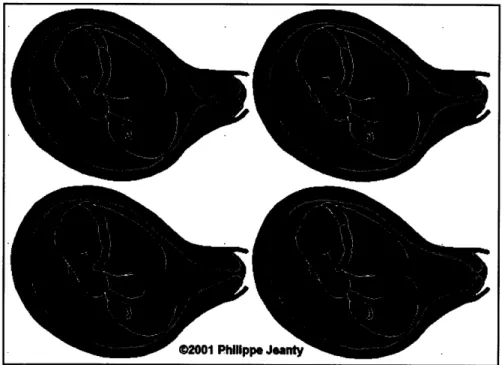
A symptom of cervical insufficiency is cervical funneling, a process by which the shape of the cervix changes as it softens. The funneling progression is characterized by a T, Y, V, U series of cervical deformation as illustrated in Figure 2.2. These internal changes
Fetus In Utero placenta fetus-amniotic uter Y-tp. -.
can be observed by ultrasound and Magnetic Resonance Imaging.3 Funneling is also
sometimes accompanied by a visible bulging of fetal membranes outside the cervix. Unfortunately, once these changes begin to take place, the onset of labor is difficult to stop. Labor associated with funneling of an insufficient cervix is typically spontaneous and occurs in the absence of palpable uterine contractions.4
Figure 2.2: Cervical shape progression during funneling.
2.3 Diagnosis
The medical community currently lacks an objective method of assessing a woman's risk for cervical insufficiency in the absence of a pre-term labor history. Diagnosis due to the observation of funneling is subjective, and is usually made after 16 weeks gestational time.5 In addition to the onset of cervical funneling, diagnosis can be made by examining the length of a woman's cervix. A study by ams et. al indicated that the length of the cervix is inversely related to the risk of preterm delivery; however, because of the discrepancy in the clinical data, cervical length as a diagnosis is still controversial.6
Obstetric history can also indicate a woman's risk for a pre-term birth. Women with a history of a pre-term birth before 28 weeks gestation experience a 10-fold increase in risk of having another pre-term delivery.3 Diagnosis for women who have previously
suffered a pre-term delivery is made prior to pregnancy. Women who experience injury to the cervix either from surgery or from complications during previous deliveries are also at risk for having an early onset of labor, and can be treated during early pregnancy.
p. Jeany
-2.4 Treatment
The most widely used methods of treating cervical insufficiency are bed rest, and a method of surgically closing the cervix called cerclage. The cerclage suture is typically applied to the cervix or lower abdomen at 13 - 14 weeks gestation, and removed after approximately 37 weeks to prepare for vaginal delivery. While the effectiveness of cerclage is unclear, studies indicate that 80-90% percent of pregnancies treated by this procedure produce viable births.5 If possible, cerclage should only be used when necessary, for infection or cervical injury may occur.
3.0 Biochemical Constituents of Cervical Tissue
Due to variations in what is considered to be a 'normal' cervix, physical characteristics alone cannot wholly identify a candidate for cervical insufficiency. A woman's risk for a pre-term delivery is dependent on biochemical factors in addition to the physical factors described above.
The role of the cervix during pregnancy is two-fold. First, it must be firm throughout the entire gestation period to retain the fetus. Second, it must become significantly less firm at the time of delivery to allow the developed fetus to pass through. The softening of the cervix that occurs just before delivery is due to changes in the biochemical content of the tissue. The biochemical constituents mainly responsible for the relative strength of the cervix during pregnancy include glycosaminoglycans, proteoglycans, collagen, and interstitial fluid, which combine to form the extracellular matrix of the cervical tissue. This section describes the structure and function of each component and the ways in which they contribute to the strength of cervix.
3.1 Extracellular Matrix of Cervical Tissue
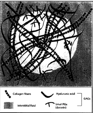
The extracellular matrix (ECM) is the structure on which cells attach and grow in connective tissue. The cervix, comprised mainly of connective tissue, gains its strength and rigidity from the ECM and the surrounding interstitial fluid.7 The main components of the ECM are the proteoglycans and their glycosaminoglycan sidechains and a collagen crosslinked network containing collagen type I and III fibrils.8 GAG molecules in the connective tissue form hydrated, gel-like substances in which the collagen proteins are embedded. This gel-like component of the ECM resists compressive forces imposed on the matrix, whereas the collagen fibers provide tensile strength. Figure 3.1 shows the network of collagen fibers, GAG components, and water that comprises the ECM.
Aq Collagen fibers
Interstitial fluid
\hi I-Hyaluronic add
GAGs
T
, Small PGs (decorin)Figure 3.1: The extracellular matrix of the cervix and its macromolecule constituents.
Table 3-1 lists the relative composition of the components in the ECM. The types of components will be discussed in more detail in further sections. Variations in the relative amounts and different types of macromolecules within the ECM and the way in which they are organized determine the mechanical properties of tissues.
Table 3-1: Main constituents of human cervical tissue in non-pregnant women
3.2 Glycosaminoglycans
Glycosaminoglycans, which comprise less than 10% by weight of ECM components, are polysaccharide chains composed of repeating disaccharide units.8'14 The role of the GAG
complex in the ECM is to provide mechanical support to tissues while allowing the diffusion of water-soluble molecules and the migration of cells. 14
Interstitial
Fluid 80%
Dry Tissue 20%
Collagen Glycosaminoglycans
-70% -0.2%
Type I Type III Dermatan Sulfate Hyaluronic Acid Other
-70% -30% -76% -11% -13%
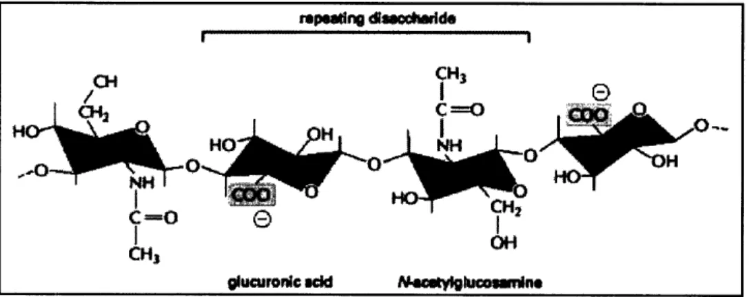
GAG chains are strongly hydrophilic due to the negative charge on their sugars. This characteristic increases their permeability, allowing them to imbibe large amounts of water and form gels at low concentrations. Permeability plays an important role in the mechanics of soft tissues, because fluid flow occurs under physiological loading conditions. '516 The resulting gels can occupy up to a thousand times its dry volume, filling most of the ECM space. The osmotic pressure induced in the ECM as it swells with water is what enables the surrounding tissue to withstand compressive forces. The simplest GAG structure is hyaluronic acid, which contains up to 25,000 units of a non-sulfated disaccharide. The structure of the basic disaccharide unit is shown in Figure 3.2.
re-ptng dasctoadd
i ii 1 i i i ''1ii iiiii
gluuronc wd Nlhftkm win:e
Figure 3.2: Repeating disaccharide sequence of hyaluronan.8
The repeating glucuronic acid and N-acetylglucosamine units in hyaluronic acid self-associate to form ordered helical structures that are considerably elastic. Additionally, extracellular matrices that contain large amounts of hyaluronic acid are elastic, yet easily deformed. As will be discussed in Section 4.1, the cervix becomes more elastic as it prepares for delivery by increasing hyaluronic acid production in the cervical tissue. Other common GAGs include chondroitin and dermatan sulfate. Chondroitin has the same basic structure as hyaluronic acid, with acetylgalactosamine replacing the N-acetylglucosamine. Chondroitin sulfate is formed when either the 4- or 6- hydroxyl groups are sulfated. The resulting GAG chains are known as chondroitin-4-sulfate or chondroitin-6-sulfate. In some situations, enzymes react with chondroitin sulfate to convert one of its acids, leaving an extra position to be sulfated. The resulting GAG is known as dermatan sulfate.
The majority of GAGs differ from hyaluronic acid in several ways. While hyaluronic acid is comprised of many units of the same disaccharide, all other GAGs tend to contain a number of different disaccharides arranged in chains of less than 300 sugars. The disaccharides in these GAGs are comprised of sulfated sugars, which allow them to covalently bind to other molecules.8 Glycosaminoglycans that covalently bind to proteins
are calledproteoglycans. The following section describes the function and most common types of proteoglycans.
3.3 Proteoglycans
Proteoglycans are macromolecules containing one or more glycosaminoglycan chain bound to a core protein. The purpose of the core protein is to facilitate the binding to collagen within the ECM, as GAG chains alone are unable to do so. Proteoglycans bind to collagen in order to enhance the crosslinking between fibrils and to regulate their spacing.
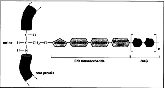
Except for hyaluronic acid, all GAGs are covalently attached to a protein in the form of a proteoglycan. Figure 3.3 depicts the link between a GAG chain and a core protein via a tetrasaccharide in a proteoglycan molecule.
Figure 3.3: Link between a GAG chain and its core protein in a proteoglycan molecule.8
While few classes of core proteins have been identified, proteoglycans can still vary greatly by the number and types of repeating disaccharide units that comprise their GAG chains. A proteoglycan that defines many of the characteristics of cervical tissue is
decorin. Decorin is the lowest weight proteoglycan, containing just one dermatan-sulfate
GAG chain, and receives it name because of the way it "decorates" collagen fibrils [b,c]. The structure of decorin contains a highly folded protein with a GAG chain extending out from it. The probable function of decorin is to regulate the formation of collagen fibrils and its organization within the ECM. Evidence also suggests that decorin may affect collagen fibril diameter, resulting in thinner fibrils.17
The interactions between collagen and proteoglycans are essential to the structural integrity of the ECM. The following section describes the structure and function of collagen in the ECM of cervical tissue.
(=O
*Wne
-l-I-C-
-O4
_
if-N
II
link tro ridd GAG
wc protin
I
3.4 Collagen Structure and Function
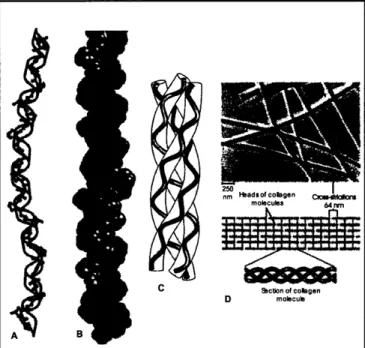
Approximately one-quarter of all proteins in the body are collagen. Collagen fibers weave together to form a network that provides structural support to tissues. These networks appear in various configurations throughout the body depending on its function. In soft connecting tissue, for example, the collagen is mainly of types I, II, and III. These types are formed when collagen molecules known as tropocollagens assemble into ordered polymers, or fibrils, which bundle together into a cable strand. Three cable strands then wind together to form a long, stiff triple-helix, as shown in Figure 3.4. Type I collagen is by far the most common, and is the principal collagen of skin and bone.8 In the soft connmlecting tissue of the cervix, collagen accounts for approximately 85% of the ECM dry mass, with 70% type I and 30% type III fibrils.18
Figure 3.4: A, B, and C are illustrations of the tropocollagen molecule. D illustrates the staggered organization of collagen molecules into a fibril formation.
It is important to note that after the collagen fibrils are formed, they are strengthened by covalent cross-linking to other collagen molecules. If cross-linking is inhibited, tissues experience a reduction in tensile strength and are easily stretched or tomrn. Figure 3.5 shows the intramolecular cross-linking between collagen fibrils.
. r
g/
nm aduBu!s
uugue. Clwn
molculs ^~~~~~~~~e 64nmr. C Sction of colagen D molecub0
9
3
Q
a
7 A 1V_r I~~~~~~~~~~~~~~~~~~~~~~~~~~~~~~~~~~~~~~~~~~~~~~~~~~~~~~~~~~~~~~~~~~~~~~~~~~~~~~~~~~~~~
Figure 3.5: Covalent intramolecular crosslinks between collagen molecules.8
According to Williamson, et. al, the tensile biomechanical properties of cartilage tissue are attributed primarily to the cross-linked collagen network of the ECM.19 Collagen orientation,2 0 disorganization,2 1 and degradation,2 2 all affect the tensile strength of various tissues.
Collagen fibrils form structures that support tensile forces, in contrast to GAGs, which resist compressive forces. Fibril-associated collagens, such as type IX and XII collagens, are responsible for the organization of collagen fibrils in different types of tissue by regulating the interactions between the fibers and other molecules in the matrix. In skin, the collagen network resembles a woven pattern that resists tensile stresses in multiple directions, as shown in Figure 3.6. In tendons, they are arranged in bundles and aligned
along the axis of tension. In cervical tissue, fibrils lay parallel to each other, but
perpendicular to fibrils in neighboring layers. These collagen fibers become disoriented as the cervix softens before delivery, allowing the tissue to stretch and become deformed.
5 R
Figure 3.6: Layered arrangement of collagen fibers in tadpole skin.8
I I
4.0 Changes in Cervical Tissue During Pregnancy
The non-pregnant cervix, comprised mainly of connective tissue, cannot sufficiently expand to allow the passage of a fetus. To allow the cervix to dilate, changes in the mechanical properties of cervical tissue take place over the last half to one-third of the pregnancy.7 Qualitatively, the cervix transforms from a stiff, rigid structure to one that is
soft and distensible, a process called cervical ripening. Cervical ripening is a process that results in the rearrangement of collagen molecules by a series of biochemical processes.23 This section describes how the mechanical changes that take place are a result of
alterations in the proteoglycan, collagen, and water content of the cervical tissue.
4.1 Changes in Proteoglycan Content
Proteoglycans interact with collagen to maintain the structure of the extracellular matrix in connective tissue. The bonds between proteoglycans and collagen enhance collagen cross-linking and regulate collagen fibril spacing. The work of Shimizu et. al determined that the glycosaminoglycan and proteoglycan content of postpartum cervical tissue differed from that of non-pregnant tissue. Rath et. al also observed that that the total amount of glycosaminoglycans increased during pregnancy. In particular, the amount of hyaluronic acid and chondroitin sulfate greatly increased in postpartum tissue, whereas that of dermatan sulfate slightly decreased. Data from Shimizu's experiment are found in
Table 4-1.24
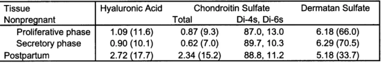
Table 4-1: GAG content of the human cervix. Numbers are mg (hexosamine)/ g
dry tissue. (Data in parenthesis are percent contents in total.)
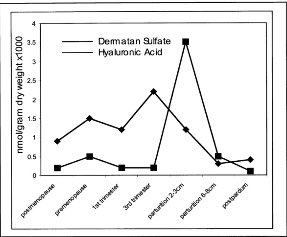
Rath et. al conducted a similar study and reported results in agreement with those of Shimizu. A graphical representation of his findings is shown in Figure 4.1.
Tissue Hyaluronic Acid Chondroitin Sulfate Dermatan Sulfate
Nonpregnant Total Di-4s, Di-6s
Proliferative phase 1.09 (11.6) 0.87 (9.3) 87.0,13.0 6.18 (66.0)
Secretory phase 0.90 (10.1) 0.62 (7.0) 89.7,10.3 6.29 (70.5)
4
Figure 4.1: Relative levels of dermatan sulfate and hyaluronic acid during various stages
of pregnancy.
The change in dermatan sulfate content is an essential characteristic of cervical ripening, because it regulates proper collagen spacing and crosslinking. Thus, the decrease in dermatan sulfate at ripening allows the cervix to soften.
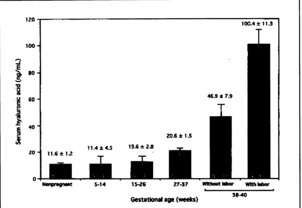
Further studied by Kobayashi et. al confirm an increase in hyaluronic acid concentration during pregnancy. The results of Kobayashi's investigation are shown in Figure 4.2.25 Hyaluronic acid affects the cervical tissue by disrupting the collagen network, which increases the spacing between fibrils and causes the tissue to imbibe water. The resulting disordered collagen network has lower tensile strength than its non-pregnant, organized counterpart.
0
o
3.50
X 3 - 3 a) 2.5 E LU 1.5 0 1 E 0.5 046.9 * 7.9
T
170 100.4A± 11.3T
100 80s -10 0 'E 60so-40 A 1.4 4.5 11. 11.6 17 = r 0-NImpl nw 5-14 156 Z7-37 wnmr Wh IorGstational age Ne) 3-40
25
Figure 4.2: Hyaluronic acid levels at various gestational ages.
4.2 Collagen Degradation
As one of the major components of cervical connective tissue, cross-linked collagen contributes greatly to the stiffness of the cervix. In the non-pregnant cervix, collagen fibers are organized into a tight, orderly network. In the pregnant cervix, collagen fibers become shorter, and the once tight, orderly network of collagen becomes loose and
disorganized.7
Studies performed by Sensstrom indicate that at delivery, the collagen concentration in the cervix is reduced by 30% compared to the non-pregnant cervix.2 6 Studies performed by Ekman show that there is twice as much collagenase activity in women with ripe
cervix. This suggests that collagenase is the enzyme responsible for the degradation of collagen fibrils and the remodeling of the collagen network during cervical ripening. During spontaneous cervical ripening, as experienced by one with an insufficient cervix, Ekman found that the speed of delivery was directly proportional to total collagen concentration. Thus, cervical collagen content may be an indicator of cervical insufficiency. 20.6: * 1.5
-r
m ZOt I - .,,,.,,,,i,=,,,,,~ ,=.i,,= T i .. __ __ I--- - --4.3 Fluid Content
Shimizu's study, as mentioned above in section 4.2, concluded that the production of hyaluronic acid in cervical tissue increased as delivery approached. Hyaluronic acid weakens the connection between fibronectin and collagen, contributing to the loosening of the collagenous framework.2 7 Fibronectin is an insoluble glycoprotein that helps to link molecules together in the ECM. The increase in hyaluronic acid causes the total fixed charge density in the cervix to increase, which leads the tissue to imbibe water and disrupt the collagen network by increasing the space between neighboring fibrils. The observations of Ekman et. al confirm the relationship between the increase in hyaluronic acid and water and the ripening of the cervix. They report that the increase in hyaluronic acid concentration and water content led to clinical findings of soft, swollen, and fragile consistency of the cervix in late pregnancy.
Due to the disruption of the collagen network upon the intake of water, it is hypothesized that tissue stiffness decreases as water content increases. Data collected by Aspden confirms that water intake is a primary source of tissue weakening. His studies found that an increase in water content by about 5% in the cervix may reduce the stiffness by a factor of two.7Figure 4.3 shows the disruption of the collagen network in pregnant cervix due to hyaluronic acid and water concentration gains.
NrON. .R:':t4N V117M. rrC.:,.?-NI7_ED t COL COEN. 'C-C-E.N
W'TH. C~.R~/;fIIED Cot.alGE wmi DISORGANIZED COLLACEI4FREGNA.T CERX I
Figure 4.3: Relative organization of collagen network in the non-pregnant and pregnant
5.0 Materials and Methods
To explore the relationships between the ECM components described in section 4.0 and their mechanical properties, a series of hydration and tension tests were performed. The following section describes the procedure by which collagen scaffolds were created and prepared for testing, the apparatus used for testing, and the procedure followed for loading the scaffold specimens in tension.
5.1 Testing apparatus
Tensile loading was performed on a Zwick machine (Zwick Z2.5/TSIS) outfitted with a 20N load cell. Original testing fixtures were designed for the tensile loading of collagen scaffold specimens. To test the scaffold in conditions mimicking an in vivo environment, a hydration chamber was designed and fabricated. The hydration chamber, measuring 8.5 x 8.5 x 16.5 cm, consisted of three clear acrylic walls held together by insoluble epoxy glue. The fourth wall could be removed and reattached to the chamber using four plastic clamps. An rubber O-ring was used to create a fluid seal around the edges of the fourth wall. A stainless steel adapter was designed to mount the chamber onto the Zwick machine. The adapter was inserted into the bottom of the chamber via an O-ring seal.
Stainless steel grips were designed specifically for the specimen size tested. Each grip consisted of two parts: one piece to mount onto the Zwick machine, and another piece to hold the specimen in place. Sandpaper was adhered to the inner-facing sides of each piece of the grip to provide friction and prevent slipping of the scaffold specimen. Finally, two screws were used to fasten the pieces together and hold the specimen firmly in place. Figure 5.1 shows the testing apparatus with a collagen scaffold specimen in place for tensile loading.
20 N load cell
Stainless steel grips
Clear acrylic fluid chamber
Collagen scaffold specimen
Clamp
Figure 5.1: Experimental setup of a collagen scaffold under tensile loading.
5.2Collagen-GAG Scaffold Fabrication
Collagen scaffolds were fabricated from collagen-gylcosaminoglycan mixtures using a procedure described by O'Brien et. al.28 Separate slurries were prepared with three
different glycosaminoglycans: chondroitin-6-sulfate, dermatan sulfate, and hyaluronic acid. Collagen-chondroitin-6-sulfate (GAG) scaffolds were prepared by blending micro-fibrillar type-I bovine tendon collagen (Integra Life Sciences, Plainsboro, NJ) and chondroitin-6-sulfate glycosaminoglycan (Sigma Chemical Company, St. Louis, MO) with 0.05 M acetic acid at 15,000 RPM in an overhead blender (IKA Works, Inc., Wilmington, NC). The resulting mixture was a white slurry of a co-precipitate
00
were made by substituting the chondroitin-6-sulfate with the same percent by weight of either dermatan sulfate of hyaluronic acid.
Each mixture was blended for 90 minutes at 4°C. A cooling system (Brinkman,
Westbury, CT) maintained the temperature of the suspension at 4°C throughout the entire mixing process to avoid fiber denaturization. Each of the slurries was then degassed under vacuum (50 mTorr) for 60 minutes to remove the many the visible air bubbles created during mixing.
After degassing, the slurries were prepared for freeze-drying as follows. First, the slurries were poured into aluminum pans (12.4 x 12.4 cm) (VirTis, Gardiner, NY) at room temperature and then placed into a freeze-dryer (Genesis, VirTis, Gardiner, NY). The temperature of the freeze dryer was decreased at a constant rate from 20°C to -40°C over a period of 65 minutes. The temperature was held constant at -40°C for 60 minutes, and then sublimated at 100 mTorr, 0°C for 17 hours. This process produced the porous structure of the collagen-GAG scaffold. This process has been shown to produce scaffolds with uniform pore size, which is that of the ice crystal that originally occupied the pore space while frozen.2 8 29
One of each type of collagen-GAG scaffold was stiffened using a physical crosslinking process called dehydrothermal treatment (DHT). This process took place inside a vacuum oven (Fisher IsoTemp 201, Fisher Scientific, Boston, MA) at 50 mTorr. The vacuum was maintained at 105°C for 24 hours to induce covalent crosslinks between the polypeptide chains of the collagen fibers, as previously shown in Figure 3.5. The remaining scaffolds were left uncrosslinked for comparison testing.
Completed scaffolds were placed in aluminum foil envelopes and stored in a dessicator at room temperature.
5.3 Scaffold Specimen Preparation
Specimens for mechanical testing were cut into strips measuring 1.5 x 3.5 cm from each collagen scaffold, and their dry weights were measured. Samples were cut at least 3mm away from the edges of the scaffold to avoid possible irregularities in pore size. Cut specimens were refrigerated overnight in a 1% phosphate buffer saline solution (PBS) according to a previous study indicating a 12 hour hydration time for collagen scaffolds. A wet weight of each specimen was taken following the hydration period. Prior to loading, the thickness and width of each specimen was carefully measured three times and averaged for accurate stress calculations. It was important that the scaffold remain in PBS while these measurements were taken to prevent distortion of the specimen due to fluid exiting the collagen structure. One end of a specimen was then inserted into a stainless steel grip, while the other end remained unattached. This grip was quickly mounted onto the Zwick machine, after which the specimen was lowered onto the bottom grip. PBS was gently squeezed onto the specimen throughout the mounting process to maintain the hydration and shape of the scaffold.
5.4 Tensile Loading
The TestXpert program was used in conjunction with the Zwick mechanical testing machine to perform the tensile loading tests. A reference position of y = 0 was determined by mounting the empty grips onto the Zwick and slowly lowering them together until a force of 0.001 N was measured. The grips were then removed and the scaffold specimen was mounted onto the Zwick in the manner described above in section 4.3. Tensile testing was performed by stretching the specimen at a constant nominal strain rate and measuring the corresponding load. Tension test trials were performed at displacement rates of 3 tm/sec, 15 m/sec, and 30 ptm/sec, after which it was determined that 15 jim/sec was an adequate rate. No pre-loading was performed, as the application of prestress may inadvertently un-kink some of the collagen fibers, resulting in a higher stiffness at low strain than what would otherwise be observed.3 0
6.0 Hyperelastic Model
Traditional elastic materials under tension exhibit a linear stress-strain relationship. Hyperelastic materials, such as collagen, produce a non-linear stress-strain curve characterized by two regions.3 0 At small strains, the material exhibits low stiffness as the collagen fibers un-kink and align themselves parallel to the stretch direction. The proteoglycan components of the ECM provide resistance to deformation of the collagen network at these levels of small strain. At higher strains, the collagen fibers have been sufficiently aligned and begin to stretch, resulting in a higher stiffness region. Unlike materials that exhibit a linear stress-strain relationship, the non-linear behavior of hyperelastic materials in tension is not as easily defined. A constitutive model derived from the mechanical behavior of long-chain molecules such as those found in fibrous collagen networks can predict the mechanical response of scaffolds in tension. A constitutive model developed by Arruda and Boyce effectively captures the three-dimensional stress-stretch behavior of macromolecular network materials by accounting for the behavior of collagen fiber networks. Other models provide stress-stretch
relationships for individual fibers while neglecting the importance of a cross-linked network on the total mechanical response, or by suggesting inadequate fiber network geometries. To account for the interaction of collagen fibers in a network, Arruda and Boyce propose using an eight-chain network model. This model determines the stresses imposed on a fiber network as shown in Figure 6.1 Collagen fibers extend inward along the diagonals of a cube from each of the eight vertices and converge at a centrally located
o 31
Figure 6.1: Schematic of an eight-chain network in a cubic structure. The model is
depicted in its undeformed state, in uniaxial tension, and in equi-biaxial tension.3 According to the Arruda-Boyce model, the stress-strain behavior of a collagen fiber network is primarily governed by the changes in entropy as the randomly-oriented network because more organized with stretching. The elastic behavior of the network
depends on two parameters: the number of rigid links, N, and the collagen fiber density, n. The collagen fiber density, n, is the property most directly associated with the initial stiffness of the scaffold. The number of rigid links in a collagen fiber of length R is shown in Figure 6.2.
Figure 6.2: Collagen fiber of statistical length Ro with N=5 rigid links. The average
length of each link is L.
The true stress-stretch relationship for a network whose fibers are arranged in an eight-chain configuration is given by
O-r
- C-6-.1
=-I
3 AC
(6.1)
L
where is a principal stress component, k=1.3807 x 10⁻²³ Nm/K is Boltzmann's constant, 0) = 298 K is the absolute temperature.3 4 Stretch induced by tensile loading is a ratio of the current length of the specimen to its original length. The chain stretch, Ac, can be described as the root mean-square of the applied stretches and is defined as
i
=2
2 +2
++ 2 )l/2,
1
=
-
+ +(6.2)where the three principal stretch directions are denoted by the subscripts 1, 2, 3. If we assume the collagen material to be incompressible, then each stretch value can be related to another via a conservation of volume:
i 2233 = 1 (6.3)
Stretch in the direction along the axis of tensile loading is always greater than one. In the case of uniaxial tension loading, as was performed in this experiment, the values of stretch in the other two directions are equal by symmetry. If the stretch along the direction of loading is taken to be A1, then
22 A =
J..
*(6.4)The Inverse Langevin function captures the dependence of collagen network organization on changes in entropy. Its inverse, the Langevin Function, is given by:
°(x)
_coth(x)
- (/x)
(6.5)
As the argument of the Inverse Langevin function, nears unity, the function asymptotically approaches infinity.3 0 As the chain stretch 2capproaches N, a locking
stretch is approached, after which increases in strain result in large increases in stress. These graphical trends indicate an increasing stiffness, described by the strain hardening response of the molecules within the collagen network.
The parameters n and N were determined via trial and error by applying the model to the experimental data and visually inspecting the quality of fit. Changing the value of n affects the initial modulus, as the collagen fiber density dominates low-stretch behavior. The number of rigid links, N, limits the amount to which the network can stretch, and so changing this parameter affects the high-stretch behavior.
In determining the values of the unknown parameters, the Arruda-Boyce model was fit to the average true stress and stretch of both the crosslinked and non-crosslinked samples. True stress is defined as the load applied to a specimen per unit deformed cross-sectional
Load
P
True Stress =
Load
=-
(6.6)
Deformed Area
a
The area of the specimen deforms as a result of the material's incompressibility.3 3 If one calculates the stress using the original cross-sectional area of the specimen, a, one is calculating the engineering stress, co :
P
c =
(6.7)
a0
Most mechanical testing software, including that used in this study, reports the stress to the user in the form of engineering stress. To convert engineering stress to true stress, one must first calculate the engineering strain. Engineering strain, e, is a function of the
stretch, X:
e = 1 (6.8)
l0
True stress, o, can then be defined as a function of the engineering stress, c0, and
engineering strain, e in the following way:
Cr = co (1 + e) (6.9)
The relationship between a, a, 1, and lo for a tensile specimen is shown in below in Figure 6.3.
Figure 6.3: Schematic of a specimen of original length lo and cross-sectional area a0 in
tensile loading.
These equations, which are true to all materials under tensile loading, as well as the hyperelastic model specifically designed for chain-linked networks, can be combined to predict and explain the behavior of a collagen scaffold in tension.
7.0 Results
Two variables were controlled in the fabrication of the collagen scaffolds: glycosaminoglycan content, and level of crosslinking. Collagen scaffolds were
constructed from three different glycosaminoglycans: chondroitin-6-sulfate, hyaluronic acid, and dermatan sulfate. Of these, the slurries were prepared such that one scaffold from each would be DHT crosslinked and another would be left uncrosslinked. Due to mechanical failure of the freeze-dryer, the only scaffolds processed for mechanical testing were the ones containing chondroitin-6-sulfate. A summary of the permeability measurements, tensile tests, and hyperelastic model parameter fittings performed on the crosslinked and non-crosslinked collagen scaffolds are presented in the following section.
7.1 Hydration of Collagen Scaffolds
To simulate the in-vivo conditions of cervical tissue, each collagen scaffold specimen was hydrated overnight in a 1% phosphate buffer saline solution. The weights of each specimen were measured before and after the hydration period. While weighing the specimens, it was observed that extra drops of solvent were often carried with the
scaffold onto the weight tray. To make the measurements as consistent as possible, each specimen was transferred to the scale along with the excess solvent, and the weight of the
solvent that remained on the tray after the measurement was taken was subtracted from the final weight of the scaffold. In this way, it could be assumed that each scaffold had the same amount of excess solvent as it was weighed, and all weights could be considered relative. Extra drops of solvent were observed to weigh approximately 40mg, or inpact an overall 4% change in the total percent change of the scaffold weight. Table 7.1
summarizes the effect of hydration on the weight of each type of scaffold.
Table 7.1: Percent change in scaffold weight due to hydration
Figure 7.1 graphically compares the hydration weight change of the crosslinked vs. non-crosslinked collagen scaffolds.
Figure 7.1: Percent weight change of crosslinked and non-crosslinked collagen scaffolds.
Weight of Non-Crosslinked Scaffolds (mg) Weight of Crosslinked Scaffolds (mg)
Before After Percent Change Before After Percent Change
8.7 915 10417.2 7.3 570 7708.2
7.9 860 10786.1 6.9 543 7769.6
7.2 717 9858.3 6.7 430 6317.9
Permeability of Collagen Scaffolds
- -- UU1 ZUUU -0 10000 cm
a
- 8000U
·C.)) 6000-a4000
¢;0
M 2000 0 * Non-Crosslinked * Crosslinked I 1 2 I I I I 3The results in Table 7.1 and Figure 7.1 show that the ratio of hydrated to dry weight for non-crosslinked scaffolds is higher than that for crosslinked scaffolds. This indicates that crosslinked collagen scaffolds swell less than non-crosslinked collagen scaffolds.
7.2 Tension Tests
Tension tests were performed on specimens from crosslinked and non-crosslinked chondroitin-6-sulfate scaffolds to determine the effect of crosslinking on scaffold stiffness. Figures 6.2 and 6.3 show the average results of the tests performed on each scaffold as true stress vs. stretch using equations 5.8 and 5.9. The error is plotted as ± ay,
the standard deviation of the stress.
0.04 0.035 0.03 X 0.025 0-0.02 C/, a) 0.015 0.01 0.005 0 1 1.05 1.1 1.15 1.2 1.25
Stretch
1.3 1.35Figure 7.2: Average true stress vs. stretch for non-crosslinked chondroitin-6-sulfate
0.04
Figure 7.3: Average true stress vs. stretch for chondroitin-6-sulfate crosslinked scaffolds.
As predicted in the theoretical model for hyperelastic materials, the stress-stretch curve for the collagen scaffolds are non-linear, and contain two regions of stiffness. An initial region of low stiffness occurs at small strains, followed by a region of increasing stiffness at large strains. For this material, large strains occur at stretch values between
approximately 1.1 and 1.3. The scaffolds did not reach high levels of strain due to tearing of the specimen at the grips during testing. For this reason, the ultimate tensile
strengths of each scaffold could not be measured. The two graphs are plotted on the same scale fr easy comparison.
7.1 Hyperelastic Model Parameters
The hyperelastic model described by Arruda-Boyce was fit to the experimental data by adjusting the theoretical values of the number of rigid links in a collagen fiber chain, N, and the collagen fiber density, n. A Matlab script was written to produce the values of the inverse lakmgevin function, the results of which were inserted into equation 6.8 to yield the theoretical stress.
After adjusting the values of n and N by trial and error, the best fit parameters were determined to be the following:
0.035 0.03 (0 CL . 0.025 0E 0) .02 C) a) L' 0.015 0.01 0.005 0
1
1.05
1.1
1.15
1.2
1.25
1.3
1.35
Stretch
Table 7.2: Best fit parameters for the Arruda-Boyce model
Crosslinked | Non-Crosslinked
Number of rigid links, N 1.3 1.21
Collagen fiber density, n (Il/m3) 2.92 x 10¹⁷ 1.68 x 10¹⁷
Figures 7.4 and 7.5 show the quality of fit of the theoretical model to the experimental data with these parameters. Small variations in either of these parameters led to large changes in the theoretical curve. Compromises were made between the initial stiffness region and the high stiffness region in order to achieve the best overall fit.
Figure 7.4: Experimental and theoretical stress vs. stretch for crosslinked
chondroitin-6-sulfate collagen scaffolds.
,%^
~rn-U.UOD
0.03
0.025
(U0-2 0.00-2
C._
(n I 0.015 -I.. *030.01
0.005
n
1
1.05
1.1
1.15
1.2
1.25
Stretch
0.035
Figure 7.5: Experimental and theoretical stress vs. stretch for non-crosslinked
chondroitin-6-sulfate collagen scaffolds.
8.0 Discussion
The following section discusses the results of the hydration measurements, tensile tests, and hyperelastic model parameter fittings performed on the crosslinked and non-crosslinked collagen scaffolds, followed by a brief discussion of error.
8.1 Discussion of crosslinking on the mechanical properties of collagen
scaffolds
The first set of measurements was taken to determine the effect of crosslinking on collagen scaffold hydration. Figure 7.1, which compares the percent change in scaffold weight before and after 24 hours hydration in PBS solution, shows that the
non-crosslinked scaffolds imbibed more water during this time than the non-crosslinked scaffolds. The average percent change for a non-crosslinked scaffold was recorded as 10,353 %, while the average percent change for a crosslinked scaffold was 7,265 %.
The tension tests performed on the two types of scaffolds confirmed that crosslinked collagen scaffolds are stiffer than non-crosslinked scaffolds, as predicted by the hydration tests. The stress-stretch curve for each scaffold consisted of two non-linear regions. Low stiffness occurred at small strains, followed by a region of higher stiffness at large strains.
0.03
0.025
13.E
0.02
._
a 0.015 U) 0.010.005
n 1 1.05 1.1 1.15 1.2 1.25Stretch
The initial low stiffness region appears to be longer for the non-crosslinked scaffolds than for the crosslinked scaffolds, which corresponds to a higher critical locking stretch of the collagen fibrils. Additionally, the latter region of the non-crosslinked curve appears to be
less stiff than that of the crosslinked curve. At a stretch of 1.2, the the non-crosslinked scaffold is under 0.013 MPa of stress, whereas the crosslinked scaffold is under 0.031 Mpa of stress, indicating a higher stiffness of the crosslinked scaffolds.
Due to the existence of covalent bonds between collagen fibrils in a crosslinked collagen network, crosslinked scaffolds exhibit greater stiffness than non-crosslinked scaffolds.
The covalent bonds provide resistance to tensile forces in addition to inhibiting the intake of water molecules, which disrupt the collagen fibers in a non-crosslinked network. The hyperelastic model developed by Arruda and Boyce allows one to quantitatively assess the differences between crosslinked and non-crosslinked collagen scaffolds. Through a method of trial and error, the physical parameters of collagen fiber density, n, and the number of rigid links in a collagen fiber chain, N, were estimated to provide a theoretical fit with the least amount of error. The results in Table 7.2 show that the number of rigid links is greater in a crosslinked scaffold than in a non-crosslinked
scaffold. This is expected, as crosslinking produces more covalent bonds between fibrils and decreases the full length of individual fibrils.
Table 7.2 also shows that the density of collagen fibers in crosslinked scaffolds is higher than that of non-crosslinked scaffolds. Non-crosslinked collagen networks are looser and imbibe more water, resulting in an overall ratio of collagen to solvent that is lower than that of crosslinked networks. This data suggests that collagen scaffold stiffness is directly proportional to the number of rigid links in a collagen fiber as well as the density of collagen fibers in a network.
8.2 Discussion of Error
Several factors may have attributed to error in this experiment. Many of the physical qualities of each scaffold specimen, including uniformity of collagen density, presence of air bubbles, and integrity of edges, were not easily controlled. Scaffold slurries were blended for 90 minutes, after which time it was possible that the components of each mixture were not evenly distributed. After the slurries were poured into the freeze-drying trays, care was taken to remove any remaining air bubbles; however, some bubbles are not easily discerned by the eye, and become apparently only after the freeze-drying process is complete. Human process error manifested itself in the cutting in dry scaffold specimens. The fragile collagen fibers were easily torn if the blade was not applied to the scaffold properly. Tearing was evident on the edges of a number of scaffold specimens. To account for this variation, all width and thickness measurements were taken from non-torn specimen sections.
The average of three measurements was taken for both the width and thickness values of each specimen to improve the accuracy of calculated stress, strain, and stretch
measurements. Plus and minus errors of these measurements would contribute to an average overall change of ±.001 Mpa, or 8% of the recorded stress.
As with many theories, the hyperelastic model is based on several assumptions, the most important of which is that the collagen fibers are arranged in an eight-chain network. Other models, which assume different network configurations, may have produced different parameter results. In addition, the stretch values used with the hyperelastic model assume that the material is incompressible, as described by equations 6.3 and 6.4, and that there are no viscous effects.
9.0 Conclusion
The objective of this experiment was to determine the effect of crosslinking on the stiffness of collagen scaffolds. Hydration and tension tests were performed on
crosslinked and non-crosslinked chondroitin-6-sulfate collagen scaffolds and the resulting mechanical properties were compared. By comparing the results from Figure 8.1, it was determined that non-crosslinked collagen networks experience a great percent weight change after hydration than crosslinked networks, indicating that non-crosslinked scaffolds imbibe more fluid. The intake of water into a scaffold has been observed by Aspden et. al to disrupt and weaken the collagen network. Figures 8.2 and 8.3 confirm this relationship, as it can be seen that the non-crosslinked scaffolds are less stiff than the crosslinked scaffolds. A theoretical model developed by Arruda and Boyce was fit to the experimental data to predict two collagen network parameters. Of these, it was seen that there are more rigid links per free length and a higher collagen fiber density in
crosslinked scaffolds than in non-crosslinked scaffolds.
These results have several implications regarding the changes that take place in cervical tissue at the onset of delivery. Studies performed by Shimizu et. al concluded that more
interstitial fluid is present in the cervix prior to delivery and post-partum. Thus, it can be hypothesized that crosslinking between collagen fibers in the cervix breaks down during preparation for delivery, allowing more fluid to enter the extracellular matrix and weaken the tissue. By performing tension tests on in-vivo cervix tissue, one can produce a theoretical fit to predict relevant collagen network parameters. These parameters can be studied and compared with those of non-pregnant cervical tissue to determine the amount of crosslinking and possibly indicate the early onset of cervical ripening.
REFERENCES
[1] O'Brien, F.J., Harley, B.A., Yannas, I.V., Gibson, L.J., 2005. The effect of pore size on cell adhesion in collagen-GAG scaffolds. Biomaterials, 26, 433-441.
[2] Woodfield, T.B.F., Malda, J., de Wijn, J., Peters, F., Riesle, J., van Blittersqijk, C.A., 2004. Design of porous scaffolds for cartilage tissue engineering using a three-dimensional fiber-deposition technique. Biomaterials, 25, 4149-4161. [3] Goldenberg, F.L., lams, J.D., Mercer, B.M., Meis, P., Moawad, A., Das, A., Cooper,
R., Johnson, F., 2003. What we have learned about the predictors of preterm birth. Semin Perinatol, 27 (3), 185-193.
[4] Creasy, R.K, Resnik, R. Maternal-Fetal Medicine, 4th ed. W.B. Saunders Company,
1984.
[5] Gabbe., S.G., Niebyl, J.R., Simpson, J.L. Obstetrics: Normal & Problem Pregnancies, 3r ed. Churchill Livingstone.
[6] Jay, D., Johnson, F., Sonck, J., Sachs, L., Gebauer, C., Samuels, P., 1995. Cervical
competence as a continuum: A study of ultrasonographic cervical length and obstetric performance. Am. Jour. Obst. Gynec., 172 (4), 1097-1106
[7] Aspden, R.M., 1987. The theory of fibre-reinforced composite materials applied to changes in the mechanical properties of the cervix during pregnancy. J. Theor. Biol, 130, 213-221.
[8] Alberts, B., Bray, D., Lewis, J., Raff, M., Roberts, K., Watson, J.D. Molecular Biology of the Cell, 3rd Ed. Garland Publishing.
[9] Kleissl, H.P., Van Der Rest, M., Naftolin, F., Glorieux, F.H., De Leon, A., 1988. Collagen changes in the human uterine cervix at parturition. Obsterics and Gynecology, 71 (4), 568-574.
[10] Ito, A., Mori, Y., Hirakawa, S., 1979. Purification and characterization of an acid proteinase from human uterine cervix. Chem. Pharm. Bull, 27, 969-973. [11] Rath,
W., Osmers, R., Severenyi, H.W., Stuhlsatz, H.W., Kuhn, W., 1991. The
Extracellular Matrix of the Uterus, Cervix and Fetal Membranes: Synthesis,
Degradation and Hormonal Regulatoin. Chapter 10: Changes of
glycosaminoglycans in cervical connective tissue. Perinatology Press.
[12] Rechberger, T., Uldbjerg, N., 1988. Connective tissue changes in the cervix during normal pregnancy and pregnancy complicated by cervical incompetence.
[13] Petersen, L.K., Uldbjerg, N., 1996. Cervical collagen in non-pregnant women with previous cervical incompetence. European Journal of Obstetric Gynecological Reproductive Biology, 67, 41-45.
[14] Wight, N., Heinegard, D., Hascall, V. Proteoglycans, from Proteoglycan Superfamily,ch. 2.
[15] Atkinson, T.S., Haut R.C., Altiero N.J., 1997. Journal of Biomechanical Engineering, 119, 400-405.
[16] Butler, S.L., Kohles, S.S., Thielke, R.J., Chen, C., Vanderby, R., 1997. Med Biol Eng Compu, 35, 742-746.
[17] Svensson, L, Heineg, D., Oldberg, 1005. Decorin-binding sites for collagen type I are mainly located in Leucine-rich repeats. Am. Soc. for biochemistry and molecular biology, 270 (35), 20712-20716.
[18] Ekman, G., Almstrom, H., Granstrom, L., Malmstrom, A., 1991. The Extracellular
Matrix of the Uterus, Cervix and Fetal Membranes: Synthesis, Degradation and
Hormonal Regulatoin. Chapter 8: Connective tissue in human cervical ripening.
Perinatology Press.
[19] Williamson, A.K., Chen, A.C., Masuda, K., Thonar, E., Sah, R.L., 2003. Tensile mechanical properties of bovine articular cartilage: variations with growth and r relationships to collagen network components. Journal of Orthopaedic Research, 21, 872-880.
[20] Kempson, G.F., 1979. Mechanical properties of articular cartilage. Adult articular cartilage, Tunbridge Wells, England: p333-414.
[21] LeRoux, M.A., Arokoski, J., Vail, T.P., Guilak, F., Hyttinen, M.M., Kirivanta, K., 2000. Simultaneous changes in the mechanical properties, quantitative collagen organization, and proteoglycan concentration of articular cartilage following canine menisectomy. J Orthop Res, 18, 383-392.
[22] Akizuki S., Mow, V.C., Muller, F., 1986. Tensile properties of human knee joint cartilage. J Orthop Res, 4, 379-392.
[23] Rai, J.., Schreiber, J.R., 2005. Cervical ripening, http://www.emedicine.com/med/topic3282.com
[24] Shimizu, T., Masahiko, E., Yosizawa, Z., 1980. Glycoconjuages
(glycosaminoglycans and glycoproteins) and glycogen in the human cervix uteri. Tohoku J. exp. Med, 131, 289-299.
[25] Kobayashi, H., Wei Sun, G., Tanaka, Yu., Kondo, T., Terao, T., 1999. Serum hyaluronic acid levels during pregnancy and labor. Obstetrics and Gynecology, 93 (4), 480-481.
[26] Sennstrom, M.B., Brauner, A., Bystrom, B., Malmstrom, A., Ekman, G., 2003. Matrix metalloproteinase-8 correlates with the cervical ripening process in humans. Acta Obstet Gynecol Scan, 82, 904-911.,
[27] Howard, J., Mechanics of Motor Proteins and the Cytoskeleton. Sinauer Associates, Massachusetts, 2001.
[28] O'Brien, F.J., Harley, B.A., Yanna, I.V., Gibson, L, 2003. Influence of freezing rate on pore structure in freeze-dried collagen-GAG scaffolds. Biomaterials, 25,
1077-1086.
[29] Pek, Y.S., Spector, M., Yannas, I.V., Gibson, L.J., 2003. Degradation of a collagen-chondroitin-6-sulfate matrix by collagenase and by chondroitinase. Biomaterials, 25, 473-482.
[30] Bischoff, J.E., Arruda, E.M., Grosh, K., 1999. Finite element modeling of human skin using an isotropic, nonlinear elastic constitutive model. Journal of
Biomechanics 33, 645-652.
[31] Boyce, M.C., Arruda, E.M., 2000. Constitutive Models of Rubber Elasticity: A Review. Department of Mechanical Engineering Center for Materials Science a and Engineering, Massachusetts Institute of Technology.
[32] Laboratory Module No.2: Tension Testing. Massachusetts Institute of Technology, Department of Mechanical Engineering, 2003.
[33] Danforth, D.N., Veis, M., Breen, H.G., Weinstein, J.C., Manalo, P1, Nov. 1974. The effect of pregnancy and labor on the human cervix: Changes in collagen, glycoproteins, and glycosaminoglycans. American Journal of Obstetric Gynecology, 120 (3), 641-651.
[34] Arruda, E.M., 1992. Characterization of the strain hardening response of amorphous polymers. Massachusetts Institute of Technology.