Publisher’s version / Version de l'éditeur:
Ships and Offshore Structures, 6, 3, pp. 211-221, 2011-09-15
READ THESE TERMS AND CONDITIONS CAREFULLY BEFORE USING THIS WEBSITE.
https://nrc-publications.canada.ca/eng/copyright
Vous avez des questions? Nous pouvons vous aider. Pour communiquer directement avec un auteur, consultez la
première page de la revue dans laquelle son article a été publié afin de trouver ses coordonnées. Si vous n’arrivez pas à les repérer, communiquez avec nous à [email protected].
Questions? Contact the NRC Publications Archive team at
[email protected]. If you wish to email the authors directly, please see the first page of the publication for their contact information.
NRC Publications Archive
Archives des publications du CNRC
This publication could be one of several versions: author’s original, accepted manuscript or the publisher’s version. / La version de cette publication peut être l’une des suivantes : la version prépublication de l’auteur, la version acceptée du manuscrit ou la version de l’éditeur.
For the publisher’s version, please access the DOI link below./ Pour consulter la version de l’éditeur, utilisez le lien DOI ci-dessous.
https://doi.org/10.1080/17445302.2010.544086
Access and use of this website and the material on it are subject to the Terms and Conditions set forth at
Discrete element analysis of ice loads on ships and structures
Lau, Michael; Lawrence, Karl P.; Rothenburg, Leo
https://publications-cnrc.canada.ca/fra/droits
L’accès à ce site Web et l’utilisation de son contenu sont assujettis aux conditions présentées dans le site LISEZ CES CONDITIONS ATTENTIVEMENT AVANT D’UTILISER CE SITE WEB.
NRC Publications Record / Notice d'Archives des publications de CNRC: https://nrc-publications.canada.ca/eng/view/object/?id=ace3365f-7471-416a-8edd-631c347ec307 https://publications-cnrc.canada.ca/fra/voir/objet/?id=ace3365f-7471-416a-8edd-631c347ec307
Discrete Element Analysis of Ice Loads on Ships and Structures
Michael Lau*
Institute for Ocean Technology, National Research Council of Canada St. John’s, Newfoundland, Canada
Karl P. Lawrence
PhD. Candidate, Department of Civil and Environmental Engineering, University of Waterloo Waterloo, Ontario, Canada
Leo Rothenburg
Chair/Professor, Department of Civil and Environmental Engineering, University of Waterloo Waterloo, Ontario, Canada
In this paper, the versatility of discrete element analysis (DEM) in modeling ice-related problems is discussed and further demonstrated using the results from the DEM works conducted by the National Research Council’s Institute for Ocean Technology (NRC-IOT) using a commercial code DECICE. These works include a wide range of structure and ice-ship interaction problems of current interest, i.e., ice loads on conical structures, jamming of floes at bridge piers, modeling of the mechanical behavior of ice rubble, pack ice stability and associated forces on offshore structures, rubble loads exerted on an inclined retaining wall, ridge keel resistance during seabed scouring, dynamic response of a moored conical drill-ship in ice, and ship maneuvering performance in ice. Representative simulations for each case are presented including load, motion and/or interaction process, whichever is appropriate. The simulations from DECICE were
compared with experimental data and found satisfactory in terms of accuracy and real-time simulation capability. The accuracy is important for design and engineering of marine structures and ships, whereas, the real-time simulation capability allows it to be used in marine simulators for personnel training and marine operation assessment. The performance of DECICE is also addressed and improve via the implementation of a new contact detection sequence and parallel considerations.
Key words: ice load; interactions; experiment; numerical; discrete element.
1. Introduction
With rapid advance of numerical techniques and computation hardware, numerical analysis and, in particular, the discrete element method (DEM) has evolved into a very powerful simulation tool for complementing analytical and experimental works. Applications of the discrete element method arise in mechanical, geotechnical and structural engineering
and, include, but are not limited to, simulations of particle motion, granular assemblies, ice-structure interaction, fracturing rocks, silo filling, impact problems, and so on (see for example Williams and O’Connor (1999), Lau et al. (2000), Han et al. (2000), Hashash et al. (2005); Hashash (2006), Wait (2001)).
Cundall (1971) first proposed the distinct element method as a means for simulating the behavior of jointed rocks. The details of the
procedure were outlined in Cundall and Strack (1978a, b). The method was generalized in a subsequent paper by Williams et al. (1985) who presented the discrete element method (DEM). Since then it has been applied to a wide range of problems via independent codes and commercial software.
DECICE is an acronym for Discrete Element Code for ice-related problems. It is a commercial code owned by Oceanic Consulting Corporation that is currently in use by the National Research
Council’s Institute for Ocean Technology (NRC-IOT) to study a variety of problems. The computer program was developed to solve complex solid mechanics problems involving multiple interacting bodies undergoing fracturing, and it is particularly appropriate for cases in which contact behavior between adjacent ice blocks governs the interaction processes.
DECICE simulations are complemented with model scale experimental tests conducted at the facility in order to exhibit the power of accurate numerical modeling. Representative tests include an ice-sheet impacting a conical structure, performance of survival craft in an ice-infested environment, maneuvering of a ship in sea ice, ridge keel resistance during scouring, forces exerted by pack ice, and ice arch formation. In this paper, the numerical and experimental models for each of these problems along with comparison of predicted and measured results will be discussed.
The original validations of DECICE
performed by Applied Mechanics Inc. in 1986 along with those conducted at IOT have clearly displayed the power of the tool in modeling discontinuum-based problems. Computer hardware, architecture, and algorithms, however, have continued to evolve in the period of time since its conception.
Multiprocessor and/or multi-core computers have been a driving force for the need of redevelopment and extension of algorithms to the high-performance computing (HPC) environment. The implementation of a new procedure for efficient contact detection as well as a parallel algorithm for the DEM is also discussed in this paper.
The layout of the paper is as follows. The next section provides a short summary of the DEM
followed by a series of numerical simulations, with experimental comparisons, performed at IOT in Section 3. Section 4 then discusses issues related to performance improvement of the tool and
experimental work.
2. Numerical procedure
The discrete element method, founded on the conservation of mass and energy and balance of momentum and moment of momentum, forms the theoretical basis of DECICE. The key conservation axioms in the form of Euler’s equations along with an expression for kinetic energy derived using Cauchy’s first law form the set of governing equations, which describe the movement and deformation of the system. These equations are transformed to a non-inertial frame of reference that is fixed to the center of mass of each element and is oriented so that the angular momentum with respect to the frame is zero. By writing the deformation of the body in the form a modal decomposition, a set of decoupled equations may then be obtained and solved via an explicit central difference scheme. A general finite element procedure may be employed to determine the modes and response of the structure to these modes. For a full discussion of the
governing equations and numerical procedure, refer to the DECICE theoretical manual (INTERA, 1986).
3. Simulation of ice-related problems
Six problems are addressed in this paper using DECICE. They include Ice sheet impacting a 60 conical structure; Ship maneuvering in ice; Ridge keel resistance during scouring; Performance of a survival craft in ice; Forces exerted by pack ice; and Ice arch formation. In the following subsections, a brief description of the problem along with details of the numerical model for each problem will be
discussed and results will be compared with experimental measurements whenever available. Another notable simulation conducted with
DECICE but not discussed here was completed by Murray et al. (1997) to investigate the loads exerted on a moored tanker in pack ice.
3.1. Ice sheet impacting a conical structure
Ice-cone interaction is a complex process that involves the interaction between the structure, the intact ice mass, and the broken ice fragments. A proper simulation of the interaction requires accurate modeling of failure modes, the cracking patterns, and the dynamics of the ice motion generated during the interaction. The original simulations performed by Lau (2001) used DECICE to model the interaction of an ice sheet with a 60 conical bridge pier. The results were verified with model tests carried out in the ice tank at IOT. For details of the experimental model, refer to the original publication.
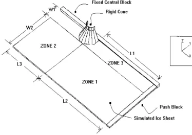
The discrete element model as shown in Figure 1 consisted of: (1) a rigid frictionless symmetry plane that imposes the appropriate boundary conditions in the symmetrical system; (2) a rigid 18-faceted cone modeling the smooth 60 conical structure; (3) a free-floating level ice plate modeled with 3-dimensional plate bending
elements; (4) a rigid driving block at the rear of the ice plate with a constant velocity of 0.5 m/s; and (5) a water foundation. Details of the simulations are not given here but failure modes and peak loads are discussed. In each of the simulations flexural failure was exhibited most frequently. Failure typically began with the formation of a major circumferential crack (MCC) through the centroid of the adjacent ice elements just after contact (see Figure 2). This was immediately followed by a number of
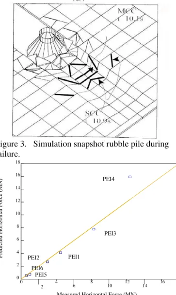
“subsidiary” circumferential cracks (SCC) in the nearby elements. As time progressed, the moving ice-sheet pushed the fragmented pieces up and around the cone, which led to the formation of a rubble pile in front of the structure (Figure 3).
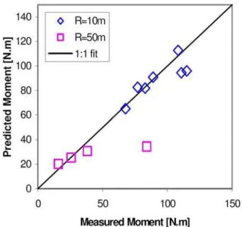
The failure mode predicted by the numerical simulation differs from that observed in the model tests which involved “subsidiary” cracking, a stable pileup of ice, and compressive shear failure but was consistent with that observed around a full scale conical structure, the Finnish Kemi I lighthouse, in the Gulf of Bothnia (Hoikkanen, 1985) where test conditions were comparable. The predicted and measured horizontal peak forces exerted on the
structure are shown in Figure 4. The numerical simulations slightly underestimate the peak force when flexural failure is dominant, i.e., Cases 1, 2, 3, 5 and 6, but despite this discrepancy in failure modes, the measured and predicted results are in good agreement.
Figure 1. Ice-cone interaction model using DECICE
Figure 2. Simulation snapshot depicting major circumferential cracks (MCC) and subsidiary circumferential cracks (SCC).
Figure 3. Simulation snapshot rubble pile during failure.
0 4
6 8 10 12 14 16 18
Measured Horizontal Force (MN)
P re d ic te d H o ri zo n ta l F o rc e (M N ) 18 16 14 12 10 8 6 4 2 0 1:1 fit PEI3 PEI1 PEI6 PEI4 PEI2 PEI5 2
Figure 4. Predicted vs measured peak horizontal force.
3.2. Ship maneuvering in ice
The numerical simulations conducted by Lau (2006) considered a 1:21 scale model of the Canadian icebreaker Terry-Fox moving forward andturning in level ice. The results show the effects of ice
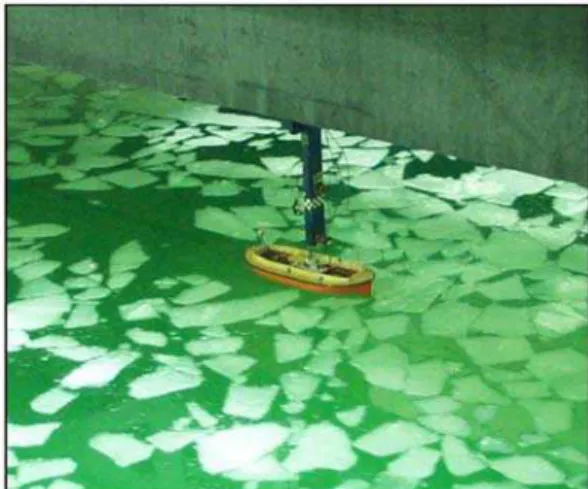
conditions and ship motion on the computed forces and moments. Complementing model experimental tests conducted at IOT (Lau and Derradji-Aouat, 2004) are shown in Figure 5.
Figure 5. Model test performed at NRC-IOT. The 3-dimensional numerical model created within DECICE (see Figure 6) consisted of: (1) a rigid moving element representing the Terry-Fox icebreaker; (2) a free-floating ice plate; (3) a rigid boundary; and (4) a water foundation. Various snapshots of the simulations are depicted in Figure 7. The interaction of the ship hull and leading ice edge consisted of breaking of the ice followed by the submergence and subsequent clearing. These results are also typical of that observed in the model tests. The predicted versus measured moment from each of the simulations/runs is given in Figure 8. In general, good agreement is observed between the numerical and experimental results at a turning radius of R=10 and R=50 meters. The predicted and measured moments versus yaw rate are also in good agreement as seen in Figure 9.
Figure 7. Snapshots of ship maneuvering in ice.
Figure 8. Predicted vs measured moment for a ship maneuvering in ice (R = turning radius).
Figure 9. Moment vs yaw rate for ship maneuvering in ice (R = turning radius).
3.3. Ridge keel resistance during scouring
During ice scouring, load that is exerted on the seabed by a floating ice feature depends on the ice feature characteristics, the driving force, and the seabed conditions. Modeling the ice feature as a single solid ice feature may be acceptable in the case of icebergs, but ice ridge keels may fail during interaction with the seabed and therefore limit the depth of scour and resultant load on the seabed. A preliminary investigation of the behavior of the ridge keel and seabed during scouring was presented in Lau et al. (2000).
The two dimensional version of DECICE was used to construct a model of the process which included: (1) a rigid plate representing the refrozen surface of the ridge keel; (2) a moving rigid plate representing the inclined seabed; (3) a total of 950 randomly generated uniform ice blocks which were allowed to float and compact beneath the rigid surface before movement of the seabed plate; and (4) a water foundation between the plates. The initial problem setup may be seen in Figure 10 before the plate was moved to determine the effect of the seabed inclination, trajectory angle, and ice-friction coefficient on the maximum nominal pressure.
Figure 10. Geometry of the ridge keel scouring problem.
Ten simulations were conducted and indicate that the magnitude of pressure increases with
increasing seabed plate penetration. The majority of stress was distributed on the leading area of the keel. As the trajectory angle of the seabed increases, so does the magnitude of contact pressure at ridge keel/seabed interface as a result of the increasing confinement pressure (see Figure 11). The magnitude of pressure also increases linearly with the coefficient of ice-friction (Figure 12).
Failure of the ice blocks was not permitted in these simulations but general trends were observed that govern the behavior of the ridge keel during scouring. A more realistic simulation could be performed by allowing the fracturing of ice blocks, using smaller contact areas/seabed
inclination/trajectory angles, using large block sizes relative to keel geometry, and using a more
appropriate modeling of the refrozen layer near the surface.
Figure 11. Nominal contact pressure vs trajectory angle.
Figure 12. Nominal contact pressure vs ice-friction coefficient.
3.4. Survival craft in ice
The next ice-related problem studied with DECICE in this paper is focused on measuring/predicting
Figure 13. Scaled experiment of survival craft.
Figure 14. DECICE model of survival craft. performance of a totally enclosed motor propelled survival craft (TEMPSC) which is used for
emergency situations in harsh environments. The scale model (depicted in Figure 13, see Lau and Re (2006) for complete details) was constructed at IOT and the numerical model (Figure 14) was composed using DECICE. With reference to Figure 14, the numerical model consisted of: (1) a rigid moving ship; (2) free-floating pack ice; (3) rigid boundary; and (4) a water foundation.
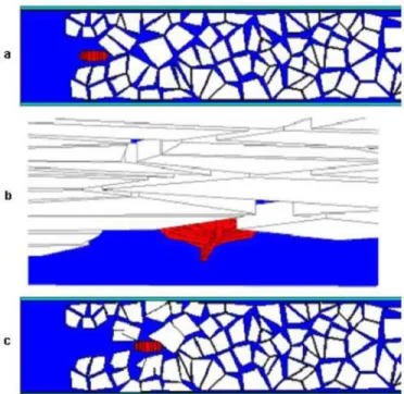
A total of 24 simulations were conducted consisting of small and/or large ice floes and various other mechanical properties of ice not discussed here. Typical snapshots of the start, mid, and end configuration of the ice floes are shown in Figures 15 and 16.
Figure 15. Small floes with low concentration at start time (a), mid-run (b), and end time (c).
Figure 16. Large floes with high concentration at start time (a), mid-run (b), and end time (c).
Interaction of smaller floes with the hull consisted of the floes being pushed aside or sliding under the hull whereas large floes were mainly pushed aside/ahead with a larger occurrence of accumulation in the front of the vessel in the latter
case. The predicted versus measured resistance shown in Figure 17 shows a good agreement between the results even though the initial geometrical ice configuration differed.
Figure 17. Predicted versus measured resistance. The name convention: <model scale>_<floe size in cm>_<ice concentration in 10th>.
3.5. Forces exerted by pack ice
In pack ice, although floe splitting is observed for larger floes, the dominant mode of failure is floe buckling (vertical displacement of the edges). McKenna et al. (1997) performed experimental, analytical, and numerical tests (using DECICE) to investigate the effects of floe thickness, size, and ice density on the loads and subsequent failure modes exerted by pack ice. A sample numerical simulation in which elements were generated to promote out of plane failure is shown in Figure 18. The numerical and experimental results were then used to develop an empirical relationship between all factors involved. This empirical relationship, along with peak structure forces from DECICE tests, is plotted versus the floe size in Figure 19. The results indicate the transition between floe buckling and splitting occurs in the range of 0.5-1.0 meter.
Figure 18. Flow ice buckling snapshots.
Figure 19. Peak force versus flow size estimates from experiments, DECICE, and analytical solutions.
3.6. Ice arch formation
The final ice-related problem discussed in this paper is related to ice-arch formation and jamming on bridge piers. The purpose of the analysis was to develop a relationship between the critical ice concentration to floe size, pier spacing, and inter-floe friction. A total of 81 numerical simulations
were conducted by Schachter and Spencer (1994) with the 2-dimensional version of DECICE in which each of the parameters was varied. A typical
snapshot of the simulations is shown in Figure 20.
Figure 20. Snapshots of floe ice simulations. An empirical formula was developed using the results to predict the critical concentration at which ice-arches will likely form. The effect of inter-floe ice friction is shown in Figure 21.
Figure 21. Empirical relationship derived from DECICE results displaying relationship between inter-floe friction and critical concentration (A = floe size/area, D = diameter of pier, S = center to center pier spacing).
Concentrations above these critical curves would lead to stable arching while values closer would promote an unstable arch. The results are expected to compare well with the physical model of Calkins (1978) for a friction coefficient of 0.6.
3.7. Summary of results
The results of these simulations show that DECICE is a very powerful tool which may be utilized both in understanding the fundamental mechanisms driving many physical processes, developing
empirical formulae, and estimating quantities which may be extremely difficult to measure or predict in practice. With the increased use and capability of modern computing systems, numerical simulations and in particular discrete element analysis is becoming a viable and cost effective means of performing fast and effective design calculations.
4. High performance computing considerations
Over the past two decades, advancements in numerical/computational methods and
advancements in available computing environments have led to the need for a partial redevelopment of the DECICE code. In the text that follows we
address both the algorithm and parallel improvement of DECICE to improve the performance of the algorithm and increase the applicability of the tool to large-scale problems.
4.1. Algorithm improvement
The application of the DEM in general has been somewhat limited in the past few decades due to the computational cost involved. The bulk of this computational effort is concentrated during the “contact detection” stage. In order to ensure correct mechanical behavior of a system of elements, contact forces must be generated when elements come into contact with one another. But maintaining and updating correct details of contact for
polyhedral elements is somewhat of a cumbersome task as is evident by the large amount of literature available on the subject in various fields of research.
The original DECICE algorithm took a very robust approach to contact detection, implementing an algorithm that checked all potential vertex-to-face and edge-to-vertex-to-face contacts with a hidden feature approach (see DECICE theoretical manual
(INTERA, 1987)). Another commercially available software, 3DEC, developed by Itasca Consulting Group using the theory presented by Cundall (1971, 88) utilizes a well known approach which involves finding a common-plane (CP) which maximizes the gap between the elements. Cundall (1988) showed that for larger numbers of and more complex
elements, the CP approach yields better performance than does the direct testing method. However, iterations, which were required to position and orientate the CP, limited the performance of the algorithm.
Recently, Nezami et al. (2004) described a method founded on a mathematical analysis by which to orientate the CP that did not require iterations and hence dramatically increased the speed of the original CP algorithm. A multi-step contact detection procedure consisting ofspatial domain decomposition and axis-aligned bounding boxes; and this fast common-plane (FCP) algorithm presented by Nezami et al. (2004) forms the basis of the updated algorithm within DECICE. The new algorithm required a complete redevelopment of the algorithms and data arrays associated with the contact detection within DECICE. Note that although the detection scheme has changed, the underlying algorithm remains unchanged, so that the accuracy of the method is not affected. The new data storage arrays were developed to facilitate quick access to the most commonly used variables during contact detection and with a future parallel
implementation in mind. In addition, ideas from real-time collision theory were implemented to estimate a time-of-collision to further reduce the need for unnecessary calculations.
4.2. Parallel improvement
A preliminary study of the advantages of a parallel implementation of DECICE on a multiprocessor system has been conducted and acomplete study is
currently under investigation. The property of the DEM method that has limited the scalability of the simulations to larger number of processors to date is generally the need for large storage. Simulations on multiprocessor systems would then require large communication times and/or large amounts of local data to be copied into memory locations for each processor to manipulate. Zhao (2006) reported a speedup of only 3-5 times on 32 processors of the NCSA supercomputing system (SMP and NUMA architecture) for up to 98,000 particles. Their approach consisted of each or a set of processors working on sub-divided regions of space and then coalescing at the end of each DEM step to update elements along the boundaries of these regions.
In DECICE, the parallel implementation is focused at the algorithm level rather than by spatial subdivision. The fact that the governing equations are decoupled suggests that a parallel
implementation would be advantageous at least during the solution scheme. The recent
redevelopment of the contact detection algorithms provided a means by which to implement a parallel-approach to this portion of the DEM.
4.3. Simulation results and discussion
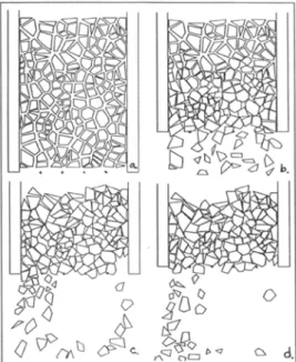
To determine the effect of the new contact detection algorithm on the performance of DECICE a test was conducted which involved 100, 200, 300, 400, and 500 free-falling randomly-generated deformable blocks. The elements were generated above an open box and calculation proceeded until the elements had settled. Snapshots of the initial and final
configuration for the 500-element case are shown in Figure 22.
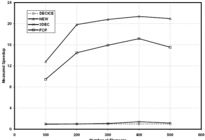
For comparison purposes, the simulation was also conducted using the commercially available DEM package 3DEC. The numerical parameters used in 3DEC were matched to those used in
DECICE so that a direct comparison could be made. The speedup results of the simulations are depicted in Figure 23. Simulation times are scaled by the corresponding simulation time of the original DECICE algorithm. The results indicate that 3DEC
performs comparably with the original DECICE algorithm and the new algorithm performs
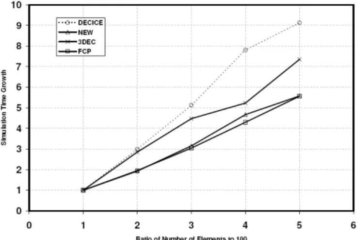
approximately 21 times faster for 500 elements. The true measured execution times for this case are 2.05 hours for the new algorithm and 43.05 hours for the old algorithm, so the simulation time reduces from a few of days to a few hours. In all cases the speedup over the original algorithm is dramatic (at least an order of magnitude). Further analysis shows that the rate at which simulation time increases has also decreased by a factor of 2, mostly due to the implementation of the FCP algorithm (see Figure 24).
Figure 22. Initial (left) and final (right)
configuration of 500 randomly generated elements free-falling into a box.
Figure 23. Measured speedup of new contact detection scheme.
Figure 24. Simulation time growth versus the number of elements.
The parallel implementation is currently under investigation. The modifications to the serial version of DECICE have been completed and initial simulations for 500 elements indicate a speedup of 2 on 4 processors and 4 on 8 processors. The
measured speedup is expected to increase for a large number of elements and a larger number of
processors. The limitations are currently being addressed in more detail.
5. Conclusions and recommendations
The Institute for Ocean Technology (IOT, formerly the Institute for Marine Dynamics) of the National Research Council of Canada (www.nrc.ca/iot) has upgraded and carried out numerical analysis using a discrete element commercial code DECICE to supplement its experimental efforts to solve a variety of ice load problems.
This paper is divided into two main sections. The first focuses on displaying the versatility of the numerical simulation tool DECICE for ice-related problems and the second addresses the performance of the tool. Six ice-related were modeled using DECICE including (1) an ice sheet impacting a 60 conical structure; (2) a ship maneuvering in ice; (3) ridge keel resistance during scouring; (4)
performance of a survival craft in ice; (5) forces exerted by pack ice; and (6) ice arch formation. Corresponding experimental models of problems
(1), (2), (4) and (5) above conducted at the IOT are in good agreement with the numerical results. An empirical relationship between inter-floe friction and critical concentration derived using DECICE simulations of problem (6) compare well with an existing physical model (Calkins, 1978) and the preliminary investigation in (3) exhibits the dependence of contact on seabed trajectory angle, coefficient of friction, and ridge penetration depth. DECICE has shown great potential for both making qualitative and quantitative predictions of complex physical processes involving multiple interacting bodies.
The performance of the tool has been increased dramatically by the addition of more advanced contact detection algorithms and parallel considerations. Speedup over the original algorithm and the only other commercially available software, 3DEC, are approximately 21 times faster for a relatively small number of elements. Larger and more complex problems may be studied in the future as a direct result of this increase in performance.
Acknowledgements
The authors would like to acknowledge the financial support of the Natural Sciences and Engineering Research Council of Canada (NSERC), the National Research Council of Canada (NRC), and the University of Waterloo. All experimental tests were conducted at the NRC-IOT in collaboration with other researchers and staff whose help is also greatly appreciated.
References
Calkins, D. J. (1978), “Arching of model ice floes at bridge piers”, Proceedings of IAHR’78 Symposium on Ice Problems, Lulea, Sweden. Cundall, P. A. (1971), “A computer model for
simulating progressive, large scale movements in blocky rock systems”,
International Symposium on Rock Fracture, Nancy, France.
Cundall, P. A. (1988), “Formulation of a three-dimensional distinct element model. Part I. A scheme to detect and represent contacts in a system composed of many polyhedral blocks”, International Journal of Rock
Mechanics, Mineral Science, and
Geomechanics Vol. 25 (3), pp. 107–116. Cundall, P. A. (1978a), and Strack, O. D. L., “The
distinct element method as a tool for research in granular media”, Report to the National Science Foundation Concerning NSF Grant ENG76-20711 Part I.
Cundall, P. A. (1978b), and Strack, O. D. L., “The distinct element method as a tool for research in granular media”, Report to the National Science Foundation Concerning NSF Grant ENG76-20711 Part II.
Han, K., Peric, D., Crook, A. J. L., and Owen, D. R. J. (2000), “A combined finite/discrete element simulation of shot peening process. Part I: Studies on 2D interaction laws”, Engineering Computations Vol. 17 (5), pp. 593–619.
Hashash, Y. M. A. (2006), “Large-scale numerical simulations via parallel computing: an application using discrete element modeling of granular material”, NCSA Strategic Applications Program Status Report 03/28/2006.
Hashash, Y. M. A., Nezami, E. G., and Ghaboussi, J. (2005), “DBLOCK3D: A 3-d discrete element analysis code for simulation of granular media and soil-machine interaction” Workshop on Granular Materials in Lunar and Martian Exploration, Orlando, Florida. Hoikkanen, J. (1985), “Measurement and analysis of
ice force against a conical offshore structure”, Proceedings of the 8th
International Conference Port and Ocean Engineering under Arctic Conditions, Narssarssuag, Greenland, Vol. 3, pp. 1293-1222.
INTERA (1986), “DECICE theoretical manual”, Denver, Colorado, INTERA Information Technologies Environmental Division. Lau, M. (2001), “A Three dimensional discrete
element simulation of ice sheet impacting a 60-degree conical structure”, Proceedings of the 16th International Conference on Port and Ocean Engineering under Arctic
Conditions, POAC’01, Ottawa, Ontario, Canada, Vol. 1, pp. 431-440.
Lau, M. (2006), “Discrete element modeling of ship maneuvering in ice”, Proc. of the 18th
International Symposium on Ice, IAHR Ice Symposium 2006, Sapporo, Japan, Vol. 2, pp. 25- 32.
Lau, M. and Derradji-Aouat, A. (2004) “Preliminary modeling of ship maneuvering in ice”, 25th Symposium on Naval Hydrodynamics, Marineering Ltd., St. John’s, Newfoundland, Canada.
Lau, M., Phillips, R., McKenna, R.F., and Jones, S.J. (2000), “Discrete element simulation of ridge keel resistance during scouring: A preliminary study”, Proceedings of the 2nd Ice Scour and Arctic Marine Pipelines Workshop, Mombetsu, Hokkaido, Japan. Lau, M., and Re, A. S. (2006) “Performance of
survival craft in ice environments”,
Proceedings of the International Conference and Exhibition on Performance of Ships and Structures in Ice, Banff, Alberta, Canada, July 16-19.
McKenna, R. F., Spencer, D., Lau, M., Walker, D., and Crocker, G. B. (1997), “Modeling the forces exerted by pack ice consisting of small floes”, Proceedings of the 14th
International Conference on Port and Ocean Engineering under Arctic Conditions,
POAC’97, Yokohama, Japan, Vol. 4, pp. 329-338.
Murray, J. J. and Spencer, D. S. (1997), “A
simulation model for a turret moored tanker in pack ice cover”, Proceedings of the 14th International Conference on Port and Ocean Engineering under Arctic Conditions,
POAC’97, Yokohama, Japan, Vol. 4, pp. 127-140.
Nezami, E. G., Hashash, Y. M. A., Zhao, D., and Ghaboussi, J. (2004), “A fast contact
detection algorithm for 3-d discrete element method”, Computers and Geotechnics Vol. 31, pp. 575–587.
Schachter, M. and Spencer, D. (1994), “Parameters influencing ice arch formation”, National Research Council of Canada Institute Report IR-1994-05.
Wait, R. (2001), “Discrete element models of particle flows”, Mathematical Modeling and Analysis, Vol. 6 (1), pp. 156–164.
Williams, J. R., Hocking, G., and Mustoe, G. G. W. (1985), “The theoretical basis of the discrete element method”, NUMETA ’85, Numerical Methods of Engineering, Theory and
Applications, Rotterdam.
Williams, J. R., and O’Connor, R.(1999), “Discrete element simulation and the contact problem” Archives of Computational Methods in Engineering, Vol. 6 (4), pp. 279–304. Zhao, D (2006). “Three dimensional discrete
element simulation for granular materials”, PhD Thesis, University of Illinois at Urbana-Champaign.