I,
Autonomous Adaptive Acoustic Relay Positioning
by
Mei Yi Cheung
B.A., Columbia University, 2011
Submitted to the Department of Mechanical Engineering
in partial fulfillment of the requirements for the degree of
Master of Science in Mechanical Engineering
at the
MASSACHUSETTS INSTITUTE OF TECHNOLOGY
September 2013
©
Massachusetts Institute of Technology 2013. All rights reserved.
Author ...
. . ..
..
Departmen
' I&
f
anical Engineering
August 15, 2013
Certified by
Franz S. Hover
Finmeccanica Career Development Professor of Engineering
Thesis Supervisor
A ccep ted b y ...
. ...
David E. Hardt
Chairman, Department Committee on Graduate Students
Autonomous Adaptive Acoustic Relay Positioning
by
Mei Yi Cheung
Submitted to the Department of Mechanical Engineering on August 15, 2013, in partial fulfillment of the
requirements for the degree of
Master of Science in Mechanical Engineering
Abstract
We consider the problem of maximizing underwater acoustic data transmission by adaptively positioning an autonomous mobile relay so as to learn and exploit spatial variations in channel performance. The acoustic channel is the main practical method of underwater wireless communication and improving channel throughput and reli-ability is key to improving the capabilities of underwater vehicles. Predicting the performance of the acoustic channel in the shallow-water environment is challenging and usually requires extensive modeling of the environment. However, a mobile relay can learn about the unknown channel as it transmits. The relay must balance search-ing unknown sites to gain more information, which may pay off in the future, and exploiting already-visited sites for immediate reward. This is a classic exploration vs. exploitation problem that is well-described by a multi-armed bandit formulation with an elegant solution in the form of Gittins indices. For an autonomous ocean vehicle traveling between distant waypoints, however, switching costs are significant. The multi-armed bandit with switching costs has no optimal index policy, so we have de-veloped an adaptation of the Gittins index rule with limited policy enumeration and asymptotic performance bounds. We describe extensive shallow-water field experi-ments conducted in the Charles River (Boston, MA) with autonomous surface vehicles and acoustic modems, and use the field data to assess performance of the MAB deci-sion policies and comparable heuristics. We find the switching-costs-aware algorithm offers superior real-time performance in decision-making and efficient learning of the unknown field.
Thesis Supervisor: Franz S. Hover
Acknowledgments
Firstly, I would like to thank my thesis advisor, Professor Franz Hover, whose guidance and insight made this project possible. I was first introduced to the challenging field of marine robotics when I joined his group two years ago and have learnt a great deal from him since. I would also like to thank all my labmates for their help and expertise, especially Eric Gilbertson, Josh Leighton and Brooks Reed. An autonomous kayak takes many people to launch and it has been an equally collaborative experience at Hovergroup. Finally, I thank my parents, I would not be here without their support, and my brother, who always encourages me to strive harder.
Thanks also to Toby Schneider and Mike Benjamin at MIT for all their help with using Goby and MOOS, and to Keenan Ball and Sandipa Singh at WHOI for their quick responses and help when we had questions about the Micro-modems. I also thank MIT Sailing Master Franny Charles and Gerard for their patience and understanding with all the marine robots careening about the MIT Sailing Pavilion. This work is supported by the Office of Naval Research, Grant N00014-09-1-0700, the National Science Foundation, Contract CNS-1212597, and Finmeccanica.
Contents
1 Introduction 17
1.1 Background and Motivation . . . . 18
1.1.1 Marine Vehicles: Applications and Autonomy . . . . 18
1.1.2 Underwater Acoustic Communication . . . . 20
1.1.3 Formulation and Motivation . . . . 23
1.2 Prior W ork . . . . 25
1.3 Sum m ary . . . . 27
2 Problem Formulation 29 2.1 The Canonical Multi-Armed Bandit . . . . 29
2.1.1 Problem Formulation . . . . 30
2.1.2 An Optimal Solution: Gittins Indices . . . . 32
2.2 A Heuristic Adaptation for Switching Costs . . . . 32
2.3 Bernoulli and Normal Reward Processes for Adaptive Relay Positioning 34 3 Field Implementation and Experiments 39 3.1 Autonomous Surface Vehicles . . . . 40
3.1.1 Vehicle Hardware . . . . 41
3.1.2 MOOS-Based Software Architecture . . . . 41
3.1.3 Acoustic Modems . . . . 43
3.2 Autonomous MAB . . . . 44
3.3 Autonomous MABSC . . . . 44
4 Acoustic Communications in Shallow Water 47
5 Experimental Results 53
5.1 Autonomous MAB ... 53
5.2 Autonomous MABSC ... ... 56
5.3 MABSC on the Hybrid Tour Data ... 58
5.4 MABSC with Synthetic Data ... 61
6 Conclusion 65
A Figures 67
B Tables 71
List of Figures
1-1 Saab Seaeye's ROV Falcon controls a robotic shark to gently bite an actor; The Bluefin HAUV builds a point cloud mesh model of a ship hull to inspect for mines; Hydroid's AUV REMUS tracks a great white shark for Discovery Channel's Shark Week. Image Sources: (a) http: //www.rovworld. com/article2886.html, (b) http://web. mit. edu/hovergroup, (c) http: //www. whoi. edu/oceanus/viewArticle.
do?id=173392 ... ... 19
1-2 Work-class ROVs like SMD's ATOM are often used for construction and maintenance; ROV VideoRay is a small specialized robot for in-spection and survey; WHOI's Hybrid Oceanographic Research ROV Nereus is able to operate in different modes. Image Sources: (a) http://www.smd.co. uk/products/work-class-rovs/atom. htm, (b)
http://www.videoray.com/homepage/professional-rovs/videoray-pro-4.
html, (c) https://www.whoi.edu/main/nereus . . . . 20
1-3 Hydroid's REMUS is well-suited to methodical surveying and map-ping, OceanServer's Iver2 is a low-cost, single man-portable system, and the Bluefin HAUV was designed for hull inspection with a high-resolution imaging sonar. Image Sources: (a) http: //www. whoi. edu/ instruments/viewInstrument .do?id=1759, (b) http://iver-auv.
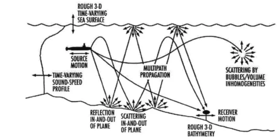
1-4 Illustration of possible sources of interference in the acoustic channel. Many of these sources are difficult to model and predict, especially in an environment where environmental properties may vary widely in time and space. Image Source: http://www.rjeint. com/acousticTerms.
htm... ... 22
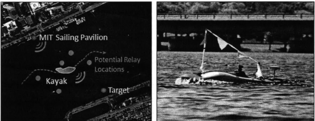
1-5 Illustration of adaptive relay positioning problem implemented in the Charles River, Boston MA with an autonomous surface vehicle (right) towing an underwater acoustic transducer as the mobile relay. A fixed source node is present at the MIT Sailing Pavilion and a fixed desti-nation node is another kayak station-keeping across the river. . . . . . 24
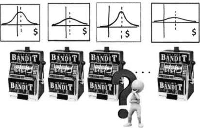
2-1 Illustration of multi-armed bandit gambling analogy. The gambler makes a series of sequential decisions between one-armed bandits (arms of the multi-armed bandit) with unknown reward distributions. Esti-mates of the unknown distributions are built up by the gambler over multiple observations, and inform his future decisions. Image Sources:
http: //thetechnologicalcitizen. com/, http: //www.thegadgetexperience.
com/slot-machines/... ... 30
2-2 Gittins indices computed for a Bernoulli reward process (N=750, 0=0.95) 35
2-3 Gittins indices for Normal reward distribution with zero mean and unit
variance. . . . . 37
3-1 Charles River Basin (Boston, MA) with Autonomous Surface Vehi-cle Nostromo inset. Relay locations are shown in white. Source and destination locations are shown in red. . . . . 40
3-2 Autonomous surface vehicle Nostromo (left) in Boston Harbor and with Silvana (right) on the Charles River. . . . . 41
3-3 Illustration of MOOS and MOOS-IvP software architecture used for communications and control. . . . . 42
3-4 Micro-modem Multi-Channel PSK Stack with Power Amplifier (left) and 25kHz Omnidirectional Transducer Towfish (right) Source: http: // acomms.whoi.edu/umodem/ . . . . 43 4-1 Altimetry data of the Charles River, Boston in the area visited by the
relay. Scale shown is from 0 to 10m. The depth of the Charles River varies from 2 to 12m, with the deepest area in a channel on the South (Boston) side of the river. . . . . 48 4-2 Impulse response of the matched filter showing various multipath
ar-rivals after the main signal. The mean squared error of the modem's equalizer is another measure of the interference in the channel
(Ap-pendix B ). . . . . 48
4-3 SNR-In for data transmissions from MAB field experiment, Trial 2. Direction of transmission is shore to relay (left) and relay to destination
(right). . . . . 49
4-4 SNR-In for initial ten transmissions at each of nine relay locations. Range is from 0 to 20dB. . . . . 49 4-5 Final [packet success rates, variance of the estimate, number of
sam-ples] at nine bandit locations and for both autonomy trials. . . . . 50
4-6 SNR-In for data transmissions from HybridSetA (left) and B (right). Direction of transmission is source to relay. Site number is shown in black and final packet success rates estimates over the whole mission is shown in red. . . . . 50
4-7 SNR-In values over time for HybridSetA (left) and B (right). Grey lines represent lost packets. Sites are visited in the same order and data is for source-to-relay transmission. . . . . 52
4-8 HybridSetA Grouped SNR-In values over time (left), with overall aver-age noted at right, and Grouped Packet Success Rates against SNR-In
(right). Data is for source to relay transmission only. Each averaging group consists of five transmissions on location. . . . . 52
5-1 Evolution of the Gittins Index, the mean, and the variance of the estim ate for Trial 2. . . . . 54
5-2 Cumulative bytes transmitted for Trials 1 and 2 and extrapolations of
initial touring survey. . . . . 55 5-3 Improvement in cumulative bytes transmitted with respect to
extrap-olations of initial touring survey . . . . 55
5-4 Cumulative data transmitted as a function of time in minutes for Trial
2, with periods of vehicle transit shown in gray. . . . . 56 5-5 Cumulative packet success rate by observation, where unity indicates
100% success rate. . . . . 57 5-6 Cumulative data transmitted by mission time. . . . . 57 5-7 Total sum of squares error by observation. . . . . 58 5-8 HybridSetA (left) and B (right) cumulative performance of MAB, MABSC
and tuned c-greedy and c-decreasing algorithms by observations, where unity indicates 100% success rate. . . . . 59 5-9 HybridSetA (left) and B (right) cumulative transmissions by calculated
mission times. In left, the plot of c = 0.010 overlaps with c = 0.1, r =
0.25. . . . . 60 5-10 HybridSetA and B Total Sum of Squared Differences over time, summed
over all sites. . . . . 61
A-1 SNR-In values against mission time for HybridSetB Source-to-Relay
(left) and Relay-to-End (right). Grey lines represent lost packets. Sites are visited in the same order. . . . . 67 A-2 Mean-squared-error (MSE) out of the Equalizer against mission time
for HybridSetA (left) and B (right). Grey lines represent lost pack-ets. Sites are visited in the same order and data is for source-to-relay transm ission. . . . . 68
A-3 SNR-Out values against mission time for HybridSetA (left) and B
(right). Grey lines represent lost packets. Sites are visited in the same order and data is for source-to-relay transmission. . . . . 68
A-4 Mean-squared-error (MSE) out of the Equalizer (left) and SNR-Out values (right) for HybridSetB Relay-to-End transmission. Grey lines represent lost packets. Sites are visited in the same order. . . . . 69
List of Tables
5.1 Computation Time by Lookahead Horizon and Field of Probabilities 63 5.2 Percentage Reward Rate Improvement Over Touring Survey . . . . . 63
B.1 Autonomous Kayaks Components and Dimensions . . . . 71
Chapter 1
Introduction
The ocean is a challenging environment for humans and robots alike. Features of interest may vary over wide temporal and spatial scales, the environment is often un-known and harsh as pressures and temperatures reach extremes, and familiar robotic senses like sight and touch degrade underwater. Large advances in marine robotics and autonomy have been made in recent years as scientists and engineers have risen to the challenge, motivated by the immense potential for robotics to further study of the ocean and usage of its resources. As individual vehicles, their navigation, control and communications, mature into commercially-available technology, the next step lies in enhancing the control and behavior of fleets of vehicles, so that they may organize and collaborate in a way that enhances the capabilities of the group as a whole.
Effective underwater communication is vital to the development of multi-vehicle applications in the ocean, and the main mode of wireless data transmission underwater is acoustic. Electromagnetic waves are severely attenuated underwater, rendering ra-dio frequency (RF) communications inappropriate and optical communications short range (on the order of a hundred meters). However, the acoustic channel is noto-riously unreliable and highly dependent on the properties of the medium. Modern channel modeling, estimation and coding schemes go a long way towards improving channel performance (e.g. [46], [16], [40]), but cannot directly address the channel's dependence on spatially variable environmental properties - temperature, salinity, bathymetry, surface conditions etc., and the physical location of the acoustic nodes.
This thesis considers the problem of maximizing the performance of the acoustic channel in an unknown environment by deploying a mobile, autonomous acoustic relay that adaptively positions itself so as to exploit horizontal spatial variability in the channel. As the relay learns about the channel's properties by transmitting, this can be posed as a classic exploration vs. exploitation scenario with an elegant and practical solution.
1.1
Background and Motivation
We briefly review common marine robotic platforms and applications, and the atten-dant technical challenges.
1.1.1
Marine Vehicles: Applications and Autonomy
Robotic ocean vehicles are primarily utilized by three general industries; oil and gas, defense and security, and scientific research (Fig. 1-1). In 2010, the oil industry rep-resented 50% of global ROV sales and 20% of global AUV sales [11]. Development of vehicles capable of survey and inspection as well as equipment installation, manip-ulation and repair tasks has been motivated by dwindling shallow-water oil reserves and the move towards technically-challenging deep water wells [50]. In the security industry, robotic vehicles are well-suited to time-consuming tasks or dangerous tasks such as patrolling, reconnaissance, ship-hull inspections and mine counter-measures
(MCM) (e.g. [4], [20]). Vehicles equipped with various sensors and able to
commu-nicate with static sensor networks are often used to collect oceanographic data on a large scale and in harsh environments. Increased availability of salinity, temperature, density, chemical and biological composition data help researchers better understand and model ocean processes [30]. Imaging, sonar or vision-based, allows vehicles to capture evidence of new marine species as well as uncover underwater archaeological
sites [21].
Remotely-operated vehicles (ROVs) are designed for remote human control and use with a support vessel or platform. Power and commands are transmitted from
(a) Saab ROV Falcon (b) MIT Bluefin HAUV (c) Hydroid REMUS
Figure 1-1: Saab Seaeye's ROV Falcon controls a robotic shark to gently bite an actor; The Bluefin HAUV builds a point cloud mesh model of a ship hull to inspect for mines; Hydroid's AUV REMUS tracks a great white shark for Discovery Chan-nel's Shark Week. Image Sources: (a) http://www.rovworld.com/article2886. html, (b) http://web.mit.edu/hovergroup, (c) http://www.whoi.edu/oceanus/ viewArticle.do?id=173392
the support vessel to the vehicle through a long tether, while sensor data such as real-time video is transmitted back. Tethered ROVs operate underwater without the constraints of battery life and computing capacity but the presence of the long tether complicates vehicle dynamics and increases operating costs and complexity. High bandwidth data transmission through the tether enables real-time imaging, manip-ulation and pilot control, thus ROVs are generally used to replace divers for deep water equipment construction and repair tasks [51]. Commercial ROVs range from large, versatile work-class vehicles like Soil Machine Dynamics (SMD) QUANTUM and ATOM, to the specialized man-portable inspection and survey ROV VideoRay (Fig. 1-2). In general, ROVs offer real-time sensing, power and fine pilot control underwater while being relatively time, manpower and capital-intensive to operate.
However, as underwater vehicle technology matures and the price of vehicles de-creases, human and ship support dominate as the major cost driver of underwater ocean operations. Autonomous underwater vehicles (AUVs) are able to operate in-dependently of a support ship or platform for long periods of time (Fig.1-3). They have varying levels of autonomy, ranging from pre-planned lawnmower-style paths for survey and data collection to adaptive behaviors that respond to environmental stimulus. AUVs must handle their own low-level control and navigation, mission-level decision-making and operate sensor payloads for oceanographic data collection,
(a) SMD ATOM (b) VideoRay (c) WHOI Nereus Figure 1-2: Work-class ROVs like SMD's ATOM are often used for construc-tion and maintenance; ROV VideoRay is a small specialized robot for inspec-tion and survey; WHOI's Hybrid Oceanographic Research ROV Nereus is able to operate in different modes. Image Sources: (a) http://www.smd.co.uk/ products/work-class-rovs/atom.htm, (b) http ://www. videoray. com/homepage/
professional-rovs/videoray-pro-4.html, (c) https://www.whoi.edu/main/ nereus
optical and sonar-based imaging. Currently, the majority of AUVs sold are rated for water depths less than two hundred meters, with the emphasis on small, light vehicles
[11]. Their operational capability is limited by onboard computing power, battery life
and means of actuation. Gliders are one type of AUV that move by adjusting the vehicle's buoyancy. Using fixed wings, they are able to travel in a vertical yo-yo pat-tern with very little power consumption. Hybrid AUVs such as the Bluefin HAUV and WHOI's Nereus are able to move autonomously underwater, but communicate with the support vessel through a thin, high-bandwidth fiber-optic cable.
1.1.2
Underwater Acoustic Communication
Wireless communication with underwater autonomous vehicles is key to increasing their ability and reliability, and the acoustic channel is the main practical carrier for wireless underwater data transmission over long distances. Radio frequency waves are heavily attenuated underwater (on the order of tens of meters), and high band-width optical communications is limited to short ranges (about one hundred meters in clear water). The acoustic channel is a wide-band packet-based erasure channel. Latency is high as the speed of sound in water is approximately 1500m/s and data
(a) Hydroid REMUS (b) OceanServer Iver2 (c) MIT Bluefin HAUV
Figure 1-3: Hydroid's REMUS is well-suited to methodical surveying and map-ping, OceanServer's Iver2 is a low-cost, single man-portable system, and the Bluefin HAUV was designed for hull inspection with a high-resolution imaging sonar. Image Sources: (a) http: //www. who i. edu/instruments/viewInstrument. do?id=1759, (b) http://iver-auv.com, (c) http://www.bluefinrobotics.com/
products/hauv/
rates are low. The channel is wide-band, in the sense that the bandwidth is not neg-ligible with respect to the center frequency, and cannot accommodate multiple users or signal multiplexing easily. Numerous sources of signal interference make packet decoding a challenge, for example, Doppler effects from source and receiver motion, wave refraction due to the nonlinear sound-speed profile, and reflection and scattering from the surface, bottom and particles within the volume creating numerous multi-path arrivals (Fig. 1-4). These sources may vary widely in time and space and are heavily dependent on local environmental properties including density, temperature, salinity of the water as well as bathymetry and surface conditions. In harbor and man-made environments, structures and ambient noise can be a problem. Given suf-ficient knowledge of the environment, ray and beam-tracing may be used to predict the effects of multipath as well as the location of "shadow-zones" and acoustic wave guides in which refraction of sound waves create zones where acoustic waves do not enter or exit respectively ([381,[10]). These methods are generally conducted in the two-dimensional vertical plane where the sound-speed profile is well-defined.
The signal's attenuation and spreading loss is frequency-dependent, as delay oc-curs over many milliseconds due to the low speed of sound in water. Background ambient noise from sources like wind, waves and shipping may be approximated as Gaussian but not white, while site-specific noise such as snapping shrimp found
ROUGH 3-D
TM-VARYING SEA SURFACE
PROFILE
REECON SATRN EOWE
I-AND-DUT MOTION
OF PLANE M-N- ROUGH OFUSILEVBOYME 3-D Y
Figure 1-4: Illustration of possible sources of interference in the acoustic channel. Many of these sources are difficult to model and predict, especially in an environment where environmental properties may vary widely in time and space. Image Source:
http: //www.rjeint .com/acousticTerms.htm
only in certain areas of the world often contain significant non-Gaussian components ([46],[6]). Thus, the Signal-to-Noise ratio (SNR) of the channel is a function of the frequency and distance, and in particular, the available bandwidth decreases with transmission over increased distances. This means dividing long distances into mul-tiple hops allows for transmission at higher data rates over each link and for lower total power consumption [46]. In recent years, development of advanced channel es-timation and error correction schemes have gone a long way towards increasing the robustness of the point-to-point acoustic channel (see [45], [16] for recent surveys).
Coherent phase-shift-keying (PSK) modulation schemes work well with sparse adap-tive decision feedback equalizers (DFEs), and much work has been done on improving the real-time performance and robustness of the channel estimator and equalizer. A fundamental trade off exists between choosing to send more data in a larger packet, where error correction schemes can be more sophisticated with less overhead but the time taken to encode, transmit and decode the packet is longer and may incur more channel interference and packet loss, and sending a smaller packet for a lower overall data rate but more reliability in packet success. In general, acoustic modem param-eters such as modulation type, error correction scheme, packet size and transmission power may be tuned heuristically to improve performance.
1.1.3
Formulation and Motivation
Many ocean applications are well-suited to the use of a team of vehicles collaborat-ing and sharcollaborat-ing information. Trackcollaborat-ing and pursuit of dynamic ocean processes (e.g. fronts and plumes), marine animals and vehicles is a time-critical application in which multiple vehicles may contribute greater robustness, tracking precision and maneu-verability (e.g. compared to long towed arrays). Oceanographic surveys require data collection over large time and spatial scales, and multiple vehicles may be able to resolve spatio-temporal ambiguity encountered by a single vehicle. As the availabil-ity of vehicles increases and human/ship support costs become proportionally more important, deploying additional vehicles in order to complete missions faster or mul-tiple missions at the same time becomes increasingly cost efficient. The effectiveness of a team of underwater vehicles hinges on the performance of the acoustic channel for critical communications. In order to motivate the development of sophisticated behaviors and decision-making for groups of vehicles, we address the goal of improv-ing the performance of the acoustic channel in an unknown environment, specifically, maximizing the cumulative data transmitted through the channel over the course of a mission.
For most missions in an unknown ocean environment, measuring the water prop-erties, bathymetry and other environmental variables for detailed modeling of the acoustic channel is time-consuming and undesirable. Day-to-day fluctuations in sur-face and sea conditions as well as the large spatial scale of ocean applications make accurate modeling a challenge. In shallow-water and man-made environments, multi-path interference results in significant variability in space, which may be exploited by acoustic nodes if the variations in channel performance was known. A key insight lies in recognizing that acoustic nodes can learn about the statistics of the channel (i.e. SNR, packet success rate) at their current location while receiving and transmitting. This is often exploited by static acoustic sensor networks with adaptive networking algorithms. For the purpose of improving acoustic communications during a multi-vehicle mission, we consider the case of deploying a mobile acoustic relay. The relay
is free to travel to different locations and learn about the performance of the chan-nel; i.e. the point-to-point physical channel in space. While the acoustic modems may correct for errors and interference within the channel itself, a mobile relay is able to adapt to link variations in physical space. Fig. 1-5 shows this setup in the Charles River, Boston MA. The mobile relay's goal is to maximize the cumulative transmissions from the source to the destination node, given no prior knowledge of
the environment.
Figure 1-5: Illustration of adaptive relay positioning problem implemented in the Charles River, Boston MA with an autonomous surface vehicle (right) towing an underwater acoustic transducer as the mobile relay. A fixed source node is present at the MIT Sailing Pavilion and a fixed destination node is another kayak station-keeping across the river.
Thus, the relay must balance searching unknown sites to gain more information, which may pay off in the future, or exploiting already-visited sites for immediate reward. This is a classic exploration vs. exploitation problem that is well-described by a multi-armed bandit optimization framework. We formulate the multi-armed bandit for the problem of adaptive acoustic relay positioning and apply an elegant optimal solution in the form of Gittins indices. However, for an autonomous ocean vehicle traveling between distant waypoints, the time costs of traveling between locations (switching costs) are significant. The multi-armed bandit with switching costs has no optimal index policy, so we develop an adaptation of the Gittins index rule with limited policy enumeration and asymptotic performance bounds.
1.2
Prior Work
Though a conceptually simple problem, adaptive positioning in the spatial horizontal field so as to improve the performance of the acoustic channel has not been sys-tematically studied before. Depth adjustment was studied recently by Detweiler et al. [18], following the discussion of Akyildiz et al. [3], with modems that were not
COTS units. Packet success rate in water less than 10m deep showed variability by over a factor of two through the space, and with no clearly identifiable physical
structure. Schneider and Schmidt integrate three acoustic modeling techniques, the Bellhop Ray Tracing model, OASES Wavenumber Integration Model and KRAKEN Normal Modes model with real-time CTD data in order to optimally adjust the depth of an AUV for maximum SNR [42]. Adaptive protocols for acoustic sensor networks have been developed to optimize over packet loss and network performance (e.g. [12],
[26]), although efficient energy usage, routing and MAC protocols are more widely
studied. For a recent survey, see Akyildiz [2].
Autonomy behaviors and algorithms have been developed for mission-level control and path-planning of multiple vehicle systems. Curcio et al. considered the use of multiple SCOUT ASVs for autonomous oceanographic survey with wireless internet links and present field experiments in Monterey Bay, CA and Dabob Bay, WA [17]. The vehicles collaborated to measure the sound speed in a section of water using ranging pings and conductivity-temperature-depth (CTD) measurements. The path-planning problem for adaptive sampling with single and multiple vehicles, in which the goal is to maximize the accuracy of the estimates was formulated as a mixed integer linear program (MILP) by Yilmaz et al. [53], in which the acoustic link was modeled as a distance constraint between the AUVs and the support ship. Munafo et al. consider a heuristic data-driven algorithm for the cooperation and coordination of a team of AUVs in an environmental mapping mission [34], in which the overall goal is to achieve a desired map accuracy. Each agent shares its information with the team, and the cooperation algorithm trades off remaining in communication with maximizing the local distance among the AUVs. The map estimation is based on radial basis functions
(RBFs), following the approach of Alvarez et al. [4]. A large-scale field experiment was reported by Leonard et al. [33] in which a fleet of six gliders was coordinated over twenty four days. A path-planning algorithm was used to fuse real-time data collected by the gliders with ocean model predictions in order to optimize sampling patterns and minimize the uncertainty of field estimates. Most recently, the MORPH (Marine robotic systems of self-organizing, logically linked physical nodes) project
[37] conducted field trials at Toulon IFREMER site demonstrating co-operative path
following and range-only formation control using teams of heterogeneous vehicles with wifi and acoustic communications.
Shankar and Chitre formulated the multi-armed bandit for tuning configurable parameters on acoustic modems, given only the bit error rate as estimated by a Kalman filter [43]. In robotics, Stone and Kraus [47] considered the formation of an ad-hoc team with varying ability and information (teacher and learner) as a bandit problem maximizing the reward over the team of agents. The robot grasping task has also been formulated as a multi-armed bandit by Kroemer et al. [29], in which a high-level hierarchical controller learns about the performance of various grasps using an Upper Confidence Bound (UCB) policy. The restless form of MAB with switching costs has been applied to the problem of task allocation and routing for UAVs [31], where a linear relaxation based on work by Bertsimas and Niiio-Mora [9] computes the multi-agent route. Similarly, the linear relaxation solution was applied to relay selection optimizing over the physical layer in TCP wireless communications [49].
It has been shown that no optimal index policy solution exists for the MABSC
[7], and most research on this topic has focused on deriving general properties of the
optimal policy [5], deriving explicit optimal policies for special cases [19], and bound-ing approximations to the optimal policy [1]. For a recent survey, see Jun [27]. The problem has also been reformulated as a semi-Markov multi-armed restless bandit, addressed by marginal productivity indices (MPI) [36] and a linear programming re-laxation (LP) [32], based on work by Bertsimas and Niio-Mora [9]. These include switching costs as a natural extension of the restless bandit [52], in which processes
are non-stationary. However, both the MPI' and LP treatments of the restless ban-dit trade the advantage of an exact and general problem statement for a lookahead horizon limited to one switch/step. This may not be enough for some applications. The alternative - enumeration - incurs an exponential cost. Here, we exploit a small state space that allows for a much deeper enumeration, but also seek methods
by which this load can be reduced. In particular, applying the key result of Asawa
and Teneketzis [5] allows us to adapt the Gittins index policy while greatly reducing the computation cost of decision-making required.
1.3
Summary
The goal of this thesis is to address the problem of maximizing cumulative data transmission through the acoustic channel by adaptively positioning an autonomous and mobile acoustic relay. In Chapter 2, we formulate the multi-armed bandit opti-mization problem and its specific application to adaptive relay positioning with the inclusion of switching costs, and provide a solution in the form of an index-based decision policy. In Chapter 3, we describe extensive field experiments conducted with autonomous surface vehicles towing acoustic modems in the Charles River Basin, Boston MA. The performance of the acoustic channel in this complex, shallow-water environment is presented in Chapter 4, based on experimental data. In Chapter 5, we evaluate the effectiveness of the multi-armed bandit decision policy, autonomously, in comparison with competing algorithms and on synthetic data. This work has been published in [15], [13] and submitted to [14].
'For a stationary process with switching costs, the MPI is equivalent to Asawa & Teneketzis's switching index [36]
Chapter 2
Problem Formulation
2.1
The Canonical Multi-Armed Bandit
The canonical Multi-Armed Bandit is an optimization framework for resource alloca-tion problems in which the resource must be allocated sequentially between a number of competing projects. The overall goal is to maximize the cumulative reward ob-tained by the resource, however, each allocation must trade off prioritizing immediate reward acquisition with taking action for potential future benefit (such as acquiring information). The name arises from the following gambling analogy:
A gambler (the resource to be allocated) can play one slot machine (or
"one-armed bandit") at a time. He has to choose between multiple slot machines (or one slot machine with many arms, hence "multi-armed bandit"), and each arm returns a reward once played. The multi-armed bandit may be deterministic, each arm return-ing a reward from a fixed sequence, or stochastic, each arm returnreturn-ing a reward with a fixed probability distribution. In general, each arm is characterized by a different reward process, and the gambler begins with no knowledge of these processes. As the gambler plays the bandit and observes each reward obtained, he is able to update his information state, or his estimate of the reward distribution for each arm. Thus, the gambler learns from his actions and builds a model of the multi-armed bandit, using this model to improve future decisions. Each decision must balance improving his model through exploration (playing arms with poorly characterized distributions
Figure 2-1: Illustration of multi-armed bandit gambling analogy. The gambler makes a series of sequential decisions between one-armed bandits (arms of the multi-armed bandit) with unknown reward distributions. Estimates of the unknown distribu-tions are built up by the gambler over multiple observadistribu-tions, and inform his future decisions. Image Sources: http://thetechnologicalcitizen.com/, http://www.
thegadgetexperience.com/slot-machines/
to gain more information), or exploiting the model to gain the greatest immediate reward (i.e. playing the arm with the current most favorable distribution). This fundamental tradeoff arises in many real-life scenarios, and the multi-armed bandit formulation can be widely applied to such problems as beam scheduling for array tracking systems [28], radio channel allocation [23], and website ranking [41].
2.1.1
Problem Formulation
The multi-armed bandit is in general a discrete-time Partially Observed Markov De-cision Process (POMDPs), or deDe-cision process on a Hidden Markov Model (HMM), in which the underlying arm states are not directly observed and the observations (re-ward) are a probabilistic function of the unobserved Markov process. The stochastic one-armed bandit is defined as a sequence of process states x(1), ... , x(n), where x(n)
is a random variable representing the state of the machine after it has been operated n times. The reward R(x(n)) from the state is a real, non-negative random variable.
The multi-armed bandit process is a collection of N independent one-armed bandit machines, indexed by i. The state of the multi-arm process as a whole is denoted by the vector t(t), containing {X1(t) - - XN (t)- We denote the number of times machine
i has been operated by ni, and its state by xi(t), where t is the current global decision epoch:
N
t = ni. (2.1)
i=1
In general, the underlying state space of the multi-armed bandit is exponential in the number of arms, rendering solving for the optimal solution computationally intractable (exponential in memory and computation). However, the curse of dimen-sionality can be addressed by assuming several key characteristics of the problem structure:
1. Only one arm is played at each time step (decision epoch)
2. Only the arm that is played returns a reward
3. Idle arms are frozen - i.e. arms that are not played do not change state
4. Switching the arm to be played is instantaneous and costless
Thus, at each decision epoch, the decision process samples a single machine, up-dating the state and reaping the associated reward, while the states of all other machines remain frozen. The optimal solution to this canonical formulation is a dy-namic allocation policy, denoted by 7r, that defines at each decision epoch the machine for allocation it, such that the expected value of the total reward V, is maximized. For the discount factor 0 </# < 1 and an infinite horizon, this reward is:
Vir(.) =E E k R(Xik (k)) | t(0) =2.t (2.2) -k=0
2.1.2
An Optimal Solution: Gittins Indices
Gittins and Jones [24] showed that the optimal policy is to play the machine with the largest expected reward per unit time, maximized over all stopping times T > 1:
it+, = argmax(vi(xi(t))), where'
E E
kxi(k))I
xi()
= x(t)]2
Crucially, the index vi is a function only of xi(t), allowing the MAB to be decomposed into N independent stopping time problems. Various algorithms to calculate the
Gittins index have been reported, recently by Sonin [44] and Nifno-Mora [35].
2.2
A Heuristic Adaptation for Switching Costs
We define constant costs c(i, j) to reflect the undesirability of switching from machine i to machine j; in the context of relay positioning, the cost is that of time spent in transit. If t,(i, j) is the time taken to travel from i to j, and t, (i, j) is the time taken to relay, we can set c(i, j) =
Ltv(i,
j)/t,(i, j)J - the number of transmissions the relay could have made on location if it had chosen to sample instead of traveling. This is only one of many cost models relevant to the application, and later we investigate several of them. The optimal solution to the MABSC is one that maximizes:V = E{ OZ [R(x (k)) - c(ik,i- 1)] |(0) = (2.4)
k=O
i
where we define i_1 = io. As noted previously, switching costs do not admit an index
policy [7] because the reward returned by a process no longer depends solely on the number of times ni an arm has been operated. For this problem, we describe a solu-tion of the priority-index policy form, where separate "continuasolu-tion" and "decision"
'This standard notation directly shows the form of expected discounted reward over discounted time, although in our formulation we assume 8 to be constant and independent of state.
indices are used [36]. This scheme separates the decision process into two modes. At every decision epoch, the continuation index is computed to decide if the current arm is continued. If it is not, the decision index is then computed to decide which arm to switch to. The continuation index vi is taken to be the Gittins index previously de-fined. If the current arm has the highest Gittins index of the field, it can be continued without further decision. However, even if it is not the current maximum, Asawa and Teneketzis showed that it is optimal to continue playing an arm up to its stopping time T, only making a decision to switch when the stopping time is achieved (A&T Thm. 2.1) [5]. This occurs when the Gittins index of the current arm falls below any value it has previously reached, thereby defining the continuation rule:
if min v, (xik(k)) <; vi(xi(t)), set it+, = it. (2.5)
k<t
The continuation rule can only increase the number of times an arm is played. When the stopping time is achieved, i.e., the above condition does not hold, the decision index determines which arm to switch to. The continuation rule reduces the required computation frequency of the decision index, admitting an accurate and flexible but computationally intensive solution for a problem of this scope. We calculate the decision index by maximizing an m-horizon look-ahead enumeration of the expected reward rate over all possible policies 7r, where -x is any possible sequence of plays i1, ... , im Vi E 1, ... , N. We do not enumerate the action of remaining in the
current location, although policies include choosing to return to the current location after switching away. The value of being in the final state 1j is accounted for with an
updated Gittins index vY for that policy. Location-based switching costs are simple to include in this formulation:
= . e((t)) + V(zij+m(t + m)), (2.6)
E E #k ()=z)
where
e(E(t))
=E Z
k[R(i,(k))
-
c(xi, (k), xi_,_,+(k + 1))]
I
z(0)
=(2.7)
k=0
The adapted decision rule for MABSC is then
it+, = argmax(%(t(t))). (2.8)
ii
If m = 0, this rule is identical to the MAB Gittins index rule. If m = 1, this rule is
identical to the switching index defined by Asawa. Since enumeration is computation-intensive, we apply A&T Thm. 2.1 to reduce the number of required decision index computations. Thus, longer horizons can be enumerated, allowing the algorithm to capture the benefits of efficient routing where a more myopic policy would not. An algorithm for enumeration is presented in Appendix C.
2.3
Bernoulli and Normal Reward Processes for
Adaptive Relay Positioning
For learning and decision-making by the mobile acoustic relay within the MAB frame-work, we discretize the physical space into N potential relay locations and define each location as an independent arm of the bandit. In general, these relay locations may be dictated by mission constraints. We note that although programmable modem parameters such as packet encoding scheme can be included combinatorially as ad-ditional machines, we have fixed these for simplicity. The agent plays an arm by relaying through that location, updating its state information on the arm, and then deciding which location to play next. Each two-hop transmission made by the relay on location is naturally described by a Bernoulli trial defined as:
1 if transmission success;
(2.9)
0.8
0.6,
0
40
30-
4020
30
10
10
Failures
0 0
Successes
Figure 2-2: Gittins indices computed for a Bernoulli reward process (N=750, 0=0.95)
A computational method for calculating indices for a Bernoulli reward process is
described in Gittins [25]. Briefly, the infinite horizon is approximated with a large finite horizon, and backwards induction is used to solve for indices. The state vector in this case comprises simply ni, the number of plays on this location, and si, the number of successes at this location: the index is thus vi (ni, si), which can be stored as a lookup table. The indices are computed in real time by the relay and updated as new information becomes available. Fig. 2-2 shows the Gittins indices computed for the Bernoulli process, the index decreases logarithmically as a function of the total observations as well as the number of failures such that unknown arms are prioritized first, but the performance of each arm becomes increasingly important.
For the MAB autonomous experiment, we heuristically account for switching costs
by designating five transmissions as one observation, so that the time spent on location
is at least as long as the shortest transit time away. We define the reward 9i of each machine as the estimated mean of the Bernoulli random variable Xi(t) for those five transmissions. The estimate of the mean and variance of Xi(t) can be re-computed with each new sample as a function of ni, following [39]:
ntl - 1) + -Xi(t) if i was played
O (t) = ri ni (2.10)
# (t -1) otherwise.
n- - 2 1
-
&i(t - 1) + -(i) -U(t - 1))2ni - I ni
of (t) = if i was played and ni 2 (2.11)
6i2 (t - I) if i was not played.
Thus, #j is the best estimate of the probability of packet success at location i
-a pr-actic-al me-asure of the -acoustic ch-annel's perform-ance th-at c-an be upd-ated with incoming samples. Its standard deviation di is given by:
&2 = -6,2 (2.12)
ni
which determines the weighted benefits of exploration as defined by the index calcu-lation. By the Central Limit Theorem, assuming the Bernoulli trials are independent, the reward distribution approximates a normal distribution as the number of obser-vations gets large. Gittins [24] showed that the index for this reward process is a function of the mean (expected reward) and its standard deviation (uncertainty of estimate). This is expressed as:
v(Oi, n, di) = Oi + &iv(0, n, 1). (2.13)
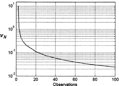
v(0, n, 1) are Gittins indices for the normal distribution with zero mean and unit variance, and have been previously tabulated [25]. Indices are stored in a lookup table and accessed in real time by the relay, which updates as new information becomes available. Fig. 2-3 shows Gittins indices v(0, n, 1), which decrease logarithmically with the number of observations.
---10 --- ---- --- ---... I ... ... --- . ... --- ::::::::: --- ---... ---... ---... ---...---... -- --- --- --- --- --- --- ---.. . . ---.. ---.. ---.. . . ---.. . ---.. ---.. . . ---.. . ---.. . . ---.. . . ---.. . . . ---.. . . . 10 --- ----: ---... ---... VN - --- --- --- --- --- --- --- --- --- --- ---10 --- ... --- ... ... - ---... ... ... ... .. ... --- ---... -... ... ... ... ... ... --- --- --- --- ---... --- ---... ---... -2 10 0 20 40 60 80 100 Observations
Figure 2-3: Gittins indices for Normal reward distribution with zero mean and unit variance.
Chapter 3
Field Implementation and
Experiments
We consider a one-way, two-link acoustic transmission in the Charles River Basin, Boston MA. A source modem located at the MIT Sailing Pavilion broadcasts a data message, which is repeated by the relay; an acoustic modem towed by a robotic surface vehicle. The destination node is a second robotic vehicle station-keeping 580m across the river from the source. A transmission is considered successful only if both hops succeed, i.e., the relay decodes the source packet, and the destination decodes the relay packet. Source transmissions may reach the destination directly; this through-transmission success rate reflects the performance of the acoustic channel with no relay. In setting up the adaptive positioning experiments, we assumed no prior knowledge of the acoustic channel beyond the usual spreading law. Nine candidate relay locations were chosen in a grid pattern centered on the line between the source and destination nodes (Fig. 3-1). In practice, such a choice would be influenced by mission constraints. For all experiments described, Site 1 was designated the starting location.
We describe two types of experiments, "autonomy" trials and "hybrid" trials. Autonomy trials were conducted with the Gittins index MAB algorithm and the adapted MABSC algorithm implemented as fully autonomous, turn-key elements in an autonomous multi-vehicle systems. Both acoustic acknowledgments, required by
Figure 3-1: Charles River Basin (Boston, MA) with Autonomous Surface Vehicle Nostromo inset. Relay locations are shown in white. Source and destination locations are shown in red.
fully underwater systems, and WiFi acknowledgments (for simplicity) were imple-mented. Hybrid trials were touring surveys that transmitted a set number of times at each point in turn, for the purposes of building a large dataset from which datapoints can be sampled offline.
3.1
Autonomous Surface Vehicles
All field experiments were conducted with custom-built autonomous surface vehicles
as the relay and destination nodes (Fig. 3-2). The source was a fixed station at the MIT Sailing Pavilion with a modem at the dock. Our autonomous surface vehicles tow acoustic modem transducers at a fixed depth to simulate underwater communications, with the benefits of GPS and WiFi connectivity for controlled experiments. Here, we describe the main components of the autonomous system, and further hardware and software details are presented in Appendix A.
Figure 3-2: Autonomous surface vehicle Nostromo (left) in Boston Harbor and with Silvana (right) on the Charles River.
3.1.1
Vehicle Hardware
The vehicles, built on small whitewater kayaks, are 1.8m (5.9ft) in length and weigh roughly 40kg (881bs). A bow-mounted trolling motor provides 220N (551bs) of thrust for a maximum speed of 3m/s (6 kts), making the kayaks easy to control and highly maneuverable. For the purposes of the experiments, the vehicles are commanded to travel a constant 1.5m/s and maintain a station-keeping circle ten meters in diameter on location. Two vehicles were used in field trials, as well as a fixed shore station
Icarus located at the MIT Sailing Pavilion.
3.1.2
MOOS-Based Software Architecture
MOOS (Mission Oriented Operating Suite) and MOOS-IvP software [8] are robotics
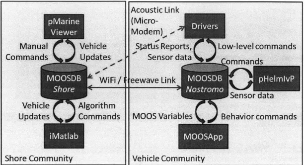
middleware packages developed by Paul Newman and Mike Benjamin to assist soft-ware development on robotic platforms. MOOS provides a basic message-passing and database service that allows multiple programs running on different platforms to share information in an organized manner, while MOOS-IvP adds applications specifically designed for the needs of marine vehicles. In particular, each vehicle maintains a per-sonal communications database called the MOOSDB. A MOOS process (MOOSApp) can publish data to this database, or subscribe for an update each time a variable is published, using asynchronous thread-based operations. In this way, communication between processes do not have to be handled individually.
Acoustic Link
(Micro-Figure 3-3: Illustration of MOOS and MOOS-IvP software architecture used for com-munications and control.
MOOSIvP's pHelmIvP is used as a "back-seat driver" on the vehicles, making high-level autonomy decisions based on pre-determined behaviors and communicating with low-level vehicle drivers. Multi-objective optimization is used to select a target course, speed and depth (if applicable) if there are competing behaviors active. For this application, we mainly implement the waypoint behavior and the station-keeping behavior. For the waypoint behavior, an x,y co-ordinate is commanded and a trackline is generated between its current and desired locations. In order to reduce crosstrack error, MOOS-IvP's trackline behavior then modulates the vehicle's desired heading so as to steer it towards a point on the trackline some lead distance ahead. The closer the vehicle is to the trackline, the further the lead distance is along the trackline. Station-keeping behavior turns off the vehicle's motor when it is within some inner radius, and allows the vehicle to drift beyond some outer slip radius before restarting the thruster. For all field experiments considered, the inner radius was three meters and the slip radius was ten meters. We implement open-source software library RTKLib (Real-Time Kinematic Library) [48] in conjunction with a GPS base station at the MIT Sailing Pavilion to achieve GPS noise covariance on the order of 10cm2
Onboard MOOSApps were implemented for the purpose of autonomy experiments. Gittins indices were computed offline and stored in a look-up table provided to the relay. Policy indices were computed on the shoreside computer with Matlab and communicated to the vehicles for simplicity; the computation itself could be handled in C++ with a slightly more powerful processor than the current single-core Gumstix onboard.
3.1.3
Acoustic Modems
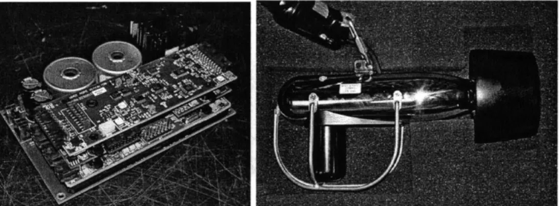
We use Woods Hole Oceanographic Institution (WHOI) Micro-modems [22], an es-tablished and commercially available technology for underwater acoustic data trans-mission (Fig. 3-4). The Micro-modem transmits at a fixed frequency (25kHz) and power (50W burst for variable duration dependent on packet type). NMEA 0183 mes-saging is used for commands and communication with the Micro-modem, and several transmission rates characterized by different error correction codes and modulation types are available.
Figure 3-4: Micro-modem Multi-Channel PSK Stack with Power Amplifier (left) and 25kHz Omnidirectional Transducer Towfish (right) Source: http://acomms.whoi. edu/umodem/
For the purpose of field experiments, quadrature phase-shift-keying (QPSK) rates 1 and 2 were used mainly for the reasonable tradeoff between packet success rate (in the range of 40% to 97%), packet data payload and time taken to transmit. Higher rates are characterized by larger packet payloads and correspondingly longer
transmission times and lower packet success rates (See Table B.2 in Appendix B). We note that programmable modem parameters such as packet encoding scheme can be included combinatorially as additional machines in the multi-armed bandit, but we have fixed these for simplicity. The Micro-modem reports various transmission statistics, and we present signal-to-noise ratios (SNR) from before the equalizer on the receiving modem ("SNR-In") as a representation of the physical channel quality. Statistics of other available measures (e.g. SNR out of the equalizer) are presented in Appendix A. A two-hop transmission as described above takes a minimum of fifteen
seconds with this hardware.
3.2
Autonomous MAB
For the MAB algorithm, a sample was designated as five transmissions so that the time required to sample once was comparable to the time of transit to another
lo-cation. All data transmissions were sent at phase-shift keying (PSK) Rate 2, with a fixed message size of 192 bytes. Estimates of the packet success mean and its vari-ance were initialized with a touring survey consisting of two samples at each location. This initialization was required as at least two observations are required to calculate a Normal Gittins index. Subsequently, the relay executed the algorithm, selecting the location with the highest index and breaking ties by favoring shorter travel dis-tances. Two experimental trials were conducted on the same day. Acknowledgments of transmission receipts were communicated from the destination to the relay over
WiFi for simplicity.
3.3
Autonomous MABSC
We employed the Bernoulli reward scheme with each sample consisting of a single two-hop transmission sent at PSK Rate 1. The MABSC algorithm was initialized with the assumption of 100% packet success probability at each site'. The
look-'Practically, the choice of initialization represents an acceptable performance threshold. Unex-plored sites may never be chosen if a previous site maintains performance above or equal to the
ahead horizon for policy enumeration was constrained to a maximum computation time of fifteen seconds. For a look-ahead horizon of five, the average computation time is on the order of one second2. For an underwater vehicle, learning the result of the relayed transmission (success or failure) from the destination robot must be done with acoustic acknowledgments. To simulate this with our surface vehicles, we utilized the Micro-Modem frequency-shift-keying (FSK) Mini-packet, a 13-bit message with robust performance. Our experiments have consistently shown packet loss rates of less than 5% for the FSK Mini-packet, thus it is substantially more reliable than the PSK 192-byte packets used for data transmission. If the acknowledgment is lost, the two-hop transmission is considered a failure by the relay. A touring survey consisting of a single circuit with ten transmissions at each site was performed before the experiment to provide a comparison measure, and the MABSC algorithm was run for the same mission time (55 minutes). Subsequently, the relay robot executed the
MABSC algorithm autonomously.
3.4
Hybrid Dataset Touring Surveys
In the field it is difficult to compare the performance of several competing algorithms as multiple relays would share the same physical space and channel, resulting in transmissions experiencing acoustic interference or extended wait times. Conducting experiments on different days is also undesirable as changing weather and surface conditions make it difficult to objectively evaluate the improvement in performance due to action by the algorithms. Thus, we construct a hybrid experiment; first, by collecting a large dataset of transmissions on a single experimental day. A touring survey taking five transmissions at every location was conducted for several hours. Then, each decision algorithm was applied to the same dataset, i.e. transmission re-sults were sampled from the dataset for the appropriate time and location and used to update the algorithm's information state. The shallow-water acoustic environment
threshold. Here we have prioritized exploration of all possible locations. 2
is in general difficult to model and using field data allows us to capture complex spatially-dependent behavior. The hybrid dataset contained 835 detected transmis-sions from source to relay and 636 detected transmistransmis-sions from relay to destination, with 493 of these being successfully decoded relayed transmissions.
Chapter 4
Acoustic Communications in
Shallow Water
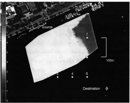
The transmission power of the Micro-modems is capable of transmitting many kilo-meters in the open ocean, however, in a shallow-water man-made environment like the Charles River, the performance of the channel is limited by multipath interference. Fig. 4-1 shows altimetry data revealing irregular bottom topography in the area vis-ited by the relay, especially a shallower shelf to the northeast. Though not visible, a deeper channel is also present towards the south (Boston) bank where the destination node is situated. Furthermore, there is a long stone wall about 10m behind the source node and a hard seawall on the opposite bank. The depth of the water in the Charles River basin is controlled by a series of locks at its mouth in Boston harbor. The MAB formulation is set up to adaptively explore these space-varying properties of the acoustic channel without sacrificing overall data transmission or requiring prior knowledge of the channel characteristics.
Fig. 4-3 shows SNR-In values reported for all acoustic transmissions during the MAB field experiment, Trial 2. The spread of values is -wide (25 to 25dB) and there is no clear spatial structure to the distribution. The closest locations for each respective link (Sites 1 and 5) do not have discernibly higher SNR-In values. Despite relatively high SNR-In values, the complex, shallow-water environment makes packet decoding difficult and introduces the spatial variation that the multi-armed bandit exploits.
![Figure 2-2: Gittins indices computed for a Bernoulli reward process (N=750, 0=0.95) A computational method for calculating indices for a Bernoulli reward process is described in Gittins [25]](https://thumb-eu.123doks.com/thumbv2/123doknet/14136196.469695/35.918.184.719.139.515/gittins-computed-bernoulli-computational-calculating-bernoulli-described-gittins.webp)