in Small, Slow-Burning Solid Rocket Motors
byJonathan R. Spirnak
B.S. in Mechanical Engineering with Honors United States Military Academy at West Point, 2016
SUBMITTED TO THE DEPARTMENT OF MECHANICAL ENGINEERING IN PARTIAL FULFILLMENT OF THE REQUIREMENTS FOR THE DEGREE OF
MASTER OF SCIENCE IN MECHANICAL ENGINEERING AT THE
MASSACHUSETTS INSTITUTE OF TECHNOLOGY JUNE 2018
Massachusetts Institute of Technology, 2018. All rights reserved.
Signature of Author:
_____Signature redacted
Jonathan R. Spirnak Department of Mechanical Engineering May 25, 2018
_Signature redacted
R. John Hansman, Jr. T. Wilson Professor of ronautics and Astronautics
V
.TW isunwrvisorSignature redacted
Certified by: Certified by:Signature
Accepted by: Douglas Hart Professor of Mechanical Engineeringred acted
Thesis SupervisorRohan Abeyaratne Chairman, De artment Committee on Graduate Theses MASSACHUSETTS INSTITUTE
MALCHA0 OLOGY
JUN 2
5
2018
LIBRARIES
Development, Modeling and Testing of Thermal Protection Systems
in Small, Slow-Burning Solid Rocket Motors
by Jonathan R. Spirnak
Submitted to the Department of Mechanical Engineering on May 25, 2018 in Partial Fulfillment of the Requirements for the Degree of Master of Science in
Mechanical Engineering
Abstract
Currently, a void exists in the development of small, unmanned aerial vehicles (UAVs) that can fly at speeds faster than 100 meters per second while maximizing endurance. Operating in such a regime requires the use of a slow-burning solid rocket motor. To achieve long burn times, an end-burning grain configuration is required in addition to a burn rate suppressant. Such a propulsion system presents unique thermal challenges due to the long exposure times and the close proximity of temperature sensitive vehicle components to the combustion reactions.
This thesis presents the development of a thermal management system appropriate for small, slow-burning solid rocket motors. Thermal protection is provided primarily by a thermally ablative liner with additional layers of fibrous insulation to protect the motor casing and avionics.
Due to the complex nature of thermochemical ablation and scarcity of previous research in slow, end-burning solid rockets, this problem is approached through both experimental and computational means. Experimental tests are performed on a full-scale model of an end-burning motor. Experimental results are used to validate a computational model of ablation. The ultimate goal is to provide an adequate amount of thermal insulation to protect the vehicle casing and avionics while maximizing propellant volume and hence endurance.
Building such thermal management schemes requires innovative materials and machining methods to incorporate thermal protection in a tight space. This thesis adds to the greater body of knowledge of thermal protection design in slow-burning solid rockets, especially as it applies to a new class of small, fast UAVs.
Thesis Supervisor: R. John Hansman, Jr.
Contents
Abstract ... 3
Nom enclature ... 7...7
Acronyms ... 7
Units of m easure ... 7
M athematical sym bols...7
1 Motivation: Thermal management of slow-burning solid rocket motors...10
1.1 Expanding the capabilities of slow-burning SRM s ... 10
1.2 Therm al problems for small, fast UAVs... 11
1.3 Thermal Protection System (TPS) overview... 17
1.4 Scope of docum ent ... 17
2 TPS design in slow-burning SRM s... 18
2.1 TPS design requirements ... 19
2.2 TPS m aterial recom mendation: ablative liner ... 21
2.3 TPS material recom m endation: fibrous insulation ... 22
2.4 M aterial thickness ... 22
2.5 Problem-solving approach ... 24
3 Physics and m odeling...25
3.1 Physics of ablation...25
3.2 M odeling ablation in a slow-burning SRM ... 26
3.3 Im pact of liner thickness... 34
4 Experim ental m otor testing ... 36
4.1 M otor design...37
4.2 Experim ental setup and instrumentation... 40
4.3 Experim ental testing ... 42
5 M odel validation ...-... 50
5.1 Data com parison ... 50
5.2 Sensitivity analysis...52
5.3 Liner thickness optim ization ... 54
5.4 Design recom mendations... 56
6 Conclusion...58
7 W orks Cited...59
A. Motivation for a small, fast UAV ... 61
B. Firefly overview...63
C. Calculation of internal combustion and external heat transfer coefficients...64
D. Cooling passage heat transfer estimates... 67
E. Motor preparation procedures ... 69
F. Deduction of propellant edge-burning problem in the test motor ... 77
Nomenclature
Acronyms
FEA - finite element analysis
PA - polymeric ablatives SRM- solid rocket motor
Ti-6A-4V- alloy of titanium, 6% aluminum, 4% vanadium by weight, ASTM B348, Grade 23 was used in this work
TPS -thermal protection system, divided into ablative (A-TPS) and non-ablative (NA-TPS) thermal protection systems
UAV- unmanned aerial vehicle
Units of measure
The standard abbreviations are used for the Syst&me international d'unitds (SI units) [1].
In some places, English Engineering Units are also provided to make the work more accessible to a US audience. They are abbreviated as:
ibm - pound mass Ibf- pound force in - inch
ft
- feetpsi - pound force per square inch ksi - 1000 pound force per square inch knot- nautical mile per hour
F- degrees Fahrenheit
Mathematical symbols
Units listed for each symbol. These units are assumed for each symbol unless otherwise specified. p - density [kg/s]
p - dynamic viscosity [Pa-si v - kinematic viscosity [m2/s] a - thermal diffusivity [m2/sJ
p
- volumetric expansion coefficient [1/K] a- - Stefan-Boltzmann constant [W/(m2-K4)] E - surface emissivity8 Front matter
y- ratio of specific heats A - area [m2
]
At - nozzle throat area [mm]
a - burn rate coefficient in Vieille's Law, units of [velocity x pressure-n]
CP - specific heat capacity at constant pressure [J/(kg-K)] C - total heat capacity [J/K]
c* - characteristic velocity [m/s]
dt - nozzle throat diameter [mm]
DH- hydraulic diameter [m]
F - thrust force [N]
h - specific enthalpy [J/kg]
htc - convective heat transfer coefficient [W/(m2
-K). The heat transfer coefficient is commonly expressed as h but is referred to as htc in this document to avoid confusion with specific enthalpy.
I - impulse [N-s]
Isp - specific impulse [s]
k - thermal conductivity [W/(m-K)]
K -- Ab/At - area ratio of burn to throat area in a solid rocket motor
m - mass [kg]
mn - mass flow rate [g/s]
M - Mach number
Nu - Nusselt number
n - burn rate exponent, Vielle's law
Pr - Prandtl number p - pressure [Pa]
pc - chamber pressure [MPa] q - heat flux [W/m2]
Q
- total heat transfer [W]Q*- effective heat of ablation [MJ/kg]
R -thermal resistance [K/WI Ra - Raleigh number Re - Reynolds number St -Stanton number T -temperature [K] T,- chamber temperature [K] t- time [s] t- thickness [mm] V - volume [m3]
V-
chamber volume [mm3] v - velocity [m/s]V - volumetric flow rate [m3/s]
Xa - local rate of ablation [mm/s]
1 Motivation: Thermal management of slow-burning solid rocket
motors
Recent interest in the development of a new class of small, fast UAVs has created a need for a low thrust, high endurance propulsion system. Advances in slow-burning solid rockets have made this technology suitable to propel small, fast UAVs. However, the unique characteristics of a slow-burning solid rocket motor (SRM) make it liable to thermal failure. Appropriate thermal protection techniques must be incorporated into the design of this motor to prevent the motor's casing from reaching temperatures that compromise its structural integrity and to keep the vehicle's avionics within a safe operating temperature.
1.1
Expanding the capabilities of slow-burning SRMs
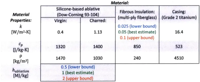
Currently, a void exists in aircraft that are able to fulfill missions requiring a small and fast aircraft. No aircraft smaller than 10 kg (22 lbm) are capable of flight faster than 100 m/s (170 knots). Vernacchia and Tao determined that a solid rocket motor (SRM) was the propulsion system most suitable to operate in this new flight regime.I By grouping together different classes of SRMs by their total impulse and burn time on logarithmic axes [Figure 1], the need to expand the capabilities of current solid rocket
propulsion technology to fit the mission requirements of small, fast UAVs is apparent. Appendix A presents an in-depth description of the motivation for the development of a small, fast UAV.
Solid Rocket Motor Categories
1E+10 Space Shuttle SRBs
1E+09
100000000
Missiles: Surface-to-Air,
S 10000000 Air-to-Air, Guided Upper Stage Motors
0. 1000000
STAR-24
E 100000
10000 Hobby Rocket Motors Small, Fast UAVs
1000
;
Aerotech J415W-L 100 10 1 1 10 100 1000Burn time [s]
Figure 1: Solid rocket motors categorized by their total impulse and burn time. Solid rocket propulsion systems required for
small, fast UAVsfall into an unexplored category. Data is taken from [2] [31 [4].
1 Matt Vernacchia and Tony Tao, Ph.D. candidates at The Massachusetts Institute of Technology, Department of
Aeronautics and Astronautics, originally conceived of the concept of a small, fast UAV. Vernacchia's thesis [5] presents a tradeoff study of different propulsive technologies that can fulfill the small, fast gap.
Five different categories of SRMs are provided to show where small, fast UAVs would fit in relation to existing classes:
Hobby Rocket Motors: At the low end of both the total impulse and burn rate spectrum are hobby rocket motors. These motors are categorized by their motor diameter, typically ranging from 18-98 mm. Motors in class J have a total impulse ranging from 640 - 1280 N-s, similar to what is required for small, fast UAVs. However, class J motors provide a burn rate of one to two orders of magnitude lower than. what is required for small, fast UAVs.
Upper Stage Motors: Upper stage motors on rockets commonly use solid rocket propellant and are usually tasked to accelerate payloads into higher energy orbits. Star-24 is an example of such a solid rocket motor used in an upper stage, able to provide 560 kN-s of thrust for nearly 30 seconds [3]. Missiles: The missiles that are used for military defense applications on combat aircraft and ground launch systems to provide air-to-air and surface-to-air attack capabilities are also powered by SRMs. Although their exact parameters are classified, they generally operate with total impulse levels
comparable to that of upper stage motors and a burn rate comparable to the higher end of many hobby rockets.
Space Shuttle Solid Rocket Boosters (SRBs): The Space Shuttle SRBs were the first solid rocket motors used as the primary propulsive system for human spaceflight. With a total impulse and burn time of 1.5 GN-s and 127 seconds, respectively, they are at the upper end of solid rocket design [4].
Small, Fast UAVs: In the bottom right corner of Figure 1 is the propulsive design space for small, fast UAVs. This void represents unexplored territory with solid rockets. A representative design point is shown in this space, requiring 1000 N-s of total impulse for a burn time of 2.5 minutes. To put that in perspective of current solid rocket propulsion technology, small, fast UAVs need a total impulse comparable to a class J hobby rocket and a burn rate on par with the Space Shuttle SRBs. As a result, designing a vehicle with a propulsive system in this space requires the development of a new class of SRMs that provide low thrust and high endurance.
1.2 Thermal problems for small, fast UAVs
A new type of slow-burning solid rocket propellant was developed by Vernacchia [5] to provide propulsion for small, fast UAVs. "Firefly"2
, depicted in Figure 2, is a representative example of a small fast UAV designed to use this type of slow-burning propellant.
2 "Firefly" is a transonic UAV currently under development at MIT Department of Aeronautics and Astronautics and Lincoln Laboratories. Firefly provides a representative example of a small, fast UAV and will therefore serve as the foundation for discussion throughout the rest of this work. A brief overview of the operating concept of Firefly is
Temperature Sensitive
Components on a Small, Fast UAV
Isometric view
Top payload Co in Vehicle casing Forward payloadRight
plane
section view
Payload area
10i mm
3-5 mm
Propellant
T
T
Burn direction
Nozzle
Figure 2: Temperature sensitive components, labeled in red, on "Firefly", an example of a small, fast UAV. Incorporating this propellant into a vehicle such as Firefly presents two challenges in thermal management unique to slow-burning SRMs. The first is that all vehicle components must be tightly integrated into the overall vehicle configuration. Consequentially, temperature sensitive components such as the motor casing and avionics are located on the order of millimeters away from the motor's hot combustion gases. The locations of these components in relation to the solid rocket propellant are shown in the right plane section view in Figure 2. Second is that to achieve a slow burn on the order of minutes, an end-burning grain configuration is used. The end-burning nature of the motor is shown in the right plane sectional view of Firefly. End-burning grains will cause vehicle components in the aft end to experience long exposure times to high heat fluxes from propellant combustion. Thus, incorporating slow-burning propellant into small, fast UAVs presents thermal challenges that must be solved to keep temperature sensitive components at safe operating temperatures for the duration of the mission.
ntrol surfaces with ernal servos
Nozzle
Control systems bay
Casing
___MMMMIF .- __
1.2.1 Compact vehicle configuration
For small, fast UAVs, the motor casing, avionics and control surfaces must be compactly integrated around the propulsion system to maintain an aerodynamic configuration. Unlike other SRMs where the avionics and servos are packaged in a separate section of the vehicle, these components are not afforded that luxury in small, fast UAVs.
An isometric view of Firefly (Figure 2) shows where the temperature sensitive components are located on the vehicle in relation to the solid rocket propellant. These include avionics stored in the front and top payload areas, servos and nozzle near the aft end, and a motor casing that surrounds the propellant. Since the propellant is end-burning, components near the aft end of the vehicle are subject to heat flux from propellant combustion for a longer duration compared to those at the fore. On the right plane section view of the UAV, the approximate distances of these components in relation to the propellant are labeled. Thermal protection can only be afforded about a centimeter of thickness in parts of the vehicle incorporating the avionics. Furthermore, the space between the propellant and motor casing is even smaller, in the range of 3-5 millimeters.
Table 1 elaborates on the components of a small, fast UAV most susceptible to thermal failure from propellant combustion. Components are described in terms of their maximum operating temperature, material composition, and exposure time to propellant combustion.
Table 1: Components of a small, fast UAV liable to thermalfailure.
Vehicle E xposure
Temperature limit [C] Material E Notes
Component time' [s]
Nozzle 2000-2500 Graphite, 150 Highest heat flux,
ceramic temperature, and exposure
foam, SiN4 times in the vehicle
Motor Casing During operation: Ti-6AI-4V6 10 (fore) Temperature limit depends
300-500' 150 (aft) on material type, casing
During gliding: wall thickness, and
1630-1650 (melting) chamber pressure
Servos7 60 [6] varies 150 Most vulnerable
(manufacturer electronics package due to
dependent) long exposure times
Payload8 125 [7] varies 0-100
3 Defined as the time after which the combustion flame front passes the section of interest.
4 Extensive work has been performed in the development of a nozzle for small, fast UAVs by Matt Vernacchia. The current design incorporates an inner graphite insert with high thermal and shock resistance surrounded by an insulating layer of ceramic foam that interfaces with the aft end of the motor casing.
s Values listed here are for the motor casing of the Firefly UAV.
6 Ti-6AI-4V was identified as the most appropriate material for the design of the UAVs motor casing. The motor casing under development at MIT is currently manufactured using additive manufacturing by Renishaw Inc. The values listed here are for this material.
7 The MKS DS65K servos have a range of -10 to 60 C (263 to 333 K.
8 Military electronics typically have an operating range of -55 - 125 C (218-398 K), however, avionics packages will vary depending on application.
Special care must be taken around the nozzle, aft casing area and control systems bay since these components will experience the longest exposure times to exhaust gases. In addition, the nozzle will experience heat fluxes roughly an order of magnitude higher than the rest of the vehicle, making the
nozzle and its surrounding casing especially vulnerable to failure from thermal loads.
The temperature limit of the motor casing must be set so the vehicle does not experience a structural failure either during operation when the motor casing is pressurized due to propellant combustion or after motor burnout. During motor operation, the temperature limit is a function of both the material type and the casing wall thickness. The temperature limit varies among casing designs because the material and geometry are subject to change. The Firefly UAV, for example, has a wall thickness that varies circumferentially from 1-4 mm. In thicker parts of the casing, an upper temperature limit is established in terms of the temperature at 50% yield tensile strength reduction (YTS) [8]. However, the temperature limit decreases in thinner-walled sections of the vehicle to account for increases in hoop stress. After burnout, the motor is no longer pressurized and the casing simply has to maintain its shape. Thus, the temperature limit is redefined in terms of the melting temperature.
Lastly, given that standard avionics have a maximum operating temperature on the order of 100 C, the vehicle's thermal protection must provide a significant temperature drop across its thickness to protect
both the motor casing and vehicle avionics.
1.2.2 Thermal problems of a long burn rate
Whereas most SRMs use an internally burning propellant grain configuration, small, fast UAVs must use an end-burning grain to burn two orders of magnitude slower than solid rockets of a comparable size. The difference between end-burning and internally burning grain configurations are shown in Figure 3.
Propellant Motor casing Nozzle
Cross-section End-burning
grain
Flame front Exposed surfaces
Internally ~ ~ ~ ~ ~ ~t burning grain. Propellant at ignition, t =0 t > 0 -- Exposed surface - - - - Flame front
Figure 3: Differences between end-burning and internally burning grain configurations for propellant contained within a motor casing. Surfaces exposed to propellant combustion are outlined in red and the direction of flame front progression is shown in
orange.
For internally-burning grains, a section of propellant is cored out from the center of the motor. Once the motor is ignited, it burns radially outward from its core. In end-burning grains, conversely, the aft section of the propellant is ignited and the burn front progresses along its cross-sectional area from the
aft to the fore of the vehicle. End-burning grains pose more thermal problems compared to internally burning grains for a number of reasons:
1. Greater exposure area: For internally burning motors, parts of the motor directly exposed to hot combustion flames are limited to the rocket nozzle since unburned propellant shields the motor casing from combustion gases. In end-burning grains, since the motor burns from the aft to the fore section of the vehicle, increasingly more of the motor casing is subject to exposure to the burning propellant. This effect is illustrated in Figure 3, showing differences in the progression of the flame front and exposure areas during a burn (t > 0).
2. Greater exposure time: Since the burn area for an internally burning grain is significantly larger than an end-burning grain, the burn rate is higher. To a first order, the burn rate scales linearly with the burn area according to Vielle's Law, which presents an empirical approximation of the burn rate r to the chamber pressure pc via two parameters:
r = a(Pcf
Where a and n are the burn rate coefficient and exponent, respectively, of a given propellant. These parameters are determined by combustion experiments on a given propellant formulation. The chamber pressure is directly proportional to the ratio of burn to throat area:9
Pc = Kpr(Pc)c*
Where p, is the solid propellant density, c* is the characteristic velocity of propellant combustion, and K is the ratio of burn to throat area:
Ab
K =
-A t
A smaller burn area translates to a lower chamber pressure and hence a lower burn rate. Thus, thermal protection in end-burning motors must be adapted to longer exposure times.
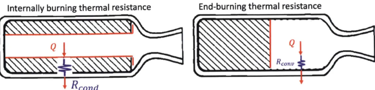
3. Decreased thermal resistance: Areas of unburned propellant for internally burning grains provide added thermal protection via conduction resistance to the surrounding motor casing. In an end-burning grain, after the flame front passes a section of the vehicle, the casing is left directly exposed to the combustion gases unless thermal protection is incorporated. Since these combustion gases flow through the casing, heat is transferred to exposed areas via convection. The differences in modes of heat
transfer are shown in Figure 4. Unburned propellant provides added conductive resistance to heat transfer from combustion in internally burning motors compared to a smaller amount of convective resistance in end-burning grains.
Internally burning thermal resistance
End-burning thermal resistance
Ft
K
I
Figure 4: Differences in thermal resistancefrom combustion heat transfer to the motor casing between internally burning and end-burning grain configurations.
4. Edge-burning: One of the main difficulties in an end-burning grain is keeping the burn area limited to the cross-section. A grain that is not well bonded to the surrounding casing or thermal insulation is vulnerable to de-lamination, thereby creating an edge-burning effect. When this occurs, the sides of the propellant grain burn in addition to the cross-section. An example of edge-burning is shown in Figure 5. If edge-burning occurs, the burn area and hence burn rate increase well above their designed values. An inhibitor, shown in green, is typically used to adhere the propellant to the thermal protection or casing and thus prevent edge-burning. Inhibitor design is covered in greater detail in Section 4.1 and Appendix E.
exposed
surfaces
Inhibitor
L..JS
Propellant
Flame front
- --Exposed surface
L---Thermal protection
Motor casing
Figure 5: An example of edge-burning in an end-burning motor. As the flame front creeps between the propellant and surrounding casing, the motor burns radially inward in addition to burning along its cross-section.
... ... .../Joo m
;
I
1.3
Thermal Protection System (TPS) overview
To overcome the unique thermal challenges posed by the propulsion system in small, fast UAVs, a robust thermal protection system (TPS) must be incorporated into the design of the UAV. The primary function of the TPS is to prevent the casing and avionics from reaching temperatures that endanger either its structural integrity or ability to complete mission requirements. The TPS also serves a number of secondary functions, including buffering the transmission of case strain to the propellant; sealing case, joints, and fittings; guiding combustion products into the nozzle; and inhibiting burning on propellant grain areas in which burning is undesirable [9]. Although much research and testing have been performed on TPSs in applications of spacecraft re-entry, missile launching systems, nozzle assembly and internal insulation for SRMs [10], no TPS has been adapted for use in slow-burning SRMs. 1.4 Scope of document
The new and unique mission of small, fast UAVs dictates the development of a slow-burning solid rocket motor. The unique hyperthermal environment and spatial constraints of this new class of UAVs require a thermal protection system specifically tailored for this application. This thesis will provide a means to design such a TPS using a combination of computational and experimental methods.
Chapter 2 presents an overview of the design of slow-burning SRMs given its unique hyperthermal environment. The physics and physical modeling of the motor are covered in chapter 3. The
experimental design and testing of a slow-burning motor are explained in chapter 4. An analysis of the validity of a computational model using experimental data is reported in chapter 5.
2 TPS design in slow-burning SRMs
The design of an aircraft's TPS encompasses both material selection and thickness. Multiple materials may be used in the design of a TPS if each material provides a different means of resistance to heat transfer. The material type and thickness are dependent on the severity of the internal and external environment and the duration of exposure. Since these factors vary widely among aircraft, a TPS must be tailored to a specific aircraft configuration and its mission requirements. An insufficient amount of thermal protection will result in the thermal failure of an aircraft component. However, using too much thermal protection increases the inert mass and volume of the aircraft, decreasing the aircraft's capacity to carry additional propellant or payload.
The concept of integrating a TPS into a slow-burning SRM is shown in Figure 6. To get the motor to burn at a slow rate, the propellant must be end-burning and fit inside a motor casing with a long aspect ratio. An appropriate amount of thermal protection must fit in between the casing and the propellant to cool the motor casing for the duration of the flight. An inhibitor is applied between the propellant and thermal protection to keep the two strongly bonded together and prevent edge burning.
The motor geometry shown here is a simple cylinder with a high aspect ratio. In reality, the motor design for small, fast UAVs will be more aerodynamic in shape with dimensions that enable it to achieve desired thrust and endurance levels.
Fore end Aft end
L
--- Nozzle
D
IPropellant
Burn direction External airflow
Combustion flow
t(x) Thermal protection
Motor casing External airflow
Figure 6: Concept of a generic slow-burning SRM. Thermal protection, shown in dark gray, fits compactly into the motor casing and surrounds the propellant.
Thermal protection, shown in dark gray, is directly exposed to hot combustion gases internally. The heat flux into the thermal protection is dependent on the combustion temperature and velocity of exhaust products among a number of other factors. For end-burning motors, areas near the aft portion of the motor near the nozzle will receive higher heat transfer due to longer exposure times to propellant combustion compared to those at the fore. Thus, the thickness, t(x), of thermal protection may vary over the length of the motor. The thermal protection interfaces with the motor casing which is cooled by external airflow. The degree of cooling is dependent on the flight speed and altitude.
The goal of the thermal protection is to prevent heat from propellant combustion from increasing the temperature of the motor casing and vehicle avionics beyond their temperature limits. For the internal
thermal protection liner in solid rocket motors, this is typically accomplished through two means. The first is incorporating materials that undergo endothermic decomposition reactions, absorbing energy through a latent heat of ablation instead of transferring it into the motor casing. This is illustrated in the diagram by part of the red heat flux arrow being directed into the thermal protection material. Second, parts of the thermal protection that do not decompose should have a low thermal conductivity to provide additional resistance to heat transfer. Sometimes, multiple materials are incorporated into the design of a TPS to provide thermal protection through different means.
This chapter presents guidelines to design a TPS for a slow-burning SRM. First, design requirements for this application of a TPS are listed to serve as a guide to selecting TPS materials. Next, a-brief overview of TPS materials are presented with a recommendation of the materials most appropriate for slow-burning SRMs. Ultimately, a silicone-based thermally ablative material surrounded by a layer of fibrous
insulation is recommended as the type of thermal protection best suited for this application. Lastly, the problem of optimizing the design of a TPS for this new class of motors is framed. This entails choosing the thicknesses of thermal ablative and fibrous insulation. This problem motivates the need to conduct computational and experimental analyses of these materials in a slow-burning SRM to optimize the thickness of each.
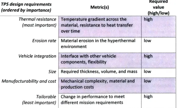
2.1 TPS design requirements
To better understand the materials required for incorporating thermal protection into a slow-burning SRM, a list of TPS design requirements were made. Table 2 outlines the design requirements for a TPS in slow-burning rocket motors. These requirements, listed by their order of importance, will serve as a guide for choosing TPS materials best suited for slow-burning SRMs.
Table 2: Thermal protection system design objectivesfor slow burning solid rocket motors as it applies to small, fast UAVs. Requirements are listed in order of importance, from most to least important.
TPS design requirements Required
(ordered by importance) (high/low)
Thermal resistance Temperature gradient across the high
(most important) material, resistance to heat transfer over time
Erosion rate
Vehicle integration
Size Manufacturability and cost
Tailorable (least important)
Material erosion in the hyperthermal low environment
Interface with other vehicle high
components, flexibility
Required thickness, volume, and mass low Mechanical complexity, material and low production costs
Change in performance to meet high
Thermal resistance: Because the TPS will interface with hot propellant gases on one side and vehicle components on the other, it must provide a sharp temperature gradient for the full mission duration to prevent thermal failure of vehicle components. The Firefly UAV, for example, requires a TPS capable of providing around a 1500 K temperature drop across spaces ranging from 5-10 mm for a 2.5-minute burn time.10
Erosion rate: Because end-burning motors have a relatively small burn area compared to internally burning ones, the nozzle throat must be small to keep the motor operating at the designed chamber pressure. Small nozzle throats put the motor at risk of nozzle clogging from the debris of combustion products. A low erosion rate of the TPS is necessary to minimize the amount of debris from the TPS material. In addition, a low erosion rate means increased char retention within the material. This is favorable from a heat transfer perspective because the charred material can continue to absorb heat instead of transferring through the material and into the casing. Thus, a low erosion rate also helps the TPS meet the thermal resistance requirement.
Vehicle Integration: Integrating the TPS into the vehicle should impose little restrictions on the vehicle's shape and aerodynamics. The TPS should serve additional roles such as sealing other mechanical components, providing structural support and mitigating case strain on the propellant.
Size: Having compact thermal protection means it occupies minimal space and contributes little to the inert mass of the vehicle while still providing adequate thermal protection to vehicle components. This maximizes available mass and volume to carry additional propellant or payload.
Manufacturability and cost: The means used to manufacture the TPS should be simple and scalable to reduce manufacturing time. This ensures the TPS can be easily evaluated by experimental means before full-scale production. The equipment used to manufacture a TPS should ideally be limited to that found
in common university machine shops. In addition, TPS materials should be commercially available and cost-effective.
Tailorable: Assuming small, fast UAVs will fly in a variety of missions, a TPS must be adaptable to mission requirements. UAVs, for example, will experience different external cooling depending on the external temperature, velocity during flight, and total flight time. In addition, avionics will have different maximum operating temperatures. A tailorable TPS means the thickness of the materials used can be easily adjusted to provide adequate thermal protection while maximizing propellant carrying capacity in a wide range of operating environments. Furthermore, the TPS must be scaled according to its exposure time and temperature sensitivity of the vehicle components it must protect. Hence, more thermal protection is required at the aft end of the motor because of longer exposure times and the need to keep servos from overheating.
The design requirements for slow-burning SRMs motivate the need to incorporate an ablative material surrounded by a layer of fibrous insulation as the vehicle's primary thermal protection mechanisms. These materials are explained in greater detail in the following sections.
0 Firefly's required temperature difference is based on an estimation of the combustion gas temperature performed using Rocket Propulsion Analysis (RPA) software.
2.2 TPS material recommendation: ablative liner
TPS materials are broadly classified as Ablative (A-TPS) or Non-Ablative (NA-TPS). The material choice depends on the severity of the hyperthermal environment in which they are exposed. The severity of a hyperthermal environment is a function of the heat flux and exposure time a material experiences with respect to its environment. In addition, many TPS materials found in rocket nozzles and internal SRM insulations are subject to large shear stresses due to particle impingement from combustion products. NA-TPS are those which after exposure to a given hyperthermal environment, experience no change in mass or material properties [10]. They are generally limited to mild to moderate hyperthermal
environments, such as on heat shields of reentry vehicles, and are designed to ensure reusability for a set number of missions. Common NA-TPS materials include ceramics and certain metals such as tungsten or rhenium.
A-TPS, conversely, are used in severe thermal and chemical environments such as those found lining an SRM chamber or nozzle. Ablation is a complex thermochemical process, providing a means of cooling through a combination of surface melting, sublimation, charring, evaporation, decomposition in depth, and film cooling [11]. In aircraft, A-TPS provide a sacrificial method of heat protection and are therefore typically limited to a single use [12]. The detailed processes governing ablative heat transfer in slow-burning SRMs are discussed in section 3.1. A-TPS are recommended over NA-TPS for applications of thermal protection for slow-burning SRMs because they are capable of providing a large temperature drop over a small thickness. The thermal resistance of ablatives through endothermic decomposition reactions is more effective than only conductive resistance offered by non-ablatives. In addition, NA-TPS are often more rigid and more difficult to manufacture compared to A-TPS.
Within the broad range of A-TPS materials, Polymeric Ablatives (PAs) are the type most suitable for use in the extreme thermal environment found inside a slow-burning SRM. PAs consist of a polymer matrix, usually silicone or phenolic based, that undergoes charring as a result of exposure to a hyperthermal environment. For the internal insulation of slow-burning SRMs, silicone-based ablatives are favored over phenolic-based because silicone's superior flexibility enables the material to conform to the motor casing, acting as a gasket by preventing any exhaust leaks around mating faces and joints. Silicone-based ablatives, therefore, best meet the requirement of vehicle integration. To meet erosion resistance requirements, silicone-based ablatives are embedded with carbon fibers and other fillers to prevent the charred matrix from shearing off from particles in the combustion products impinging on the ablative material surface. Silicone-based ablatives are easily manufactured and are tailorable because they can be cast into the different complex geometries necessary for aerodynamic bodies. The one drawback is that the material is only effective for a single use because of the material decomposition that occurs.
However, since ablatives are relatively low cost and easy to manufacture, the reusability requirement is of secondary importance compared to all others.
The silicone-based ablative material chosen for this study is a Dow Corning (DC) 93-104 material. This material provides excellent performance in the high heat flux, high shear environment found in the internal environment of a solid rocket motor. It incorporates carbon fibers into the silicone matrix for increased char retention as well as silicon-carbide spheres that reduce the material's density and promote greater heat sinking.
2.3 TPS material recommendation: fibrous insulation
Since ablative materials primarily provide thermal protection through endothermic decomposition reactions, a layer of fibrous insulation is incorporated around the ablative material to better meet the requirement of thermal resistance. The typical thermal conductivity of silicone-based ablatives is in the range of 0.2-0.5 W/m-K. Fibrous insulation, on the other hand, has thermal conductivity values an order of magnitude lower. Multi-ply fiberglass is the recommended type of fibrous insulation to incorporate around an ablative liner for applications of thermal protection within slow-burning SRMs. The thermal conductivity of multi-ply fiberglass is in the range of 0.04 - 0.06 W/m-K.11 Multi-ply fiberglass also comes
in thin layers, on the order of 0.1 mm, that can be wrapped around the ablative material, making this insulation easy to integrate with the rest of the vehicle while taking up minimal thickness. The number of wraps of fiberglass around the vehicle can be varied depending on the available space and amount of thermal resistance required.
2.4 Material thickness
Assuming that an ablative material like DC 93-104 surrounded by multi-ply fiberglass insulation make up the TPS for slow-burning SRMs, it is necessary to determine the appropriate thickness of each material.
As was previously mentioned, the thickness of thermal protection materials must be optimized for a particular application. For the particular case of slow-burning SRMs, this problem entails choosing the thickness of a thermal ablative and fibrous insulation to adequately protect the motor casing and
avionics from thermal failure while minimizing the thickness of each material incorporated between the propellant and motor casing. Minimizing thickness of TPS materials is desirable because both the amount of propellant and TPS are constrained by the motor casing geometry. Thus, a thinner TPS increases the amount of propellant that can fit inside the motor casing.
1 These values were experimentally measured at ambient conditions. Since pressures in the internal environment of an SRM are higher, this will decrease the density of the fiberglass and increase the effective thermal
The integration of the chosen TPS materials, each with a given thickness, into a slow-burning SRM is illustrated in Figure 7.
Inhibitor
t (x) Silicone-based
J()ablative liner
t<o tfa Fiberglass
Motor Casing Nozzle
time
burnout
-Burn direction
Figure 7: Operating concept of integrating thermal protection into a slow-burning SRM. The thickness of ablative liner and fibrous insulation must be optimized for this application to prevent vehicle components from overheating due to propellant
combustion.
Before firing (Figure 7 a), layers of thermal ablative and fiberglass, each with a given thickness, t1and tfg
insulate the motor casing from propellant combustion. During firing (Figure 7 b), the ablative material chars as a function of exposure time to propellant. For end-burning motors, this results in greater charring near the aft end of the vehicle compared to the fore. As a result, ablative liner thickness should vary across the length of the vehicle, hence t, = t, (x). At burnout (Figure 7 c), the char front will have penetrated a certain distance into the ablative material. Thus, the total thickness of the ablative can be broken down into a charred component and virgin component: ti = tchar + tvirgin.
Ideally, the motor should be designed so that the maximum amount of liner chars throughout the burn without fully charring through the ablative liner. The reason to minimize the thickness of the virgin ablative liner at burnout is twofold. First, since the liner is significantly denser than the surrounding fiberglass insulation, using the least amount of liner reduces the inert mass of the vehicle. Second, the liner provides thermal protection primarily by decomposition reactions that result when exposed to hot combustion gases. Thermal protection by conduction resistance of the virgin material has a second order effect. Since the thermal conductivity of fiberglass is an order of magnitude smaller than that of the virgin liner, the thickness of the fiberglass should be maximized as opposed to the virgin liner to provide maximum resistance to heat transfer via conduction. Some virgin material, however, still needs to remain at the end of the fire to prevent burn through and continue to seal joints around the motor casing. If no virgin material remains, the TPS's primary protection mechanism of thermochemical ablation no longer exists. This is problematic because high temperature and pressure combustion gases are directly exposed to the weak fiberglass insulation layer. This will spike the casing temperature and allow for an alternative exhaust flow path, resulting in leakage.
2.5
Problem-solving approach
The remainder of this document addresses how to choose the thickness of ablative material and fibrous insulation for thermal protection in slow-burning SRMs. First, a computational model of ablation for end-burning motors is derived. This model has a number of unknowns, such as heat flux, ablation temperature, char rate, and heat of ablation. The best estimates of these parameters are made with available information from previous literature and experimentation. The model outputs the required insulator thickness required to keep the motor casing below its temperature limit defined previously in Table 1. Preliminary model results give an estimate of the required ablative liner thickness in a given environment thermal environment. This model is explained in greater detail in section 3.2.
Once the required thickness is estimated, experimental motor testing is conducted. These tests are necessary because end-burning grains in slow-burning SRMs are difficult to model and not well studied and thus require some means of experimental validation. Motor tests are conducted with varying liner thicknesses of thermal protection materials. The motor is instrumented to measure the casing
temperature at different locations during the burn. Post-fire, the liner is dissected and the char thickness is measured at various radial and axial positions. The thrust and chamber pressure are also
monitored during the burn.
The experimental results are then used to inform parameters for the computational model in addition to providing surface temperature and char depth measurements to validate the model. Once validated, the model is used to predict required insulator thickness under a wide range of operating conditions not determined feasibly by experimentation alone. Firefly, for example, is designed to fly at Mach 0.8 at an altitude of 20-30 kft. Experimentation does not take into account added external cooling since
experimental tests are conducted under ambient conditions while attached to a thrust stand. The model, however, can predict how varying flight conditions, motor geometries, and propellant formulations affect the required thermal liner thickness.
Firefly's motor geometry is used as a guide when designing a TPS for slow-burning SRMs. Although modeling and experimentation are performed on this specific vehicle configuration, the validated model input parameters can be modified to reflect different vehicle configurations and operating
environments. Thus, this model can serve as a guide in designing the thermal protection materials for a wide range of SRMs.
3
Physics and modeling
This chapter presents the physics and modeling of ablation in slow-burning SRMs. First, the underlying physics of ablation are outlined to include all major heat transfer processes. A computational model is then created based on the underlying physics. In this model, the transient one-dimensional heat equation is solved numerically on a discreet 1D spatial grid. The details of this model are explained as well as the underlying assumptions. Given the complex nature of thermochemical ablation, this model does not account for all the detailed mechanisms governing the heat transfer in ablating slow-burning SRMs. The shortcomings of a pure modeling approach to the problem motivate the need to validate the model against experimental data presented in Chapter 4.
3.1
Physics of ablation
Although ablation can occur for a wide range of materials depending on their exposure to a given hyperthermal environment, this section will focus on the mechanisms governing ablation in polymeric ablatives, specifically silicone-based ablatives, given their application to slow-burning SRMs. The heat transfer mechanisms governing ablation in silicone-based ablatives are detailed in Figure 8.
Combustion gas flow
Radiative & convective Boundary layers (momentum, Particle heat transfer thermal & concentration) impingement
Ablating surface Surface shear Pyrolysis outgassing
Ch..
*d er...0**0.**..."'...
N
Surface recession
4
Char layer
.ae altie_ Decom osition zon
Char : Fibergles: : : : direction Motor casing Layers of ablation s abltive
Before ablation During ablation
Figure 8: Ablative heat transfer mechanisms for a silicone-based polymeric ablator. Schematics are shown before and during ablation. These mechanisms are present for ablators serving as thermal protection in slow-burning SRMs. Flow from hot combustion gases transfers heat via convection and radiation to the surface of the ablating material. The Firefly motor, for example, has a combustion gas temperature that can vary from 1600-2300 K depending on the chamber pressure and propellant formulation. As the gas flows, thermal and momentum boundary layers develop above the surface. When combustion begins, the virgin material absorbs heat, resulting in a change in temperature. When the temperature reaches its ablating or charring temperature, material decomposition occurs. Since ablation is a complex process involving multiple phase changes, ablation occurs over a range of temperatures with multiple instances of material decomposition. Although Figure 8 is a simplification of the entire ablation process in which the decomposition of the virgin ablative material takes place in defined layers, it is useful for understanding the underlying mechanisms governing heat transfer in charring ablatives. The layers of ablation are:
TPS materials
for slow-burning SRMS
Ablating surface: Multiple thermochemical processes take place at the surface of the ablator. Impingement from particles embedded within the combustion gases results in a shear force at the surface, assisting in material erosion. For some polymers, this surface may expand as a result of material expansion from decomposition and the collection of debris from combustion gases, or recede due to material erosion.
Char layer: Since the char layer is directly exposed to combustion gas flow, it undergoes the most significant degradation and weight loss. It consists of cracked layers of mostly black carbon. Without the aid of reinforcement fibers, significant sloughing can occur due to high shear stresses from particle impingement in the thermal environment.
Decomposition zone: This zone is actively undergoing pyrolysis through endothermic processes. Reaction products formed here penetrate through the char layer, outgassing into the boundary and providing a film cooling effect by thickening the thermal and momentum boundary layers. Since ablation is a complex process with multiple phase changes occurring over a range of temperatures, this zone contains all of the thermochemical processes that take place as a material decomposes. As time increases, decomposition progresses further into the surface of the vehicle.
Virgin silicone-based ablative: This layer is not heated enough to experience any change in composition. Heat transferred into this layer is either absorbed into the material or passed to the surrounding motor casing. An effective silicone-based ablative minimizes the amount of heat transferred through this layer to keep the motor casing below its temperature limit.
3.2 Modeling ablation in a slow-burning SRM
A general starting point for modeling heat transfer in a TPS is to solve the one-dimensional heat conduction equation for TPS materials and its surrounding structure while heated on one side from combustion gases. Because this model does not account for thermal decomposition reactions that most ablative materials are designed to encounter, this model is accurate only for materials that experience very small heat fluxes up to 1-2 W/cm2
[10]. Since the thermal environment within a slow-burning SRM will result in material decomposition, this method is not appropriate.
For more severe thermal environments, the detailed processes of thermochemical ablation must be taken into account. At the simple end of ablative modeling, the complex thermal decomposition processes can be lumped together using a single parameter, the heat of ablation. Doing so assumes all ablative processes take place at a single temperature. Before reaching this temperature, the material is in its virgin state. Once it reaches this temperature, the temperature will remain constant until enough heat, equivalent to the heat of ablation, changes the material from a virgin to a charred/decomposed state.
When designing thermal protection for a new class of slow-burning SRMs, a model must sufficiently account for material decomposition from combustion gases at temperatures on the order of 2000 K in addition to a flame front that progresses from the aft to the fore end of the motor. This model must also be flexible enough to rapidly change parameters as the motor geometry or flight conditions change. Since this model is validated by experimental data, the number of parameters within the model must be
minimized to determine which parameters have the greatest effect on the overall temperature response.
3.2.1 Ablative heat transfer model
The purpose of preliminary modeling of thermal ablation is to get an estimate of the required thickness of TPS materials to adequately protect temperature sensitive vehicle components. A preliminary model of ablation was first developed by Vernacchia [5]. The transient 1D heat equation was solved
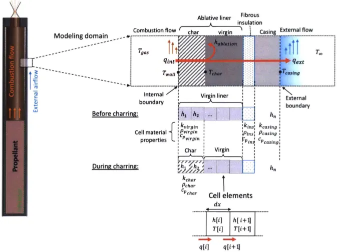
numerically on a discreet 1D grid. Changes in variables across time and spatial domains are accounted for. An overview of the model for a slow-burning SRM is shown in Figure 9.
28 Co Modeling domain Before charring: Ce During charring:
Ablative liner Fibrous insulation
mbustion flow char Vn ;Casing External flow
gas
Ii
;: hablaion tlTwaji y Tchar iTcasing
Internal Virg n liner
boundary
h2
f
kvirgin kinsl1 material SPvirgin :Pins:
properties Pvirgin
Char Virgin
kchar Pchar
CPchar Cell elements
dx External boundary hn kcasing Pcasing cPcasing h[i] h[ i+4 T ij T i+4 q[iJ q[i+1
Figure 9: Overview of a ID model of thermal ablation for a slow-burning SRM.
The modeling domain is broken up into layers, consisting of the ablative liner, fibrous insulation, and vehicle casing, each with their own set of material properties. The ablative liner is further broken down into its charred and virgin states depending on the temperature at its present state. When the
temperature of the virgin liner reaches the charring temperature, the virgin material properties change to those of the char. The layers are discretized into n spatial points, with each cell, i, of length dx. The surfaces of the ablative liner and motor casing make up the internal and external boundaries,
respectively, of the modeling domain.
Convective boundary conditions are applied at the internal and external boundaries. The internal boundary characterizes the heat transfer from the combustion gas into the ablative liner. The heat transferred in the internal boundary, qint, is a function of the internal heat transfer coefficient, htcint,
and the temperature difference between the combustion gas, Tgas, and ablative wall, Twall. A portion of the heat transferred from the combustion gas goes into decomposing the ablative liner. This is shown in
Figure 9 by a red arrow that curves away from the straight portion at the interface between the charred and virgin material. The heat that goes into decomposing the liner is quantified by the enthalpy of ablation, hablation. Ablation occurs at the charring temperature, Tchar. Heat from combustion that does
boundary. The external heat transfer, qext, is a function of the external heat transfer coefficient, htCext,
and temperature difference between the motor casing, Tcasing, and the environment, T. These temperatures are labeled at their respective locations in Figure 9.
Fourier's Law and the 1st Law for a control volume (CV) are used to derive the specific form of the ID
heat equation used in this model. Fourier's Law in 1D:
-kaT
ax
The 1st law for a control volume for a solid substance (no changes in kinetic and potential energy), is
expressed as:
aph a4
at
ax
Where the ph is the specific internal energy, e,.
These equations cannot be simplified further because the material properties (k, p, cp) change as the material undergoes ablation.
The specific enthalpy, h, is the state variable tracked throughout the ablation process. At a given time, h
expressed as a vector is: h
h 1
h
h
2 ... n-~x
ht is then updated for every time step using forward Euler:
ht -> ht4
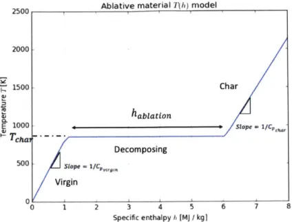
The temperature at each time step is tracked as a function of enthalpy. For a given time:
h ; T < Tchar CPvirgin T(h) = TIar; T = Tchar h -;T > Tchar C Pchar
The T(h) curve is dependent on the charring temperature, enthalpy of ablation, and the specific heats of the virgin and charred liners. An example of the T(h) curve is shown in Figure 10 for a given char temperature, heat of ablation, and specific heat values for charred and virgin material.
2500 Ablative material 7Th) model 2000 k 1500 -Char hablation E 1000- Slope .1/ch STchmc ~ Decomposing 500
/
,,7e Virgin 0 1 2 3 4 5 6 7 8Specific enthalpy h IMJ / kg]
Figure 10: An example T(h) curvefor the ablation model. The shape of the curve depends on the charring temperature, heat of ablation, and specific heat constants for the charred and virgin liner.
The net heat flux is then computed using Fourier's Law:
4t
= -k
-f
Ox
For the internal and external boundaries, the heat flux is calculated by:
qint = htcint(Tgas - Twaii)
qext = htcext(Tcasing - Too)
Where htc is the convective heat transfer coefficient at each boundary. Next, the derivative of enthalpy with respect to time is calculated:
Oh 1Oq
Ot p at
Finally, the enthalpy is updated using forward Euler:
-
h
ht = ht +- (At)
The model makes the following simplifying assumptions:
1. Heat transfer is one-dimensional, limited to the wall-normal direction.
2. Charring erosion and swelling are ignored. For some classes of polymeric ablatives, this phenomenon is well documented in severe thermal environments of SRMs [10] [13]. Since the temperature and pressure of combustion gases in Firefly's motor are less severe than other SRMs, these effects are assumed negligible.
3. Material ablation is broken down into only two zones: a charring zone and the virgin material. The transition from virgin liner to charred material is captured by a single parameter, the heat of ablation
(hablation). This phase change occurs at a single charring temperature,
Tchar-4. Heat transfer from the combustion gas to the liner is due solely to convective heat transfer. Making this assumption neglects the other forms of heat transfer present during ablation at the internal boundary, including pyrolysis outgassing and heat transfer due to radiation and particle impingement from the combustion products into the ablative liner.
3.2.2 Model parameters
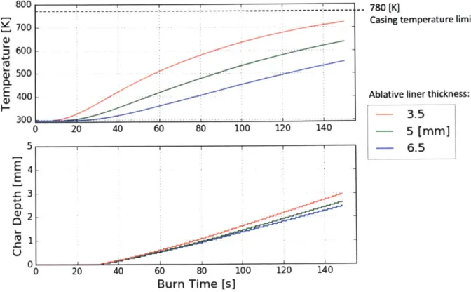
This model is capable of providing two outputs useful to assess the performance of a thermal protection design in a slow-burning SRM. First, it tracks the temperature of the surface of the motor casing as a function of burn time. This is useful to ensure that a given TPS design and motor geometry keeps the casing under its temperature limit. The motor should remain under this temperature for the duration of the burn. Second, it should record the liner char depth as a function of exposure time to combustion gases. Monitoring char depth reveals whether or not the ablative will char through during operation. The accuracy of the model outputs depends on the accuracy of the input parameters. The model input parameters come from two sources: material properties and boundary conditions. The following subsections list the parameters associated with each source as well as the model input value. Where there is a large uncertainty for a parameter, three values are listed. These values correspond to a best estimate of the value, colored in green, as well as the lower and upper bounds, colored in blue and red,
respectively. Justifications for the value of each input parameter are provided. 3.2.2.1 Material properties
The material properties of interest in this model are the thermal conductivity, k, heat capacity, cp,
density p, and heat of ablation for the ablative material, hablation. Table 3 displays the material property
32
Table 3: Material properties of model inputs. Material: Material Properties: k [W/M2-K] cp [J/kg-K] [kg/M3]
Silicone-based ablative Fibrous Insulation: Casing:
(Dow-Corning 93-104) multi-ply fiberglass) (Grade 2 titanium)
Virgin: Charred: 0.025 (lower bound) 0.4 1.13 0.05 (best estimate) 16.4 0.1 (upper bound) 1320 1400 850 523 1470 1030 240 4510 0.5 (lower bound)
habladon 1 (best estimate)
2(upper bound)
Silicone-based ablative: Material properties of the virgin silicone-based ablative liner are well characterized, listed by the manufacturer in [14] and measured experimentally over a temperature range of 300-500 K in [15]. These properties display a negligible amount of variation across the
measured temperature range and therefore are assumed constant. The material properties for the char of this specific silicone-based ablative were also evaluated in [15] over a temperature range of 360-1920 K. Values listed in the table were evaluated at the material's charring temperature of 800 K.
This model lumps the complex mechanisms of ablation together into an enthalpy of ablation, hablation, that occurs at a single charring temperature. In reality, ablation happens over a wide range of
temperatures since the ablative is a composite material with various different fillers that decompose at different temperatures. For the purposes of this model, the char temperature was taken to be that of silicone's. The charring temperature for silicone is well known and is estimated to be Tcha, = 800 K [10] [16].
There are large uncertainties in estimating the enthalpy of ablation because no reference values exist and it is difficult to estimate by experimentation. Estimating hablation is done by defining an effective heat of ablation, Q* [9] [17]:
hablation * = q
Xa P
The heat flux is found through Newton's Law of cooling. For an internal rocket environment, this is calculated as: qint = htcint (Tgas - Twaii), where Tgas is the combustion gas temperature and Twati is the wall temperature, approximated as the material's charring temperature. The best estimate of the convection coefficient, htcint, is used. The local ablation rate, xa is found from previous experimental tests [18]. Previous subscale motor testing of a silicone ablative liner is explained in section 3.5 of Vernacchia's thesis [5]. For a specific test, the silicone liner in a subscale motor formed 0.25 mm of char
in 7 s of burn at 0.5 MPa. p is the density of the thermally ablative material. Using this method, the enthalpy of ablation was estimated to be: hablation = 1 MJ/kg. Because of the uncertainties in the value
of htcint explained in the next section, the lower and upper bounds vary from the best estimate by a factor of two.
Fibrous insulation: Multi-ply fiberglass cloth was used as the specific type of insulation. Under ambient conditions, its properties are well known. Reported values for c, and p are the average of those values for air and fiberglass. There is an uncertainty in estimating the thermal conductivity of fiberglass. kfg was measured experimentally to be 0.05 W/m-K in ambient conditions. The high chamber pressures during motor operation, however, could compress this fibrous insulation layer, thereby reducing its effective thermal conductivity. The effect of this behavior is estimated to increase its experimentally measured thermal conductivity by a factor of two. The experimentally measured value could also be an overestimate of the material's thermal conductivity. The lower bound of kjg is lower by a factor of two. This value is near the absolute lower limit of any insulation in ambient conditions based on the thermal conductivity of air (kair = 0.024 W/m-K).
Casing: properties of the titanium casing materials are well known and are nearly independent of temperature [19].
3.2.2.2 Boundary conditions
The heat transfer at the model's internal and external boundaries depends on the convective heat transfer coefficient and the fluid's temperature [Table 4].
Table 4: Boundary properties of model inputs.
Boundary Location: Boundary
Properties:
htc [W/m2
-K] (heat transfer coefficient)
T [K]
(internal: Tas external: T,.)
Internal (combustion gas to liner): The combustion gas temperature was estimated using Rocket
Propulsion Analysis (RPA) software. Nusselt correlations are used to estimate the value of the convective heat transfer coefficient from the combustion gas into the ablative liner, htcint- Uncertainty in
calculating htcint using Nusselt correlations arises because these correlations only predict convective heat transfer for well-characterized flows, i.e. turbulent or laminar and fully-developed. Other factors to consider are film-cooling from pyrolysis outgassing, mass transfer into or out of the boundary by
combustion products or by material erosion, surface roughness effects from soot buildup on the
chamber walls, and internal radiation. The internal convection coefficient was calculated using a Nusselt correlation that assumes turbulent, fully-developed flow. These calculations are provided in Appendix C. Turbulent flow is assumed for the best guess because the charred surface is rough and the Reynolds Number of the flow is nearly twice the critical Reynolds Number for internal flows. Based on these correlations, htcint= 80 W/m2
-K. The uncertainty in this value is estimated to be +40 W/m2
-K. The lower bound represents a condition where the flow is laminar and film-cooling effects from pyrolysis
outgassing thicken the thermal boundary layer, thereby decreasing htc1nt. The upper bound assumes
Internal: External:
(combustion gas to ablative liner) (motor casing to surroundings) 40 (lower bound)
80 (best estimate) 24
120 (upper bound)