Chemistry Department, University of Fribourg
Master Thesis
SYNTHESIS AND COMPUTATIONAL STUDY OF NEW GEODESIC POLYARENES DESIGNED FOR MOLECULAR HYDROGEN STORAGE AND INVESTIGATION OF THE
DAKIN-WEST REACTION MECHANISM
Nathalie Joset
Supervisor Prof. Dr. Titus A. Jenny
i Abstract
This work presents the synthesis of a new geodesic polyarene molecule based on corannulene’s motive and especially designed for hydrogen storage. Indeed such curved systems are bearing a dipole moment which can polarize H2 molecules resulting in their adsorption. The complexation of our target
molecules with alkali ions would increase their dipole moment as well as the interstitial volume between the molecular stacks thus increasing the hydrogen storage capabilities.
In the first part, DFT calculations were undertaken to compare our target molecule with other curved systems and to point out the advantages or inconvenients for hydrogen storage applications.
Two main synthetic pathways were postulated, the first one starting from 2,6-difluoroacetic acid and the other starting from 2,6-dichlorophenylacetic acid. In the first it was planned that the cyclized target molecule would be obtained by fluorhydric acid elimination which was a recently discovered means of curvature introduction; the second would result of flash vacuum pyrolysis or palladium catalyzed reaction which are already well known for such purposes.
Unfortunately problems were encountered at the first step in each pathway, namely during the bisbenzyl ketone synthesis. The Dakin-West reaction was initially explored, but it proved to be inefficient and because its mechanism was not well understood, computational calculations supported by ESI-MS measurements were undertaken. Bisbenzyl anhydride was identified as intermediate, thus it was tested as a starting reagent treated with 4-dimethylaminopyridine but without success except when starting from unsubstituted 2-phenylacetic anhydride. For each pathway Claisen condensation was tested and offered the desired bisbenzyl ketone from the corresponding ester, but only in poor yields. A third approach in which 2-(2,6-dichlorophenyl)acetyl chloride was reacted with a Grignard reagent formed from 2-(bromomethyl)-1,3-dichlorobenzene and magnesium was tested. Unfortunately Wurtz coupling between brominated species was mainly observed thus hindering the production of bisbenzyl ketone as major product.
ii
Acknowledgments
This work was achieved in the scope of the Master thesis under the supervision of Prof. Titus A. Jenny at the Department of Chemistry, University of Fribourg (Switzerland).
I would especially thank…
… Prof. Titus Jenny for accepting me in his research group and for sharing his valuable knowledge and passion with me.
… Prof. Thomas Bally for his acceptance as expert for this Master Thesis and for the numerous advices and help during my studies.
… my family, Carole, Suzy and Laurent for their support during all my studies.
… Sofia Martin Caba for her friendship and for accepting me in her laboratory.
… every colleagues with whom I shared beautiful moments.
iii
Contents
1 INTRODUCTION ... 1
1.1 Hydrogen fuel cells ... 1
1.2 Hydrogen storage ... 2
1.3 Geodesic polyarenes ... 5
1.4 Brief overview of bowl-shaped molecules synthesis ... 7
1.5 Aim of the present work ... 13
2 RESULTS AND DISCUSSION ... 15
2.1 Computational calculations for geodesic polyarenes ... 15
2.2 First strategy starting from 2,6-difluorophenylacetic acid ... 19
2.2.1 Dakin-West reaction ... 19
2.2.2 Ketonic decarboxylation... 21
2.2.3 Claisen condensation ... 21
2.3 Second strategy starting from 2,6-dichlorophenylacetic acid ... 23
2.3.1 Dakin-West reaction ... 24
2.3.2 Investigations on Dakin-West mechanism ... 26
2.3.2.1 Postulated mechanism based on ESI-MS analysis ... 26
2.3.2.2 Computational calculations on the Dakin West reaction intermediates ... 28
2.3.3 Anhydride pathway ... 40
2.3.4 Claisen condensation ... 42
2.3.5 Grignard reaction ... 43
3 CONCLUSION AND OUTLOOK ... 46
4 EXPERIMENTAL PART ... 49
4.1 General considerations ... 49
4.2 First pathway starting from 2,6-difluorophenylacetic acid ... 49
4.2.1 Synthesis of ethyl 2-(2,6-dichlorophenyl)acetate : ... 49
4.2.2 Synthesis of 1,3-bis(2,6-difluorophenyl)propan-2-one: ... 50
iv
4.3.1 Synthesis of 1,3-diphenylpropan-2-one: ... 50
4.3.2 Synthesis of 2-phenylacetic anhydride: ... 51
4.3.3 Synthesis of 2-(2,6-dichlorophenyl)acetic anhydride:... 51
4.3.4 Synthesis of 1,3-diphenylpropan-2-one: ... 52
4.3.5 Synthesis of ethyl 2-(2,6-dichlorophenyl)acetate : ... 52
4.3.6 Synthesis of 1,3-bis(2,6-dichlorophenyl)propan-2-one: ... 53
4.3.7 Synthesis of 2-(2,6-dichlorophenyl)acetyl chloride: ... 54
v Abbreviations
Cy Cyclohexane
DCC N,N‘-Dicyclohexylcarbodiimide
DCM Dichloromethane
DFT Density Functional Theory
DIPEA N, N-diisopropylethylamine
DMAP 4-Dimethylaminopyridine
Eq Equivalent
ESI-MS Electospray ionization mass spectrometry
Et3N Triethylamine
EtOH Ethanol
Exp. Experimental
FVP Flash vacuum pyrolysis
GC Gaz chromatography
HOMO Highest occupied molecular orbital
IR Infra-red
LDA Lithium diisopropylamine
LUMO Lowest unoccupied molecular orbital
MeCN Acetonitrile
MIM 1-Methylimidazole
MS Mass spectrometry
MWNT Multiwalled nanotube
NMR Nuclear magnetic resonance
PAH Polyaromatic hydrocarbon
PEM Polymer electrolyte membrane or Proton exchange membrane
Ppm Part per million
vi
Rxn Reaction
Sat. Saturated
THF Tetrahydrofurane
UPLC Ultra-high Pressure Liquid Chromatography
1
1 INTRODUCTION
1.1 Hydrogen fuel cells
Many efforts to reduce greenhouse gas emissions and the dependence on finite non-renewable fuel resources have led to the development of a variety of alternative energy solutions. Of specific interest is the hydrogen fuel cell, which converts the chemical energy of hydrogen into electricity through chemical reaction with oxygen. Such devices are different from traditional batteries in that they require a constant source of hydrogen and oxygen to run, but an advantage is their continual electricity production as long as these inputs are supplied. There are many types of fuel cells, mainly differing by the electrolyte they use. Hereafter is represented a schematic diagram of cell configuration of a polymer electrolyte membrane (PEM) fuel cell also known as proton exchange membrane fuel cell (Figure 1). 1
At the heart of a PEM fuel cell is a polymer membrane that acts as electrolyte which is impermeable to gases but which conducts protons (hence the name proton exchange membrane). The membrane is squeezed between the two porous electrodes typically made of carbon. At the interface between the porous electrode and the polymer membrane is a layer of catalysts particles, typically platinum supported on carbon where electrochemical reactions occur. Molecular hydrogen feeding the anode side is oxydized producing protons and electrons. The protons travel through the membrane, whereas the electrons are driven through an external circuit producing direct current electricity. Electrons come back at the cathode side where they meet the protons that went through the membrane and oxygen that
2
is fed on the cathode where reduction occurs. Water is created in the electrochemical reaction and then pushed out of the cell with excess flow of oxygen. This reaction in a single fuel cell produces only about 0.7 V. 2 To get this voltage up to a reasonable level, many separate fuel cells must be combined to form a fuel-cell stack. If the fuel cell is powered with pure hydrogen, it has the potential to be up to 80 % efficient. However, we still need to convert this electrical energy into mechanical work by means of an electric motor and inverter. The efficiency of this motor/inverter is about 80 %, giving an overall efficiency of about 64 %.2
Applications of fuel cells can be categorized in two main applications: stationary and transportation. Stationary fuel cells can be used for backup power in commercial, industrial or residential builings where they are mostly used combining heat produced by fuel cells and power production. Transportation fuel cells can be used for vehicles, including automobiles, buses, forklifts, airplanes, boats, and submarines. The global fuel cell market which was $650 millions in 2010 will be at $1.6 billion in the year 2016 promising a beautiful future. 3
1.2 Hydrogen storage
Although stationary applications are already commercialized since 2008, the market of transportation fuel cells is less developed, especially due to difficulties in hydrogen storage, including cost, reversibility and the storage mass and volumetric densities. 4 Indeed, liquid hydrogen has a very high energy content by weight (142 MJ/kg) compared to gasoline (47 MJ/kg) 5, but a very low energy content by volume (10 MJ/L) compared to gasoline (35 MJ/L) 6. This makes hydrogen storage particulary difficult due to the size and weight constraints of a vehicle. The following sections introduce four major technologies being currently used or actively studied for hydrogen storage.
Compressed gas
A light-duty fuel cell vehicle will carry approximately 4-10 kg of hydrogen on board to allow a driving range of more than 300 miles, which is generally regarded as the minimum for widespread public acceptance. 7 To satisfy such conditions, traditional compressed hydrogen gaz tanks would require more space than the trunk of typical automobile. Moreover, even if recent developments proved that fibre-reinforced resin can sustain pressures up to 700 bar, high pressure hydrogen storage is not a suitable storage means due to safety concerns and poor volumetric densities. 8
Liquefaction
Liquefied hydrogen is denser than gaseous hydrogen and thus contains more energy for a given volume; by this means, it can be stored on board the vehicle, as has been demonstrated by BMW with their production-ready Hydrogen 7 vehicle collection. 9 But the major drawback is that cryogenic methods require the input of relatively large amounts of energy for maintaining a liquid at 20 K for long periods. Moreover, there is inevitably a boil-off rate which is currently in the range of l%/day. 7
3
Tank insulation is required to decrease hydrogen loss but this would add weight, volume and cost of such a dispositive, restricting its range of applications.
Solid-state hydride storage
Solid-state hydride storage in which hydrogen is chemisorbed via chemical bonds, offers several benefits over previously presented techniques. They operate at low pressure as compared to compressed hydrogen, and don’t need to be kept at cryogenic temperatures as required for liquid hydrogen storage. Hereafter several different hydrogen storage means are compared according to their volumetric hydrogen densities (Figure 2). 10
In the following sections, three main metal hydride classes were summarized taken from a review about metastable metal hydrides for hydrogen storage written by Graetz et al. 10
Metal hydrides and complex hydrides
Complex metal hydrides which store atomic hydrogen through a chemical bond are often categorized by their reversibility or their ability to be rehydrogenated under moderate temperature and pressure conditions. One representative of this class is sodium aluminium hydride (NaAlH4) which can release
4 wt % of hydrogen at temperatures around 160°C during catalyzed (typically 2-4 mol% Ti) thermal decomposition, thus approaching the U.S. Department of Energy (U.S. DOE) targets of 6.5 % gravimetric hydrogen density and 62 kg/m3 volume at ambient temperature. Most importantly, the dehydrogenated material (NaH + Al) can be rehydrogenated under moderate conditions; but systems based on this kind of material (Na2LiAlH6, KAlH4, K3AlH6, etc.) have an inherent heat problem posing
significant engineering challenges for onboard refueling. Indeed, a large hydrogenation enthalpy
Figure 2: Volumetric hydrogen density (gH/L) of different hydrogen storage methods including compressed gas,
physisorption in a metal organic framework (MOF), liquid hydrogen (LH2), ammonia, methane and a variety of metal and complex hydrides. These values are only for the storage medium and do not take into acoount the full system volume (e. g., tank and fuel cell)
4
(typically greater than 33 kJ/mol H2) is necessary to offset the large entropy change (110 – 130 J/Kmol
H2) during the hydrogenation process. Based on a generic reversible hydride with a slightly positive
free energy (so that H2 is released at pressures above 1 atm) and a 5 kg H2 tank, roughly 83 MJ of heat
is released during hydrogenation. The major drawback is that if the refueling process has to be done in 3 minutes (1.67 kg H2/min), those 83 MJ of heat would need to be dissipated at a rate of 0.5 MJ per
second which remains a big engineering challenge.
Chemical hydrides
Chemical hydrides offer high capacity and fast hydrogen desorption rates at low temperature. However these are not directly reversible under moderate hydrogenation conditions and typically require off-board chemical regeneration. From such typical materials (NaBH4), molecular hydrogen is
typically generated through a low temperature hydrolysis reaction (Eq. 1):
+ 2 → + 4 (Eq. 1) In this type of system, a large amount of hydrogen can be generated at rapid rates that easily meet the U.S. DOE fuel flow rate target 0.02 gs-1kW-1 but after hydrolysis the reactants are left in deep thermodynamic minimums making the refueling process economically and energetically costly. Moreover, water should be readily available restricting the range of application to aquatic applications (submarines).
Ammonia borane (NH3BH3), which represents a class of compounds that can release hydrogen at fast
rates through a low temperature thermolysis reaction, can store nearly 20 wt % of hydrogen! But its major drawback is that during the decomposition, NH3 or B2H6 can be produced and even small
amounts of such byproducts can destroy the proton exchange membrane of the fuel cell.
Metastable metal hydrides
Aluminium-based metastable hydrides, namely AlH3, LiAlH4, Mg(AlH4)2 and others, offer high
capacities and low temperature hydrogen release; during decomposition, they can’t form species which will damage the fuel cell membrane and additionally, those materials exhibit a low decomposition enthalpy, which reduces the heat required to release hydrogen at practical pressures.
This very promising technology is particularly suited for portable power systems, but is not ideal for automotive applications especially because of the high cost for regeneration.
5 Adsorption in carbon nanostructures
Carbon structures as single and multiwalled nanotubes (MWNTs) 11, nanofibers 12, activated carbon, fullerenes 13 and geodesic polyarenes (Figure 3) have an enormous potential in hydrogen storage technologies, especially for onboard vehicle storage.
Their major advantages are their high volumetric and gravimetric densities. However, there is a serious drawback. On the one hand, the ease of adsorbing and desorbing H2 at ambient temperatures is
limited because physisorption energies are too low (typically < 10 kJ/mol H2). On the other hand,
chemisorption energies are too high (typically > 10 kJ/mol H2). 10
Indeed, physisorption is a process where the adsorption of hydrogen molecules is due to van der Waals attractive forces between carbon and hydrogen whereas in chemisorption, hydrogen molecules are covalently bonded to the carbon atoms. Each carbon atom in geodesic polyarenes is sp2 hybridized and bonded with three other carbon atoms. Due to the dangling π-bond, there can be at most one hydrogen atom stored per carbon atom. The maximum storage is larger than in the physisorption process, but the major drawback is that desorption of hydrogen atoms requires higher temperature. 14 It should also be taken into account that the storage system would be capable of being recharged at the filling station in a few minutes. Thus, physisorption is thought to be the most interesting process for onboard storage.
1.3 Geodesic polyarenes
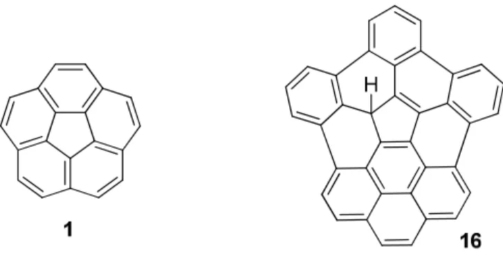
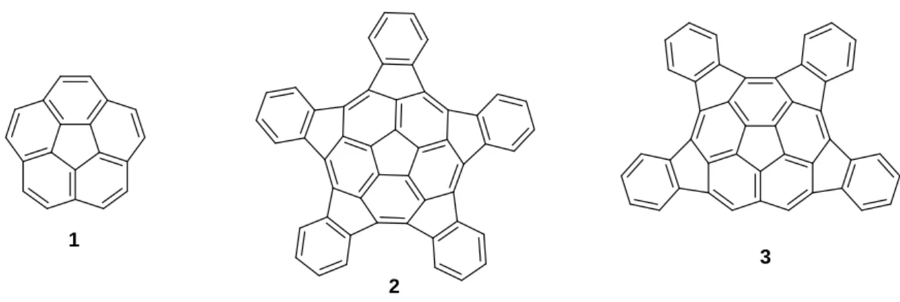
This latter class of potential hydrogen storing material and specifically geodesic polyarenes is the interest of the present work. Many kinds of bowl-shaped molecules like corannulene 1 (C20H10)
pentaindecorannulene 2 (C50H20) and tetraindecorannulene 3 (C44H18) have been computationally
studied 15 and show that such structures are really good candidates for hydrogen storage (Figure 4).
6
1
2
3
Indeed, they are characterized by curved π systems composed of pyramidalized carbon atoms (Figure 5) 16 and one of their particularities is that they bear a permanent electrical dipole moment able to induce a dipole moment on H2 molecules resulting in their adsorption.
Hydrogen uptake of 1 was experimentally measured and found to be 1.5 wt. % at 77 K and 45 bar 17 and 0.8 % at 298 K and 72 bar. 18 These values are significantly lower than those required by the U.S. DOE, but the latter conditions should be more practicable. Using DFT calculations, Scanlon et al. first found that corannulene dimers arranged in a sandwich (local minimum) or T-shape (global minimum) geometry. They then run molecular dynamical simulations with hydrogen molecules by keeping fixed the adsorbent molecules in their initial positions. Interlayer distance (ILD) and intermolecular distance (IMD) where calculated at the B3LYP/6-311G(d,p) level (Figure 6). Molecular dynamics calculations showed that as the ILD increases from 4.8 to 8.0 Å, the weight percent of hydrogen uptake increases to values equal to or greater than 2 wt % of hydrogen at 300 K and at pressures of 46 to 139 bar.
This suggests that increasing the ILD should be a solution for better hydrogen uptake. A mean of doing this is the introduction of alkali metals between corannulene units. Chen et al. have found that insertion of potassium or lithium in carbon nanotubes leads to the absorption of 14 resp. 20 wt. % of
Figure 4: Corannulene 1, pentaindecorannulene 2 and tetraindecorannulene 3 structures
Figure 5: Planar π system (left) and pyramidalized carbon (right)
7
hydrogen at 653 K and room temperatures! 19 Alkali doped corannulene monomers have been studied computationally by Banerjee et al. at the B3LYP/6-31G(d,p) level and they came to the conclusion that K+ and Na+ doped corannulenes can adsorb six hydrogen molecules each at the surface of the alkali. This can be attributed to the charged-induced polarization of the H2 bond (Figure 7).
20
A third case has been studied by Simonyan et al. by molecular simulations, namely hydrogen adsorption in charged singlewalled carbon nanotubes. They concluded that charged nanotubes lead to an increase of 10 – 20 % at room temperature in relative to the uncharged tubes adsorption. Because of the positive quadrupole moment of hydrogen, negatively charged nanotubes are preferable. 21
Therefore the synthesis of negatively charged curved hydrocarbon systems is a valuable alternative. The mono and dianion of 1 complexed with sodium and potassium ions in the presence of [18]crown-6 ether were synthesized by Zabula and coworkers but were not tested for their hydrogen storage capabilities. 22 Crown ether additives would probably be inappropriate, increasing considerably the weight of such materials.
1.4 Brief overview of bowl-shaped molecules synthesis
Hereafter are presented synthetic methods used for curved systems preparation. Corannulene 1 was one of the first bowl-shaped molecules which has been thoroughly studied. An efficient synthetic pathway in three steps was designed by Scott et al. in 1997 with an overall yield of 20 – 25 % where ring closing of chlorinated precursor was achieved via flash vacuum pyrolysis (FVP) (Scheme 1). 23
8
In 2002, they used the FVP technique to synthesize diindenochrysen 6 in 25 – 30 % overall yield starting with fluoranthene 4. This time, the precursor for the ring closing step was brominated 5. They found that starting with the parent hydride instead of the bromine substituted 5 dropped the yield to 0.6 % (Scheme 2). 24
Siegel et al. developed a procedure for the synthesis of 1 at kilogram scale 25 giving the opportunity of using it as starting material for the synthesis of other geodesic polyarenes. Thus, Scott L.T. et al. developed a new strategy for the synthesis of a highly curved 8 starting from 1 (Scheme 3). 26
Scheme 1: Corannulene 1 synthesis by Scott et al. in three steps
9 Negishi coupling 52 % DCM ~ 40 % FV P 1100 °C /0.25 torr 2 - 3 % Cl I Cl Cl Cl Cl Cl Cl Cl ZnCl Cl Cl Cl ClCl Cl Cl Cl Cl Cl 1 8 7
Mizyed et al. showed that the chlorination of 1 with iodine monochloride gave 7 as the major product with only a minor amount of tetrachloro derivatives. 27 Even if the last step shows only 2 – 3 % yield after chromatography, it proves that FVP is a useful tool for the introduction of curvature. Indeed, they believe that at such temperatures, the C-Cl bond rupture produces reactive aryl radicals. The high temperatures also provide the energy required to temporarily distort the intermediate species away from their equilibrium geometries, thereby bringing the transient aryl radical centers into bonding distance with otherwise remote atoms in the molecule. Thermodynamically, such reactions will be dominated by the gain in entropy resulting from the loss of 10 chlorine atoms and 10 hydrogen atoms at high temperatures. 27
As an alternative for the harsh conditions of FVP and to get better yields, Jackson et al. reported palladium-catalyzed C-C coupling reactions for the preparation of compound 2 (Scheme 4) and tetraindenocorannulene 3 using microwave heating. 28
10
The procedure follows the work of Wang et al. for the synthesis of indacenopicene derivatives 9a and
9b. The only difference was the use of microwave instead of traditional heating. Those
palladium-catalyzed reactions gave in general better yields 15 and 35 % for 2 resp. 3 and even 70 – 90 % for less curved 9a and 9b derivatives (Scheme 5). 29
In a recent research, Amsharov and coworkers 30,31 proved that C-C bond formation would be achieved by means of HF elimination using γ-Al2O3 (Figure 8).
Scheme 4: Synthesis of 2 using palladium-catalyzed ring closing method
11
Advantages of such an approach are the low atomic size of fluorine atoms favoring their introduction in sterically constrained cove regions and the high chemical resistance of the C-F bond which extends the scope of reactions that can be applied for precursor synthesis. 26 Moreover, the reaction conditions are really milder than those used in FVP. Indeed, γ-Al2O3 is activated by annealing at 500 °C for
15 min at 10-3 mbar pressure then mixed with the fluorinated compound and finally heated to 150 – 200 °C for achieving condensation in high yields (Scheme 6). These good results can be attributed to the concerted mechanism in which bond formation and rupture occur at the same time thus no reactive intermediates which might cause side reactions would be formed. The driving force of the reaction is the strong Al-F bond formation (Figure 8).
F F
γ
−Al2O3 99 % F F F Fγ
−Al2O3 98 % 9c 10However, even if fluorinated compounds seem to be good precursors for introducing curvature, their potency to prepare highly strained systems was unsuccessful so far and needs to be further explored. 32 Nicolas Fragnière claimed having synthesized curved polyaromatic hydrocarbon 11 by achieving cyclodehydrogenation of a cyclopentadiene derivative using the Scholl reaction but only the partially oxidized bis-phenanthrene 12 was isolated (Scheme 7). 33
Figure 8: Possible mechanism of the cove-region closure process for benzo[c]phenanthrene condensation showing
coordination on the aluminium oxide surface, aromatic transition state, and Al-F bond formation
12 H H AlCl3/CuCl2 H CS2, r.t , 5 min 25 % 11 12
Starting from reagents already containing links between aromatics had been thought to favor further cyclisation. Thus, a strategy starting from pyrene quinone was developed by Pierric Weber (Scheme 8). 34 Unfortunately, due to rearrangements, cyclopentadiene derivative 15a was only obtained in 18 % yield and no oxidation conditions were tested.
Ph O Ph Ph O Ph MeOH, 82 % 1. PhLi 2. MeOH 3. LiAlH4/THF Ph Ph Ph 14a 15a H KOH O O Toluene, 18 % Not tested 16 H 13a
Scheme 7: Oxidation attempts of pentaphenyl cyclopentadiene derivative to give PAH 11
13
The first aim of the following work was the application of ring closure via HF elimination, FVP or palladium catalysis on precursors synthesized following the procedure developed by Fragnière and Weber.
1.5 Aim of the present work
In this work, new strategies were developed for the synthesis of geodesic polyarene 16 which would be a material of choice for hydrogen storage due to its increased diameter as compared to 1 (Figure 9). Indeed, this will rise the number of interacting sites and the interlayer distance due to the higher curvature. This diameter increase could also change a bit the curvature resulting in a probable slightly higher dipole moment value which would favor hydrogen adsorption.
If 16 would not show acceptable hydrogen storage capacities, it is believed that it could react with alkali hydrides (NaH or KH) producing alkali-curved polyarene complexes 16’K or 16’Na displaying even higher dipole moments giving rise to stronger interactions with hydrogen molecules (Scheme 9).
Banerjee and coworkers have performed DFT calculations to find the hydrogen uptake capacity of an isolated alkali-doped corannulene molecule. They have found that hydrogen molecules bind at the surface of alkali metal preferentially. 20 This approach is interesting, albeit not really realistic, because it may be far from real solid state systems.
Figure 9: Corannulene 1 and first target molecule 16
14
A more realistic aspect would be that alkali-cations could act as spacer, increasing the ILD and thus the hydrogen uptake. However, those cations would also occupy some space, thus hindering hydrogen adsorption at their location. Furthermore, it should also be kept in mind that alkali insertion will raise the weight of 16’K and 16’Na significantly.
Dipole moments of different curved molecules were calculated and compared with our target molecules using DFT. The distances between curved polyarenes and alkali ions were also measured to see which of 16’K or 16’Na will be better suited as subunit spacer.
15
2 RESULTS AND DISCUSSION
2.1 Computational calculations for geodesic polyarenes
In order to visualize the electrostatic potential surface and dipole moment of coronene 17, corannulene
1, highly curved 8, target molecule 16 and alkali-doped complexes 16’K and 16’Na, computational
calculations were performed in the gas phase using the hybrid exchange correlation energy functional commonly known as B3LYP 35 , implemented in the Gaussian 09 software. 36 After each geometry optimization at the B3LYP/6-311G* level, vibrational frequency calculations were achieved at the same level of theory to ensure that the molecular system was at a local minimum and to provide the thermodynamic correction factors at 298 K. Electrostatic potential surfaces were computed by running B3LYP/6-31G* single point energy calculations on Spartan ‘10 software 37 starting from optimized structures.
Dipole moments were obtained by single point energy calculations at the B3LYP/6-311++G(d,p) level on optimized structures. It’s important to notice that it’s not the purpose of the present work to accurately determine the dipolar moments; however, it’s expected that it would give a qualitative comparison between the different polyaromatic hydrocarbons (PAHs).
17
1
In Figure 10, two different PAHs are presented, namely coronene 17, which is totally planar and curved corannulene 1. Schematic illustration of the qualitative quadrupole moment of coronene is also represented. 38 In the case of 17, all the “micro” dipoles between atoms cancel as a consequence of molecular symmetry. When curvature is introduced, the two-dimensional “micro”-dipoles still
Figure 10: Calculated dipole moments (also experimental value for 1) and electrostatic potential surface of planar 17 and
curved 1. The regions of most negative electrostatic potential are shaded red and the most positive regions are shaded blue. Schematic qualitative quadrupole represented for coronene 17
µ1 = 2.17 D (exp.: 2.07 D) µ17 = 0 D x y z x y x z x y x z
16
annihilate each other but 3-dimensional ones appear. The consequence is that all the z-components are added resulting in a permanent electric dipole moment. The B3LYP method was found to be quite accurate as the difference between calculated and experimental dipole moments 18 of corannulene was only 0.1 Debye.
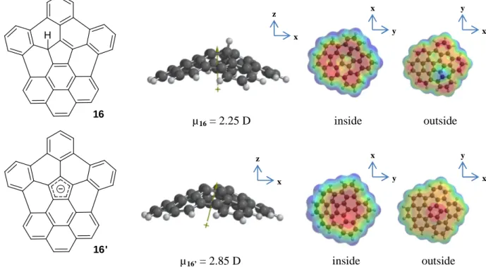
In Figure 11 calculations at same level were realized for 16 and the deprotonated form 16’. The latter allowed us to see qualitatively that concave face was more electron-rich, thus favoring the interaction with alkali cations on this side. This observation was quite surprising from a classical point of view because if electrons are only considered as negative charges, there would be a higher repulsion between them inside than outside of the bowl molecule.
16 H
16'
Single point energy calculations at the B3LYP/6-311++G(d,p) level and thermal corrections from B3LYP/6-311G* frequency calculations where used to compare the energy difference between concave and convex bonding of the alkali ion in 16’K and 16’Na complexes. To do this, the following equations were used.
∆ ! "#$$ !% & '( ! "#$$ '( ! )*+! "#$$ )*+!%
∆, , ! & , '( ! , )*+!% (Eq.2)
∆- ! ∆ & .∆,
Where E(cmpx), E(PAH) and E(ion) are the total energies of complexes 16’K or 16’Na, polyarene 16’ and alkali ion. ∆Hf, ∆S and ∆Gf are the formation enthalpies, entropies and free Gibbs energies.
Energy differences were determined by using Eq. 3.
Figure 11: Calculated dipole moments and electrostatic potential surface of 16 and its deprotonated form 16’
µ16 = 2.25 D x y x z µ16’ = 2.85 D x z y x x y y x inside outside inside outside
17
∆-"#/0 ∆- ! & ∆- ! (Eq.3) Where ∆Gconv is the Gibbs free energy difference between concave, ∆Gf(cc) and convex, ∆Gf(cx)
forms. For either 16’K or 16’Na, the concave complex was found to be favored with a ∆Gconv of -23.2
resp. -9.5 kJ/mol. This observation is quite different than those obtained by Banerjee et al. for corannulene alkali doped molecules. 20 Indeed, they found that the most stable sodium complex would be the convex form while those of potassium complex would adopt a concave arrangement. However they computed dipole – ion interactions of neutral corranulene with cations, while we have considered ion-ion interactions between anion 16’ and cations. Moreover, the differences between convex and concave structures are low and Mizyed et al. have elsewhere noticed that theoretical calculations give different answers for predicting which of the two π-faces is more electron rich. Indeed, they found that semi-empirical calculations give a more negative electrostatic potential on the convex surface of corannulene while higher density functional calculations predict exactly the opposite properties. Until now, no experimental tests were achieved but it’s believed that better predictions are achieved by the latter DFT methods, because electron correlation is explicitly included. 27
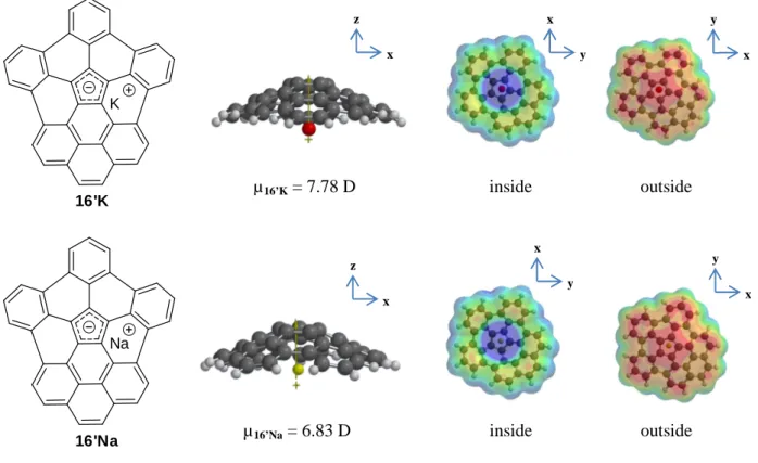
In Figure 12 and 13, properties of concave complexes 16’K and 16’Na and highly curved short [5,5] carbon nanotube cap 8 synthesized by Scott 26 are shown.
16'K K
16'Na Na
Figure 12: Calculated dipole moments and electrostatic potential surfaces of 16’K and 16’Na x z y x x y µ16’Na = 6.83 D µ16’K = 7.78 D x z y x x y inside outside inside outside
18 8
Even if 8 appears to be quite more suitable for hydrogen adsorption due to its apparent higher available adsorption surface, 16’K and 16’Na are believed to be even better candidates. Indeed, cations would not only increase or equal the dipole moment of 8 but could also act as spacers between curved PAHs, thus expanding the ILD. The distances measured between the potassium ion and the central pentagonal unit of curved molecule was slightly higher (2.94 Å) than the one between sodium (2.62 Å), making 16’K the preferred alternative as hydrogen storage material. In Table 1, curvature of
8, 16, 16’K and 16’Na were qualitatively measured by taking the dihedral angle between peripheral
carbons and the cyclopentadiene unit (Figure 14).
Curved polyarene Dihedral angle [°] Dipole moment [D]
8 64.0 6.45
16 133.0 2.25
16’K 137.1 7.78
16’Na 136.9 6.83
Dihedral angles show that from 8 to 16 there is a high decrease in curvature resulting in the lowering of the dipole moment. However, even if the curvature of 16’K and 16’Na is of the same order as the one of 16, the dipole moment is considerably higher due to ionic interactions.
Figure 13: Calculated dipole moment and electrostatic potential surface of 8
Table 1: Dihedral angles and dipolar moment for 8, 16, 16’K and 16’Na
x y y x x z
Figure 14: Dihedral angles for 8, 16, 16’K and 16’Na represented in green.
µ8 = 6.45 D
8 16 16’K 16’Na
19
2.2 First strategy starting from 2,6-difluorophenylacetic acid
The first synthetic pathway which was considered starts with the synthesis of 1,3-bis(2,6-difluorophenyl)propan-2-one 13b from the corresponding carboxylic acid. Compound 13b will be further reacted with pyrene quinone by a double Knoevenagel condensation followed by addition of phenyllithium and finally, its reduction with LiAlH4. The fluorinated triphenylcyclopentapyrene 15b
will be reacted with γ-Al2O3 offering the cyclized molecule by loss of HF 30,31,39 (newly formed C-C
bonds). The last step will be the deprotonation of the molecule using KH yielding a potassium complex. It’s believed that KH would be a better candidate than NaH (see 2.1). The overall strategy is shown on Scheme 10. The first step i) was more critical than firstly assumed and the following sections claimed to find appropriate conditions.
2.2.1 Dakin-West reaction
Scheme 10: Strategy for the synthesis of 16’K starting from acid 17b
20
The Dakin-West reaction was initially used for the preparation of peptides starting from acid and amine precursors, but when it was carried out at room temperature instead of 0 – 4°C by Bhandari in 1998 40, acid-amine coupling wasn’t observed but a symmetrical bisbenzyl ketone was formed instead. Until its discovery, this reaction has been used many times for the synthesis of symmetrical ketones starting from acid precursors. The general procedure used was the following 41 : compound 17b was added to a coupling agent DCC and DMAP in DCM. Surprisingly in our case, a complex mixture of side products and no traces of 13b was observed by GC-MS analysis of the reaction medium. Even with slightly modified conditions (Table 2) no increase in total efficiency was observed. Indeed, traces of 13b were observed by GC-MS during the reaction but after filtration to eliminate DCU and acidic extraction removing the DMAP catalyst, many side products with no traces of 13b anymore were observed. Low temperature didn’t show any difference in mixture composition.
Coupling agent Conditions Final yield
A 40 DCC R.t., 1 night 0%
B 42 EDC R.t., 1 night 0 %, traces during rxn
C EDC -78 °C, 1 night 0 %, traces during rxn
The reason of such a bad result may be explained by the high electronegativity of the four fluorines in ortho-position affecting the methylene reactive center in such a way that a possible charge can be stabilized via inductive effects, widening the necessary time for eventual rearrangements; a difficulty encountered with this reaction is that the full mechanism is still not well known and the only proposed mechanism postulated by Bhandari S. et al. seems to be not realistic since the active species 17’ is the result of a highly improbable deprotonation in α of an acid group (Scheme 12).
21
ESI-MS analysis and computational investigations were further undertaken in chapter 2.3.2 to propose a more probable mechanism.
2.2.2 Ketonic decarboxylation
The ketonic decarboxylation is a very old thermic reaction used for the formation of symmetrical ketones and even for the formation of cyclic ketones from dicarboxylic acids 43,44. However, to our knowledge, such reaction conditions had only been applied to compounds bearing carboxylic acid as their unique functional group. Even so, because fluorinated compounds are known to show high thermal and chemical stability 45, this strategy was tested. Sodium carbonate, used as mild base catalyst was mixed with 17b and heated at 295°C. Unfortunately a mixture of many side products with no trace of 13b was observed via GC-MS of the crude reaction medium. It seemed that 17b was more sensible to high temperature than thought in the beginning.
2.2.3 Claisen condensation
Claisen condensation reaction was thought to be the method of choice for the synthesis of 13b because of the milder reaction conditions as compared to those of ketonic decarboxylation and better knowledge of the mechanism as compared to Dakin-West reaction. The method developed by Romer
Scheme 12: Bhandari et al. proposed mechanism of the Dakin-West reaction
22
et al. 46 allowed the formation of 1,3-diphenylacetone in excellent yield. However this approach adds an extra synthetic step to form the corresponding ester required for the condensation.
Esterification of 2,6-difluorophenylacetic acid 47
Esterification was accomplished by mixing thionyl chloride with 17b in EtOH and by heating the reaction mixture to reflux during four hours. Evaporation of EtOH and extraction with DCM gave 19b in 83 % yield. The use of thionyl chloride allowed a quicker reaction by first forming the acyl chloride making the carbonyl carbon more nucleophilic thus favoring ethanol attack to give 19b. The structure of the ester product 19b was confirmed via mass spectrometry and NMR analysis where an additional triplet and quadruplet corresponding to the ethyl group were observed as well as the disappearance of the O-H vibration (3100 cm-1) in IR spectrum.
Ester condensation of ethyl 2-(2,6-difluorophenyl)acetate
Ethyl phenylacetate 19b was added to NaH in toluene at room temperature and the reaction mixture was heated during one hour. The mixture was then allowed to cool down and quenched with HCl. The mixture was then heated under acidic conditions in order to decarboxylate. Extraction with DCM afforded 28 % of 13b. 13C-NMR analysis revealed the characteristic downfield shift of the keto-group at 200.1 ppm while the methylenic protons signal shifted downfield from 3.76 ppm to 3.91 ppm. Simultaneously the absence of ethyl signals confirmed the formation of bisbenzyl ketone 13b. But the low unsatisfactory yield let us look for the structure of side products in the acidified aqueous basic layer. The main product among acetic acid used during decarboxylation step was identified to be acid
17b. This allowed us to think that the crucial step could be the acidic quenching of 20b since
retro-Claisen might occur. This side reaction was already observed by Romer et al. when quenching was achieved at relatively high temperature (>30 °C) but has been completely avoided at lower temperature 46. Indeed, under the initial alkaline conditions at the beginning of the quench, the β-keto
Scheme 14: Esterification of 17b
23
ester is hydrolyzed to the β-keto acid, which undergoes a retro-Claisen reaction rather than decarboxylation at high temperatures (60°C) (Scheme16).
However, even for a quenching at 0°C, retro-Claisen was observed in our case maybe due to the fluorine atoms making the carbonyl reaction center more electrophilic.
2.3 Second strategy starting from 2,6-dichlorophenylacetic acid
Species synthesized by Thilgen using the HF elimination strategy (see 1.4) did not imply highly curved geometries suggesting that such techniques are not appropriate for extremely curved molecules. 32 Synthesis of strained 16 would necessitate four ring closures in one step to introduce curvature. That’s why FVP method or palladium catalyzed Suzuki reaction were considered for the ring closure of chlorinated precursors. 28 Moreover, the new pathway was designed in such a way that a step involving phenyllithium addition on cyclopentadienone derivative followed by reduction was avoided. Indeed, this reaction had already been realized by Weber (see 1.4) starting from 14a but really small amounts of 15a with 22 and 22’ as major side products were obtained (Scheme 17).
Ph O Ph 1. PhLi 2. LiAlH4 15a + Ph Ph O H Ph Ph Ph H Ph 22' Ph Ph O H Ph + 22 14a
In the newly proposed pathway, cyclopentadienone derivative 14c would be condensed with tosyl hydrazine followed by elimination of the tosyl group under basic conditions offering the diazo compound 24 which can react with benzyne to give phenyl dibenzo-indenopyrene 25, or further reduced providing phenyl dibenzo-indenopyrene 26. Another advantage of such a new strategy is that one site will already be closed (in red). Finally, compound 26 will be subjected to flash vacuum pyrolysis or Suzuki reaction to close the three remaining rings (in green). The overall strategy is shown on Scheme 18. Unfortunately step i) was here again more critical than thought and the following sections would claim to find efficient synthetic strategies.
Scheme 16: Retro-Claisen reaction of 20’a giving 2 equivalents of 17a
24
2.3.1 Dakin-West reaction
The same procedure as followed under 2. 2. 1 was used. Reaction conditions tested are summarized in Table 3.
Scheme 18: Strategy for the synthesis of 16’K from the acid 17c
25
Coupling agent Base catalyst Conditions Solvent Final yield
A 40 DCC DMAP R.t., 1 night DCM 0 %
B DCC DMAP R.t., 1 night THF 0 %
C DCC MIM R.t., 1 night THF 0 %
D DCC Et3N R.t., 1 night THF 0 %
E 48 DCC DMAP 56°C, 3h THF 0 %, but traces during rxn
Traditional procedures 40 gave again no trace of 13c and because of the very small solubility of 17c in DCM, it was decided to try the reaction in THF. Here again no traces of 13c were observed. The substitution of DMAP by MIM or the less nucleophilic triethylamine didn’t give better results. Finally, conditions used by Ho et al. for the coupling of ortho-nitro derivatives were tested. 48
Traces of 13c were observed but in a too small amount and with so many side products that purification was not attempted. For the five reaction conditions, a main product of 286 amu was identified via GC-MS. It may correspond to amide 27c but no further investigations to characterize and isolate it were undertaken (Figure 15).
Due to those unsatisfactory results, it was then decided to apply reaction conditions A to phenylacetic acid 17a to see whether 1,3-dibenzylacetone 13a could be synthesized by this way, as previously reported in literature where yields of roughly 60 % were obtained (Scheme 20). 40, 49 This will allow us to see if the bad results for 17b and 17c were due to human factors or if it was the consequence of reactivity changes induced by the halogens in ortho-position.
The procedure used by Fragnière was used and compound 13a was obtained as a light yellowish solid (oil at room temperature) in 36 % yield. This low yield suggested that hidden parameters could have unsuspected importance. The structure of 13a was confirmed thanks to mass spectrometry, 13C-NMR spectroscopy showing a characteristic chemical shift of 205.68 ppm for the carbonyl carbon and 1 H-NMR analysis where methylenic protons shifted downfield from 3.66 ppm to 3.72 ppm.
Table 3: Conditions tested for Dakin-West reaction of 17c
Figure 15: Possible structure of the main side product of Dakin-West reaction
26
The many intermediates detected by UPLC-ESI-MS during the reaction suggested that several equilibria were involved, making the control of the reaction parameters very tricky. Indeed, the presence of ions (for example, depending on the glassware washing process) could for example stabilize some charged intermediates, thus completely changing their distribution. The variation of ambient temperature may also have a considerable impact on equilibria.
In the following section, the reaction was followed by ESI+-MS analysis in order to allow identification of the intermediates involved and to postulate a possible reaction mechanism.
2.3.2 Investigations on Dakin-West mechanism
Even if the Dakin-West reaction is now widely used for the synthesis of symmetrical ketones, the mechanism is still not well known and very different yields are reported in literature suggesting that many parameters may affect the reproducibility of the experiment. 33 Attempts to elucidate the mechanism by ESI+-MS analysis supported by computational calculations were undertaken following the method recently used by Dalla-Vechia et al. 50 for the mechanism elucidation of analogous Dakin-West peptide synthesis.
2.3.2.1 Postulated mechanism based on ESI+-MS analysis
A possible reaction pathway is postulated on Scheme 21. After the molecule numbers, letters a, b or c were added corresponding to X = H, F or Cl. UPLC ESI+-MS analysis of the crude reaction mixture were undertaken during the reaction of 17a with DCC and DMAP.
Starting acid 17a and DMAP were detected in the UV spectrum and a mass range of 150 – 600 amu in positive detection mode was used. Adduct 18a, anhydride 28a, DCC, DCU and acylamide cation 29a were all observed via ESI+-MS during the mixing of the starting reagents (Table 4).
27 X X 17 O2C X X 17' HO2C DMAP DCC X X O O N N Cy Cy 18' X X O O HN N Cy Cy 18 A B1 B2 O O O 28 X X X X O O X X N O X X N + DMAP + DMAP O O X X X X O 28' or 29 + DMAP O O O 30 O O O 31 O 13' O 13' O CO2 X X X X X X X X X X X X X X X X X X F G H I 29 C D E DMAP + 17' 28' DMAP + DMAPH + DMAPH + DMAPH + 29 + 29 28 DMAP Further cycles 28' + 13' O X X X X + DMAPH Rapid ion exchange O N H NH Cy Cy
28
After only fifteen minutes, the desired bisbenzyl ketone 17a was observed with a complex mixture of side products where DCU, DMAP, anhydride 30a, amide 27a, diketone 32, enol ester 32’ and N-acylium 33 were the solely identified structures (Figure 16). No mechanism was found to explain the formation of 27a, but 32 and 32’ should result of the reaction between 13’a and 29. Cation 33 would be probably produced after the nucleophilic attack of 30 by DMAP on the most hindered carbonyl group.
Molecule M ESI-MS: m/z Corresponding ion
17a 211.14 [M+H]+
27a 218.20 [M+H]+
30 373.26 [M+H]+
32 329.22, 351.13, 392.17 [M+H]+, [M+Na]+, [M+Na+ MeCN]+
33 359.23 [M]+
After 24 hours, the crude mixture composition had not evolved suggesting that key steps were at the really beginning of the reaction before thermodynamical equilibration occurred. The presence of DMAP at the end of the reaction proved its role of catalyst.
2.3.2.2 Computational calculations on the Dakin West reaction intermediates Computational calculations were performed at the B3LYP level using the PCM solvation model 51 available in the Gaussian09 package in order to corroborate the feasibility of the reaction. B3LYP/6-31G* geometry optimizations were done in DCM by following the same procedure as those used under 2.1. Single point energy calculations at HF/3-21G were done on the optimized structures using Spartan 10’ for visualization of the orbitals. The whole charged structures were computed with their corresponding counterion in order to handle a neutral system. The electrostatic energy potential surfaces of all the charged structures were computed to see where the counterion is preferably located.
Figure 16: Additional identified structures observed after 15 minutes
Table 5: Species detected by ESI+-MS after 15 minutes C23H20O2 C23H20O2
29
Each step of the postulated mechanism described in Scheme 21 was considered separately. If there were many possibilities for a step, the most probable pathway was chosen according to the calculated Gibbs reaction enthalpies and the qualitative concentration of reactants in the reaction media. Chlorinated compounds were also calculated to see which step could be critical.
Step A X X 17 O2C X X 17' HO2C DMAP + DMAPH a: X =H c: X =Cl -15.91 kJ/mol 5.74 kJ/mol
The Gibbs reaction enthalpy of 17a showed that even if the reaction is found to be slightly endothermic, the energy barrier is so low that it can easily be overcome at room temperature. For 17c, the reaction was found to be spontaneous. This difference is due to an important change of the dihedral angle 4 – 7 – 8 – 12 from 60.67 ° in 17’a to 3.3 ° in 17’c (Figure 17).
This geometry difference would be the result of a better electrostatic stabilization of carboxylate in the second case as illustrated by the calculated Mulliken charge distribution (Table 6).
Scheme 22: Deprotonation of 17
Figure 17: Geometry changes of acetate group between 17’a and chlorinated 17’c. Numbering of atoms for Mulliken
charges assignment achieved in Table 6
30
Atom Mulliken charges [a.u.]
X = H (17’a) X = Cl (17’c) 1 -0.09 -0.04 2, 6 0.03 -0.11 3, 5 -0.09 0.49 4 0.20 -0.02 7 -0.14 -0.18 8 1.45 1.55 9, 10 0.00, 0.07 -0.44 11 -1.10 -1.06 12 -1.13 -1.21
The main difference was noticed at carbons 3 and 5 where strongly positive Mulliken charges in 17’c were observed due to the presence of adjacent electronegative chlorine atoms. This would lead to electrostatic attraction with the acetate anion. Furthermore, maximal electrostatic repulsion between chlorines and negatively charged oxygen would also favor this geometry.
In Figure 18, planar interactions between the LUMO of DMAPH+ with HOMO of the carboxylate are illustrated.
Table 6: Mulliken charges of 17’a and 17’c computed from B3LYP/6-31G* calculations
31
Step B
This reaction step is quite endergonic giving rise to roughly 0.02 % of 18’, but because the next step is highly exergonic, 18 will be immediately consumed. Therefore with enough time, this activation barrier would probably be overcome. However, experimental observations showed that production of DCU (Step C) was instantaneous and this tells us that there must be a small discrepancy between calculations and real experiments. One might be closer to the experimental value by explicitly modeling the solvent molecules but this would considerably increase the time of calculations.
When geometry optimization of the ion pair 18’ – DMAPH+ was run, they immediately combined releasing 18 and DMAP. This would suggest that the reaction was concerted; a possible transition state is postulated in Figure 19.
No transition state calculations were investigated due to the arduous procedure for such researches.
Step C
Two possible reactions were investigated. Each of them was strongly exergonic. Gibbs reaction enthalpies are of the same order between 28a and 28c formation, except in the second possibility in
Scheme 23: Formation of 18 starting from 17’ and DCC
32
which 28c formation is less favored. As already found in step A, this will be due to the higher stability of 17’ in chlorinated compound.
Step D
If anhydride 28 and DMAP were calculated separately, Gibbs reaction enthalpies were too high (72.56 kJ/mol or 57.64 kJ/mol for chlorinated compound). But when calculated together, they looked to be roughly 13 kJ/mol more favorable for chlorinated species. This will be again attributed to the higher stability of 17’. Furthermore Mulliken charges at centers 1 and 2 were found to be 0.62 a.u. in
28a and 1.53 a.u. in 28c making the latter a better candidate for nucleophilic attack. Nevertheless, the
reason of such a difference was not really elucidated.
Scheme 24: Formation of anhydride 28 starting from 18 and 17’ in the first possibility and from 18 and 17 in the second
33
Step E
Here again, the computation of anhydride with DMAP gave better results than separated species. At first, formation of 28’c was thought to be favored over 28’a due to inductive effect of the chlorines which should stabilize the negative charge created after deprotonation by DMAP. Nevertheless this trend was not observed and the reaction was found to be even slightly less favorable for 28’c. Indeed, mesomeric effect should also be considered and resonance structures were drawn below.
For 28’a, there were two additional contributing structure compared to 28’c (Scheme 27, 28). Thus, negative charge was more evenly stabilized in 28’a.
This observation was confirmed by the calculated Mulliken charge distribution (Table 7).
Scheme 26: Deprotonation of 28 by DMAP
Scheme 27: Contributing structures for 28’a
34 8 2 1 6 5 4 3 7 O 10 O9 R X X 28' H
Atom Mulliken charges [a.u.]
X = H (28’a) X = Cl (28’c) 1 -0.31 -0.24 2, 6 0.19 0.03 3, 5 -0.28 0.28 4 0.72 0.51 7 -1.06 -1.08 8 2.00 2.06 9 -1.16 -1.14 10 -1.49 -1.47
Moreover another effect was noticed in the calculated structures. The dihedral angle between
H – 7 – 4 – 3 was found to be 0.10 ° in 28’a versus 26.45 ° in 28’c. In the latter, overlap of the anionic
p-orbital with π-orbitals of the benzene ring was hindered (Figure 20). This may be caused by high electrostatic repulsion between the chlorine atoms and oxygen atom 9, or simply by sterical hindrance of the substituents in ortho-position.
Steps D and E are in competition and were thought to be key steps. Indeed, if nucleophilic attack was preferred, the reaction would stop at this point. Production of 28’ is absolutely required to follow the desired reaction pathway. When X=H, it was found that Gibbs reaction enthalpy of E was slightly preferred, allowing further steps to proceed; When X=Cl, nucleophilic reaction is favored by roughly 11 kJ/mol, thus hindering the production of the active species 28’c. This might be the reason why the Dakin-West reaction wouldn’t work for ortho-dihalogenated compounds.
Table 7: Mulliken charge distributions of 28’a and 28’c
35
Step F
For the three following postulated possibilities, the counterion of the anionic species is DMAPH+, but omitted in the scheme for clarity reasons.
First possibility ∆∆∆∆rGtot= -33.71 kJ/mol ∆∆∆∆rGtot= -32.39 kJ/mol 28 X X O O O X X 28' + O2C X X 17' O O O O X X X X X X 30 a: X =H c: X =Cl
Deprotonated 28’ would react with anhydride 28 to give species 30 with deprotonated acid 17’ and DMAPH+. Surprisingly, there was no big enthalpy difference between a and c while 17’c has been found to be more stable in the past steps. Therefore, species 30 would be less stable for chlorinated compound. Electrostatic repulsion between chlorines and oxygen in 30c (in red) would force the molecule to adopt a geometry in which oxygen atoms are closer (in blue), thus destabilizing the molecule (Figure 21). Distance between oxygen decreased from 3.09 Å in 30a to 2.8 Å in 30c.
Scheme 29: Nucleophilic attack of 28 by 28’
Figure 21: Destabilisation of 30c due to electrostatic interactions 30a 30c
36
Second possibility
Nucleophilic attack of 28’ on N-acylium 29 formed in step D released acetate 17’ and compound 30.
Third possibility
Adduct 18, formed in step B will undergo nucleophilic attack by 28’ producing 30, DMAP and DCU. In all possibilities, reactions were found to be exergonic, but in the second case, species 29 was thought to be present in relatively small quantities while adduct 18 and anhydride 28 should be present in higher concentration. Of these two possibilities, the last one presents an advantage, namely the production of DCU which will precipitate and thus strongly favor the reaction.
Scheme 30: Nucleophilic attack of 29 by 28’
37
Step G
The next step was delicate because the base can either abstract a proton releasing a stabilized β-ketoester 30’ or act as a nucleophile (Scheme 32).
DMAP + 2 O O 3 O O X X X X X X O O O O X X X X X X H1 + DMAPH O O O X X X X O X X N N + 30 30' 29 31 A C B N O O X X X X 33 O O X X N + 17' DMAP + DMAP + a: X =H c: X =Cl
Normally, the first case would happen but in the computed electrostatic energy surface, it can be seen that at center 1 there would be highly sterically hindred due to oxygen atoms and the phenyl substituant (Figure 22); thus DMAP would probably better act as a nucleophile. Even if B could also happen (traces of 33 were observed in ESI+-MS analysis), the reactive center of choice should be 3.
C was the only possibility which was considered (Scheme 33).
Scheme 32: Deprotonation of 30 by DMAP (1) and nucleophilic attack on (2) or (3)
Figure 22: Electrostatic potential surface of 30c 1
38
Unfortunately, the Gibbs reaction enthalpy which was only computed for 31a was too high. It should be kept in mind that 30 and the ion pair 31-29 would have many degrees of freedom increasing the probability that the calculated energy minimum wouldn’t correspond to the global minimum but to a local minimum. No further calculations for finding a better energy minimum were undertaken.
Step H
This decarboxylation step would occur quite easily although not exergonic for chlorinated species. Anyway, gas evolution will push the equilibrium towards product 13’. Compound 31 was not observed experimentally because the ESI-MS detection mode was positive.
At this point, as assumed by Dalla-Vechia L. et al. in their calculations, a fast counterion exchange has been considered (Scheme 35).
Scheme 33: Nucleophilic attack of 30 by DMAP
Scheme 34: Decarboxylation of 31
39
However, it should be kept in mind that some species as 29 would not undergo such a counterion
exchange but suffer a nucleophilic attack of 13’. This explains the detection of traces of 32 (see 2.3.2.1) (Scheme 36).
Step I
Reprotonation of enolate 13’ is largely exergonic in the two cases regenerating the DMAP catalyst.
General considerations
Identification of anhydride 28 as an intermediate gave us the idea to explore another synthetic approach which would first start from the synthesis of anhydride further treated with DMAP to release
13. In this way, the production of DCU and nitrogen containing intermediates could be avoided and
possible amide side product formation as 27a and 27b could be avoided (see 2.3.1 and 2.3.2.1). Bhandari et al. have already tried such an approach starting from acyl chloride for the synthesis of
Scheme 36: Side reactions which could occur before counterion exchange
40
anhydride but without obtaining any trace of 13a. Despite these poor results, it was decided to test this new pathway.
2.3.3 Anhydride pathway
Based on the work of Tran et al. in which they achieved a variant of the Dakin-West ketone synthesis by the reaction of phenylacetic acid 17a with acetic anhydride catalyzed by MIM releasing 1-phenylpropan-2-one 52, it was thought that by starting with 2-phenylacetic anhydride 28a, the desired bisbenzyl ketone 13a should be obtained.
Anhydride synthesis
Anhydrides 28 were prepared according to Selinger Z. et al. who synthesized fatty acid anhydrides by the reaction of the corresponding acid with DCC in excellent yields. 53 A solution of 17 was added to DCC in dry DCM and allowed to react. The suspension was filtered and the solvent evaporated. Because DCU is slightly soluble in DCM 54 but really less soluble in MeCN, the obtained white solid was dissolved in the latter at 0°C and filtered removing the remaining DCU. Compounds 28a-c were obtained as white solids in 89 – 98 % yield. The presence of 28a-c were confirmed by 1H-NMR where methylenic protons are shifted downfield from 3.66 ppm in 17a (4.08 ppm in 17c) to 3.74 ppm (4.16 ppm) and integral values rose from 2H to 4H.
In the 13C-NMR spectrum, a carbonyl carbon signal shifted upfield from around 178 ppm to characteristic 168 ppm in 28a (164 ppm for 28c). The disappearance of the O-H vibration of the acid group 17 at around 3000 cm-1 and the classical two bands for the carbonyl groups of 28 at around 1800 and 1700 cm-1 were observed via IR spectroscopy. Masses of 277.09 amu corresponding to [28a + Na]+ and 413.03 amu for [28c + Na]+ were observed by UPLC ESI+-MS. An acid moiety was also detected but can be attributed to the acidity of the column. Under those conditions, anhydride 28 would partially hydrolyze releasing two acid molecules 17.
41
Bisbenzyl ketone synthesis
DMAP was added to 28 in dry DCM and the reaction mixture was stirred during six hours. Thanks to ESI+-MS of the crude reaction mixture, the formation of 13a was detected whereas no traces of 13c were identified. The solution was then quenched by adding HCl and the organic layer was washed with NaHCO3. Compound 13a was obtained in 81 % yield as yellowish oil crystallizing in the fridge.
Identification by mass spectrometry and NMR experiments gave exactly the same results as those obtained under 2.3.1. The obtained total yield for this anhydride pathway was 72 %, which was really satisfaying. Moreover, this would contradict Bhandari S. et al., which had stated that it was impossible to synthesize 13a following the anhydride pathway. 40
Unfortunately, no traces of 13c were obtained and as predicted in section 2.3.2.2 by the fact that DMAP would rather act as a nucleophile than as a base, thus only producing N-acylium 29c (Scheme 40). ESI+-MS of the crude reaction mixture gave a mass of 309.06 amu confirming the presence of
29c.
Use of a non-nucleophilic base could favor 28’c formation. Therefore Hünig’s base (DIPEA) was tested instead of DMAP. Its poor nucleophilicity is due to the steric shielding of the nitrogen atom by the ethyl and the two diisopropyl groups, making the lone pair only accessible for a proton. However, no reaction was observed under these conditions. This could be due to the steric hindrance caused by the chlorine atoms which would hinder the approach of DIPEA.
Scheme 39: Decarboxylation of 28 giving ketone 13


![Figure 8: Possible mechanism of the cove-region closure process for benzo[c]phenanthrene condensation showing coordination on the aluminium oxide surface, aromatic transition state, and Al-F bond formation](https://thumb-eu.123doks.com/thumbv2/123doknet/15025048.684918/19.892.125.779.118.316/possible-mechanism-phenanthrene-condensation-coordination-aluminium-transition-formation.webp)