THE CONCEPT OF "BACKGROUND COMPONENT" IN IASA SOFTWARE
MODEL.
ABDELFETAH SAADI*, DJAMEL BENNOUAR **, ABDERRAZEK HENNI * *
National Superior School of Computing, Oued Smar, 16000, Algiers, Algéria. **Faculty of Science, Dpt Info, Saad Dahleb University, 09000 Blida, Algéria.
ABSTRACT
This article describes a new approach for software component architecture to deal with dynamic adaptation of software systems. We introduced the concept of "Background Component" in our IASA software component model. The Background components are a set of components that run at the back ground level to adapt dynamically the software architecture. The proposed approach is close to that of intelligent agents which manage all types of events during the deployment or the implementation of the architecture.
KEYWORDS:
Software architecture, Background Component, component model, dynamic adaptation.
1 INTRODUCTION
The concept of component software plays a significant part of the IT landscape, particularly in the areas of software engineering, distributed systems and networks. Like any emerging concept, the ambiguity prevails when it comes to give a clear definition. But we can rest on a relatively consensual definition [1]:
Software components are units for composition of software. Or: A component is a software entity, developed and sold by a company and used by one (or more) client (s) for composing software.
The field of software architectures [1] aims to describe the structure of software as an assembly by interconnecting components. From the industrial point of view, the needs in terms of software components expressed by the need for technology to compose applications from reusable software components [1]. The increase in the needs of developing industrial systems has caused the increasing complexity of systems (distributed functions, interaction with the outside world ..., etc), moreover the requirements of reliability is always higher [1]. Today there are many solutions based on industrial components such as Microsoft COM / DCOM, JavaBeans, EJB components and CCM (CORBA Component Model)… etc [1]. Currently, many companies are interested by the field of software architecture and the design by assembling components. This interest is motivated mainly by reducing costs and development time of applications [2].
We can distinguish two types of architectures [1]: the static architecture and the dynamic architectures. In a static
architecture, components and their topologies are completely defined in the specification [1]. The composition and structure of static architecture cannot change during execution. The static architectures cannot meet a considerable number of needs, including needs for adaptability, failures resistance, hot upgrade, optimization of resources, and structural or behavioral changes. The management of these needs can be accomplished in the context of dynamic architecture. By cons, the Specification of dynamic architecture allows planning the changes of topology that will take place at runtime. A dynamic architecture can:
Managing a system failure and switch to a safer topology (stable topology).
Managing a changing environment (System client - server).
The evolution of architecture and the dynamic adaptation should not be always known before the execution of the corresponding application [2]. The evolution mechanisms of a system can decompose architecture, replace, create, delete, enable or disable components or connectors. These mechanisms must be executed without stopping the execution of the corresponding application [2] [5]. Currently, we can found several problems in the specification of the dynamics in architecture description languages. We can cite some of these problems in this following:
The specification of behavior is done by formal languages that are difficult for practitioners (e.g. Wright); formal languages are used to demonstrate some distinctive architectural features such as the absence of deadlocks.
In a dynamic software architecture, we have two parts that needs the update, the structural part (add, delete, inhibition of component or connector) and the behavior part (that is to say, the possibility for a single component to behave differently according to environment in which it operates or in time).
The policy necessary to adapt a system where the environment is dynamic is not guaranteed by most of the modeling component.
These dynamic aspects are not treated by several ADL [6]. In other ADL, dynamic aspects are either limited or specific to some situations.
Our component model IASA was defined to allow a flexible specification of software architecture. It allows the specification of varied topologies, some of which cannot be specified by the current ADL. This model has been proposed and developed by Mr. Bennouar and al at LRDSI1 [7]. This model can reduce integration issues by describing the interfaces between hardware and software. To avoid misunderstandings, this model has a strong and precise semantics.
In this work we have introduced the concept of Background Component, which is achieved by adding of components that run in the background. When the instance starts, these components work like intelligent agents by allowing the proper management of all types of events. These events can be provided either during deployment or during the implementation of the architecture.
This article is organized as follows. Section II defines basic elements of the IASA component model, we begin with the notion of components and connectors, and then we present the access points and ports. In Section III we introduce the concept of background component. Section IV presents the related work. Finally, in Section V, we close with conclusion, prospects and our future work.
2 THE IASA BASIC MODEL ELEMENTS
IASA2 is based on the following concepts: access point, port, component, envelope and connector [6]. These elements represent the fundamental concepts of the IASA ADL called SEAL3 [7]. The action concept, largely inspired from the OMG Precise Action Semantic [5] is used to describe miscellaneous architecture behaviors.
2.1 THE IASA COMPONENT
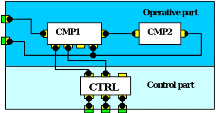
The IASA component model defines a specific organization for the internal view [7] which consists of two parts: the operative part and the control part
1
Research and Development Laboratory of Computer Systems.
2
Integrated Approach Software Architecture.
3
Simple and Extensible Action Language.
(Figure.1). The operative part handles the core business. The control part is composed of a controller and number of components (tracing, exception, transaction…) providing the technical advices [7]. A component is instantiated in the whole application as a singleton.
CTRL
CMP1 CMP2
Operative part
Control part
Figure 1: The IASA component Model.
2.2 THE ENVELOPE CONCEPT
The main goal of the envelope is to provide a total isolation of the internal view of a component from the external world [6]. The envelope (Figure.2) is mandatory in the process of instantiating a component type. The envelope specifies for a component instance its deployment case which describes the deployment environment (machine, operating system, process, application server) and the exact nature of the component in such environment (process, main thread, threads, Servlet, EJB etc.) [7]. An envelope hosts all the resources needed to support communication aspect (i.e. adapters), to enable the specification of connections involving the port's structural elements and to handle aspects weaving operations of code [7].
Envelope
External Ports
Internal Ports
Figure 2: The Envelope Concept.
2.3 THE IASA ACCESS POINT
specification of an application [7]. It is used to define the ports of components. An access point exposes required or provided resources which may be data or operations. Communication mode and the resource time validity are among the properties of an access point [7]. An access point may be wired in an independent manner to another access point which is hosted in the same or a different port (Figure.1).This is not the case in current software architecture models and tools, where an interaction point, usually represented by an interface is considered as an atomic element despite its complexity [7]. The access points are organized into two categories: The Data Oriented Access Point (DOAP) and the Action Oriented Access Point (ACTOAP). An ACTOAP plays one of two basic roles: a server role or a client role. It supports a set of actions indicating the provided or required operation. A DOAP is usually provided with two specific actions: the send and receive actions [7].
2.4 THE IASA PORTS
A port [5] [7] is a regrouping technique of related access points. It maintains an abstract and a concrete views. The abstract view is represented by the concept of access point, the actions associated with the access point and a behavior. The port's behavior is represented by a set of valid rules defined in the SEAL language (Simple and Extensible Action Language) as described in [5] and [7]. Each rule shows how the required or provided resource must be used. IASA defines a number of specific ports. Among them (Figure.3) we find the ClientPort, the ServerPort and the AdvicePort. An AdvicePort is a ServerPort provided with actions explicitly associated with supported aspect activation mode. For now, the supported advice activation modes are: aroundFirstAction, AroundLastAction, proceedAction, beforeAction and afterAction [7].
DataPort (Out)
DataPort (In)
PeerPort
ServerPort
ClientPort
Figure 3: Graphics ports.
2.5 THE IASA CONNECTORS
The IASA connector [5, 7] model is largely inspired from computer network architecture. The model provides a behavioral view and a structural view. The behavioral view describes an interaction and the structural view defines the infrastructure needed to transport the interaction. The connector infrastructure is based on two kind of fundamental connector elements: [7]
Transport Connectors which are point to point connectors, composed by Basic Transport Connector, which can connect only two compatible access points (Fig.1). Service connectors which are primitive component oriented to support specific interconnection functionality (distribution, multiplexing, load charge balancing, etc.) as described in [5] and [7].
The designer is not concerned by the definition of new Service Connectors or Transport connectors which are predefined in the IASA approach and have a complete realization in the supported implementation technologies. The definition of the interconnection infrastructure is achieved in IASA by cascading Service Connectors using Transport Connectors.
3 THE CONCEPT OF BACKGROUND COMPONENT
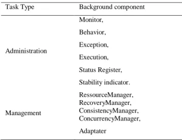
For the proper management and implementation of the architecture, we define a set of components that will be implemented as a background process or an intelligent agent, These components are called "Background Component", each of these components have a precise role in the functioning of the instance, Most of these components are running at startup of the instance and stopped at shutdown of the instance, some components can be started and stopped during the functioning of the instance, we define for the moment a dozen of these components, but some can be run in multiple copies, these components are classified into two categories (Table 1): "Background component" for administrative tasks. "Background component" for management tasks. The studies that we have done around this area and the work of Marc Leger [11] allowed us to define all the components shown in Table 1.
Table 1: The background component.
Task Type Background component
Administration Monitor, Behavior, Exception, Execution, Status Register, Stability indicator. Management RessourceManager, RecoveryManager, ConsistencyManager, ConcurrencyManager, Adaptater
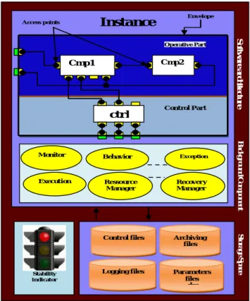
The figure below (figure 2) illustrates an example of an architecture instance running.
Instance Control files Logging files Archiving files Parameters files des Monitor Behavior Execution Ressource Manager Exception Recovery Manager Stability indicator ctrl Cmp2 Cmp1 Operative Part Control Part Access points Envelope S o ft w a re a r ch it ec tu r e B a c k g r o u n d C o m p o n e n t S to ra g e S p a ce
Figure 4: An instance of architecture.
We present in what follows the role and functions of each component:
3.1 RESSOURCEMANAGER
This component is responsible for the management of resources, it manages all components of the application and registration operations of reconfiguration [11]. Each component of the control section must be registered with the resource manager. The registration of a component is done through a specific controller; this record is done automatically if the component is instantiated by a language of action or transaction reconfiguration (CreateComponenet example). The application state is defined as all states of all components that make up [11]. Each component is responsible for the activation of the shares for its own operations reconfiguration primitives
3.2 RECOVERYMANAGER
This component aims to implement the recovery strategy of the system in case of breakdowns, regarding the recovery strategy, several types of exceptions are detected, the system can adjust the recovery based on the type of emergency encountered [11]. The recovery policy is flexible. This component uses the recovery of takeover by cancellation (Rollback) of the operation that failed. In the case of the immediate update, the transactions recorded in
the log of actions reconfiguration are performed in reverse order of their first run. This recovery by undoing operations is much less intrusive in a system implementation that reinstantiate components involved in reconfiguring their former state following the principle of control points (checkpointing). Upon cancellation of a reconfiguration action after an exception. The recovery is automatic and canceling reconfiguration action is executed and the client must be notified, or recovery is manual and in the latter case, the rollback must be explicitly invoked by the client.
3.3 CONSISTENCYMANAGER
The main objective of using this component for dynamic reconfiguration is to maintain consistency of the system state [11]. This consistency is defined by a set of integrity constraints in the form of invariant configuration and preconditions and post conditions of operations reconfiguration. The consistency check in the system is the responsibility of this component.
3.4 CONCURRENCYMANAGER
This component implements the policy management system of Concurrency. There are generally two main types of strategies for managing Concurrency in a dynamic system [11]: optimistic strategies (or by validation), and pessimistic strategies (or by locking). The basic granularity of locking is the action of reconfiguration for each component; component status is not always available and therefore locking directly. Each reconfiguration operation is potentially in conflict with other operations for updating or reading the state of the application. [11] A graph of waiting on the locks is maintained between the actions in order to detect possible cycles, upon detection of deadlock between actions reconfiguration, component cancels a transaction at issue, the recovery manager (RecoveryManager) will attempt to repeat the actions after a specified time (configurable). The number of tests for action is also customizable.
3.5 ADAPTIVE
This component describes the changes to be implemented on architecture in order to incorporate new components; it is composed of many adaptation operations [11]. These describe the various changes to implement by the components of the architecture. The description of this adaptation is divided into three distinct parts:
The update of the structural part of the architecture, The update of the behavioral part of the architecture, The update of links between components.
We can take an example for integrating a new component in architecture, so this adapter has two adjustment operations. One describes the integration of new
component, the other models the changes necessary to integrate this new component. To integrate this component, it must add a port compatible for all components that will be connected with the port of this new component, it is also necessary to change the behavior of the new component in order to add the interactions between it and the changed components.
3.6 MONITOR
The monitor is the heart component of the system architecture. He plays the role of coordinator of the execution of actions to reconfigure the system. The monitor implements the model of dynamic reconfiguration. This component manages the creation, the limiting, the spread, and the validation of actions reconfiguration of the architecture [11].
3.7 BEHAVIOR
The managing operations of the components of the presentation part and its structure are the dynamic behavior of the latter. The implementation of this behavior is provided by the behavioral component. The implementation of this component is completely done in the language of action SEAL [3] [5]. This component can have one or more behaviors. Such behaviors can be defined within the component or imported from outside, for that it has multiple ports by default to select an internal behavior or load an external behavior. Through this approach it becomes easy to specify for single architecture various behaviors, each setting its own way of changing the presentation part.
3.8 EXCEPTION
Exceptionally during the execution of an action to reconfigure the architecture or a user action, or the This component's role is to redirect an exception occurred on a port of any component to a single port. This port is the exception port of the component that should be connected to the external connector by a delegation. This component represent the mechanism for handling errors occurred during the life cycle of composite component, these errors generally occur environment action.
3.9 RUNTIME
This component allows to execute the actions of evolution and reconfiguration of the architecture, It makes the verification and validation and analysis of a composite component and monitoring the compliance and consistency of model, After each reconfiguration, it performs an audit of stability and during this operation there's instantaneous creation of various views of
architecture which could reveal the sources of potential instability.
3.10 STATUS REGISTER
Is a component that represents a state register that records the state of all components, connectors, ports and access points, this register will learn about the state of any elements of the architecture at any point of execution, it serves as basic element to see the overall status of architecture.
3.11 STABILITY INDICATOR
It indicates whether the architecture is stable or unstable, it has three states:
Red: indicates that the architecture contains errors and it is
unstable.
Orange: indicates that the architecture is stable, but it
contains warnings.
Green: indicates that the architecture is stable and free of
errors.
4 AN ILLUSTRATIVE EXAMPLE
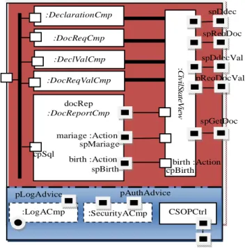
In this example, we realized a software system which enables the citizen to access through the internet to various services of a local government institution called the APC (The town council) [7]. The most required services from the APC are the production of official documents exposing important events such as the birth certificate and the marriage certificate. Inside the APC, the service delivering such official documents is called the Civil State Service. The design of the CivilStateServiceCmp component is shown in Figure 5.
This application is composed of a number of components, each one oriented to handle a specific functionality of the civil state department of the APC (figure 10). The components DeclarationCmp and DocReqCmp are oriented to enable the participation of the citizen in the process of populating the E_APC databases with accurate data concerning them. DeclarationCmp handles the declaration of new events such as birth, death, marriage or divorce. DocReqCmp is used to request miscellaneous certificates and, in the same time, is used to enter citizen data if these later were not yet captured in a previous declaration or document request.
When the CivilStateServiceCmp instance starts, a set of background components will be launched and are running in the background level to adapt dynamically the software architecture, some of these components are:
Monitor: coordinate the execution of actions to reconfigure the system.
any component to an exception port of Exeption component.
Execution: allows executing the actions of evolution and reconfiguration of the architecture.
Status Register: it serves as basic element to see the overall status of architecture.
Stability indicator: It indicates whether the architecture is stable or unstable.
RessourceManager: manage the resources; it manages all components of the application and registration operations of reconfiguration.
RecoveryManager: implement the recovery strategy of the system in case of breakdowns.
ConsistencyManager: maintain consistency of the system state.
Scenario of working: These components are not a part of CivilStateServiceCmp architecture; they are initiated automatically or manually selected by the architect.
spReqDoc spDdec :DocReqCmp :DeclarationCmp :DocReqValCmp :DeclValCmp spReqDocVal spDdecVal CSOPCtrl :SecurityACmp :LogACmp pAuthAdvice docRep :DocReportCmp spGetDoc pLogAdvice :C iv ilS ta te V ie w birth :Action mariage :Action cpBirth spBirth cpSql spMariage birth :Action
Figure 5: Civil State Service application.
System Start Background Component Start System Starting Stop System Stoping Background Component Starting Stop
Background Co mpo nent Stoping
Figure 6: Scenario of working.
When the system is started, all components will also start, when the system is stopped, all components will also stop (figure 6). This concept is closer to the phenomena of intelligent agents that manage all types of events during the deployment, the implementation or execution of the architecture. It allows to the software models to accommodate all types of systems. This make software model more secure, flexible and adaptive.
5 RELATED WORK
Currently there are several component models that use approaches to self adaptation and self reconfiguration, each model has advantages and disadvantages, Among of these models we can mentioned: MaDcAr[12], K-Component [14], Safran [15], FORMAware [16] [17], OpenRec [18].
5.1 MaDcAr
[12] is an engine model of the assembly, allowing the adaptation structural logic and adaptation of the implementation of systems based component. An engine assembly can, using a set of components and a description of the system, assemble a subset of components satisfying the description of this system. An engine is composed of: A context manager,
A description of application, A political assembly.
Discussion
The model is interesting but the approach has serious shortcomings [13]:
Structural change, such as adding a role, requiring the complete redeployment of system with a new design incorporating the new role. MaDcAr requires a shutdown of the application for this and do not allow the resumption of the execution point.
Behavioral adaptation, which involves the replacement of a component requiring a role, is carried out following a structural change in the component architecture “Concrete”.
5.2 K-Component
[14] is an architectural model for building distributed systems, self flexible and adaptable software based component. It allows coordinating the adjustments of components in a decentralized manner and achieving self-optimization and self-repairing system. A component supported by K-Component includes a service interface provided and, optionally, services interfaces required. It has different states and outlines actions for adaptation. It
has connectors that connect the interfaces required to provide interfaces [13].
Discussion
The model is interesting but [13]:
The policy of self repair is limited to the reconnection of components whose dependencies have been broken because of problems in the communication infrastructure [13].
The approach does not specify how such a process ends [13].
Management of consistency is low in the adaptation process [13].
5.3 Safran
[15] is a generic approach to build adaptive systems based on components. It supports the structural adaptation and behavioral adaptation through parameterization and redirection service invocations. It is based on the Fractal component model which uses the mechanisms of reflection [13].
Discussion
Safran is a model that is rich in languages dedicated to every aspect of self-adaptation. However, Safran suffers from problems inherent in Fractal [13]. There is no parallel execution of adjustment as a result of partageabilite components [13].
5.4 FORMAware
[16] [17] is a software framework to develop and adapt dynamically distributed systems based on components. The dynamic adaptation is achieved through reconfiguration operations and is constrained by sets of rules for maintaining the architectural integrity known by architectural styles [11]
Discussion
FORMAware proposes a hierarchical component model, reflective, and open, it ensuring consistency of architecture reconfigured. [11] The dynamic adaptation of applications is achieved by reconfiguration operations as scripts in Java. The reflexivity and openness of the model allow the execution of dynamic reconfiguration unanticipated.
5.5 OpenRec
[18] is an open software framework for dynamic reconfiguration of component systems. He is particularly interested in the problem of synchronization between reconfigurations and execution of functional systems and
management of the state components reconfigured [11]. While many platforms only support one set of synchronization algorithm, OpenRec can choose from an extensible set an algorithm adapted for the architectural style of a given system [11]. The framework allows
observing the impact of algorithms
synchronization in terms of execution time and disruption of the functioning of systems [11].
Discussion
The objective of OpenRec is focused on the problem of synchronization between reconfiguration and execution systems reconfigured implies in particular a fine management of the condition of impacted components [11]. However, no mechanism to cancel the execution of an algorithm in case of error. The concurrency between reconfiguration is managed simply by their serial execution [11].
6 CONCLUSION
In this paper, we have introduced the concept of background component; we have also presented the IASA component model. The IASA specification is very simple. It can take care of the most direct manner possible the mental model of the architecture in both its aspects, structural and behavioral. It also allows the inclusion of dynamic aspects of architecture. The basic concepts of IASA model and background component that sets have been an implementation and integration as plug-in java in the environment and the workshop using the design IASASTUDIO [4]. The background component concept was evaluated in the context of a concrete project dealing with the design and implementation of a complex software system. This project was concerned by the design and implementation of a system oriented to manage the commerce of an X25 network products.
REFERENCES
[1] ACCORD project (assembly of components by contracts in
open distributed environment) "State of the art on the description language architecture" (June 2002). Technical review, Reference: Available 1.1-2, French, Date: June 2002.
[2] PRISM Laboratory Website
http://www.prism.uvsq.fr/index.php?id=167, University of Versailles.
[3] Hadjkacem M., “Modelling dynamic distributed applications architecture: Design and Validation“, Ph.D. thesis, University of Toulouse and Sfax, November 2008.
[4] Saadi A., "An action language for the specification and
Thesis, LRDSI Lab, The Saad Dahlab University, Blida, Algeria, June 2008.
[5] Bennouar D., Khammaci T., and Henni A., “Modeling the
Component’s Interaction Point in The IASA approach“, The Mediterranean Journal of Computers and Networks, vol. 4, no. 4, 2008, pp 188-197.
[6] Bennouar D., Henni A., Saadi A., “The Design of a
Complex Software System Using Software Architecture Approach“, ACIT 2008, 16-18 Dec, Hammamet, Tunisia 2008.
[7] Bennouar D, "An integrated approach to software
architecture", PhD Thesis, ESI, Algiers, 2009.
[8] Loulou I., Hadjkacem M, Jmaiel M., and Drira K. “Towards
a unified graph-based framework for dynamic component- based architectures description in z”. In ICPS’04: Proceedings of the IEEE/ACS International Conferenceon Pervasive Services, pages 227–234. IEEE Computer Society, 2004.
[9] ACCORD project. "Joining components by contracts, state
of the art and standardization. Technical Review, 2002.
[10] CHAUDET C., "P-Space: language and tools for describing
architectures for scalable dynamic components. Formalizing software architectures and industry”. PhD thesis, University of Savoie, French. December 2002.
[11] Leger M., "Reliable dynamic reconfigurations in component", phd thesis, MINES, ParisTech, May 2009.
[12] Grondin G., " MaDcAr-Agent: a model of agents
self-adaptive based component ". PhD thesis, Ecole Nationale Supérieure des Mines de Saint-Etienne, Saint-Etienne, France, 24 novembre 2008.
[13] Ballagnymocas G. "a component model based statements
for self-adaptation.", PhD thesis, university of pau and « pays de l'adour », 2010, French.
[14] Dowling J. “The Decentralised Coordination of
Self-Adaptive Components for Autonomic Distributed Systems”. PhD thesis, Dept of Computer Science, Trinity College,
Dublin, Ireland, 2004.
[15] Pierre-Charles D. " Développement de composants Fractal
adaptatifs : un langage dédié à l'aspect d'adaptation ". PhD thesis, Nantes, Nantes, Franch, 2005.
[16] Rui S. M, Gordon S. B, and Carrapatoso E. Formaware:
“Framework of reflective components for managing architecture adaptation”. In Alberto Coen-Porisini and André van der Hoek, editors, SEM, volume 2596 of Lecture Notes in Computer Science, pages 115 129. Springer, 2002.
[17] Rui S., Gordon S., and Carrapatoso E. “Constraining
architectural reflection for safely managing adaptation”. In Middleware Workshops, pages 139 143. PUC-Rio, 2003.
[18] Hillman J., Warren I., “An open framework for dynamic
reconfiguration”. In Proceedings of the 26th International Conference on Software Engineering (ICSE2004), pages 594-603, May 2004.
[19] Bennouar D., Khammaci T. and A.Henni, "A Layered
Connector Model for A Complex Software System Design", ACIT'04, the International Arab Conference on Information Technology, Constantine, Algeria, 2004.
[20] Bennouar D., Khammaci T., Henni A., "IASA, an
integrated approach to software architecture, Internal Report No. 03/07, Laboratory LRDSI, Department of Informatics, University Saad Dahlab, Blida, in January 2007.
[21] Saadi, A., Bennouar D., “The design and implementation of
a commerce manager system for the products of the X25 DZPAC network using IASA AOSA approach”, TR/SA00109, the LRDSI lab, Computer Science Department, the Saad Dahlab University, Blida 2009, Algeria (in French).
[22] Bennouar, D., Khider, H., Aspect Oriented Software
Architecture in the IASA approach, TR/SA00109, the LRDSI lab, Computer Science Department, the Saad Dahlab University, Blida 2008, Algeria.