Ren-Kae Shiue
S.M. National Taiwan University, 1988 S.B. National Taiwan University, 1986
Submitted to the Department of Materials Science and Engineering in Partial Fulfillment of the Requirements
for the Degree of Doctor of Philosophy in Materials Engineering
at the
Massachusetts Institute of Technology June 1996
@ 1996 Massachusetts Institute of Technology All rights reserved
Signature of A uthor ... . . ... Department of Materials Science and Engineering
May 10, 1996
C ertified by ... I... ... .. ... 76as W. Eagar Department of Materials Science and Engineering Thejsj Supervisor
A ccepted by ... . ...
Michael F. Rubner TDK Professor of Materials Science and Engineering Chair, De artmental Committee on Graduate Students MASSACHUSETTS INSTITUTE
OF TECHNOLOGY
MAY
2 1 1998
Active Braze Alloys for Metal
Single Layer Grinding Technology
by Ren-Kae Shiue
Submitted to the Department of Materials Science and Engineering on May 3, 1996 in partial fulfillment of the requirements for the Degree of Doctor of Philosophy in Materials Engineering Abstract
Components made of high-performance ceramics or superalloys are subject to strict requirements with regard to their geometric and dimensional accuracy. The surface finish and edge zone characteristics have a large effect on the component's performance. These requirements can not be met directly by the sintering process used in the manufacture of ceramic materials or traditional casting of superalloys. Grinding is both technically and economically the number one choice when one has to consider machining these materials. Metal Single Layer (MSL) grinding technology provides an altemative way to make use of the superabrasives, diamond and CBN, in grinding these materials. One of the primary challenges in MSL grinding technology is to develop suitable active braze alloy(s) which can bond the superabrasive grits. Ticusil (Ag-Cu eutectic+4.5 wt% Ti) and 70Cu-21Sn-9Ti (wt%) are two of the currently used active braze alloys. The primary failure mode of these two MSL wheels in the grinding test is transverse fracture and debonding of the diamond grits. The high applied load is responsible for transverse fracture of the diamond grit, and the intermetallic phase existing at the interface between the diamond and the braze alloy is one of the causes of the debonding of the diamond grits. Also, a finite element analysis shows that most of the residual thermal stresses and the thermal mismatch strains are localized at the diamond/braze alloy interface. This results in potential weakness of this area. Moreover, the inherent defects, such as voids, and the brittle intermetallics in the interface can cause crack initiation and propagation. Both deteriorate the life of the grinding wheel.
The failure of the braze alloy can be divided into two categories. If the grinding process is very abrasive, such as green concrete grinding, the wear resistance of the braze dominates the fracture of the braze alloy. On the other hand, failure of the braze alloy can also result from cracks at the interface. In such a case, the fatigue resistance of the braze alloy plays an important role in determining the wheel's life. The wear resistance of the braze alloy can be improved by introducing suitable hard particles. It was found that a braze alloy of 77Cu-23Sn-12.5Ti-7.5Zr-lOTiC-0.2C (by weight) exhibits excellent performance in a wear test (a ten fold improvement), which is further confirmed in the grinding test (a two fold increase in life). The fatigue resistance of the active braze alloy can be modified by either reducing the volume fraction of the brittle intermetallic phase in the braze and/or enhancing the ductility of the braze alloy matrix. A ductile active braze alloy can be achieved by combining the two-layer structure and two step brazing process. To aid dissolution and diffusion of the Cu atoms into the Cu/Sn/Ti braze alloy, a lower volume fraction of the intermetallic phase and higher ductile matrix of the braze can be achieved. Both have beneficial effects in modifying the ductility of the active braze alloy, and make removal of the braze alloy from the substrate by acid etching easier.
Thesis Supervisor: Professor Thomas W. Eagar
Abstract 2 Table of Contents 3 List of Figures 5 List of Tables 10 List of Symbols 11 Acknowledgements 13 1. Introduction 14 2. Literature review 18
2.1 Theory and applications of reactive brazing 18 2.2 Reaction zone formation and its effects on mechanical properties 22
of the joint
2.3 Residual thermal stresses after brazing 24
2.4 Types of diamond wheel failure 27
3. Problem identification and preliminary study of currently available braze alloys 31 3.1 Documentation of the Failure Mode in MSL Grinding Wheels 31 3.2 Fundamental study of the currently used active braze alloys 33 3.3 Alternative methods to improve the performance of MSL wheels 39 4. Finite element analysis of the residual stresses in MSL grinding wheels 55
4.1 Review of the finite element analysis principles 55 4.2 Elastic/rate-independent plastic finite element analysis model 59
4.3 Elastic/rate-dependent plastic finite element analysis model 64
5. Development of abrasive-resistant active braze alloy 88
5.1 Developing abrasive-resistant braze alloy by introducing hard 88 particles
5.2 Fundamental study of the abrasive resistant braze alloys 95
5.3 Grinding test and cutting test of the MSL wheels 96
6. Development of a ductile active braze alloy 117
6.1 Using alloy design to develope a ductile braze alloy 117 6.2 Developing a ductile active braze alloy using a two-layer structure 119 6.3 Grinding test of the two-layer MSL grinding wheels 122 6.4 Stripping test of the two-layer MSL grinding wheels 123
7. Summary and conclusions 135
7.2 Conclusions 137
8. Future work 139
Bibliography 144
Appendix A: Materials property input in finite element analysis 154
Appendix B: A sample ABAQUS input program 157
Appendix C: Theoretical and measured density of the braze alloy 164
Figure 2.1: Figure 2.2:
Figure 2.3:
Factors affecting the strength of ceramic to metal joint
The predicted characteristic temperature differences by plane stress and plane strain model
Interactions at the grinding zone: (a) superabrasive/work interface (c) swarf/work interface 29 29 30 (b) swarf/bond interface (d) bond/work interface Figure 3.1 Fractograph of the nickel-plated MSL grinding wheel Figure 3.2: Figure 3.3: Figure 3.4: Figure 3.5: Figure 3.6: Figure 3.7: Figure 3.8: Figure 3.9: Figure 3.10: Figure 3.11: Figure 3.12: Figure 3.13: Figure 3.14:
Fractographs of the 70Cu-21Sn-9Ti (by weight) MSL grinding wheel (a) fractured surface overview
(b) cracks surround the debonded diamond grain
(c) cracks situated in the radial direction of the debonded diamond grain
Schematic diagrams of the bonded diamond grain (a) ideal MSL bond
(b) poor bond due to insufficient wetting of the diamond grain (c) poor bond due to over wetting of the diamond grain
Fractograph of the nickel-based braze alloy developed by Norton Company
Fractograph of the 75Cu-25Sn-12.5Ti-7.5Zr-1OTiC-0.2C (by weight) MSL grinding wheel
Fractograph of the high tin MSL grinding wheel
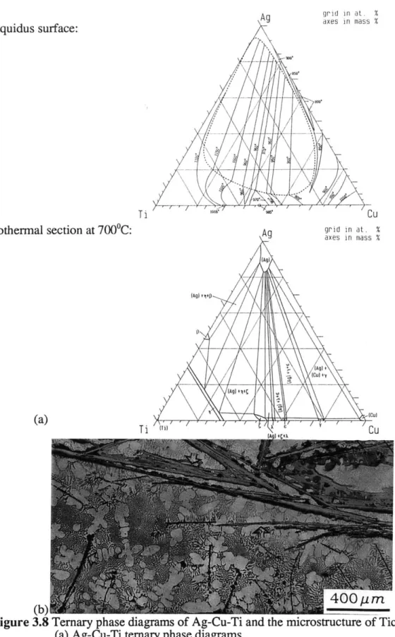
Fractograph of ABRASIVE TECH's MSL grinding wheel Ternary phase diagrams of Ag-Cu-Ti and the microstructure of Ticusil
(a) Ag-Cu-Ti ternary phase diagrams
(b) Microstructure of Ticusil brazing at 8750C* 30minutes
Fractographs of Ticusil after tensile test and grinding test (a) Fractograph of Ticusil after tensile test
(b) Fractograph of Ticusil MSL grinding wheel after grinding test Fractograph of 70Cu-21Sn-9Ti (wt%) after tensile test
The DSC analysis of 70Cu-2lSn-9Ti (wt%), heating cycle The SEM analysis of 70Cu-21Sn-9Ti (wt%), 880*C* 30minutes (a) The morphology of 70Cu-2lSn-9Ti
(b) The dot mapping of C, Ti, Sn, and Cu Wetting angle measurement installations Wetting angle measurement test samples
41 41 43 44 44 45 45 46 47 48 48 49 50 50
Figure 3.15: Figure 3.16: Figure 3.17: Figure 3.18: Figure 3.19: Figure 4.1: Figure 4.2: Figure 4.3: Figure 4.4: Figure 4.5: Figure 4.6: Figure 4.7: Figure 4.8: Figure Figure Figure Figure 4.9: 4.10: 4.11: 4.12: Figure 4.13: Figure 4.14: Figure 4.15: Figure 4.16:
Time dependent wetting angle measurement for 70Cu-2lSn-9Ti (wt%) at 9000C
Temperature dependent wetting angle for 70Cu-21Sn-9Ti (wt%) and Ticusil (Ag-Cu eutectic + 4.5wt% Ti) on polished graphite surface The change of wetting angle with various Ti contents at 920"C Fractographs of 70Cu-2lSn-9Ti (wt%) after 10 thermal cycles Fractographs of Ticusil after 10 thermal cycles
The process of finite element analysis
The morphology of the nodes and elements in the analysis
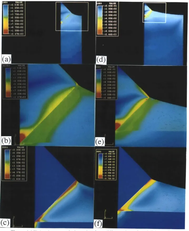
The comparison between the engineering stress-strain curve and the true stress-strain curve of an elastic-linear work hardening material Finite element analysis results of two different size ratio cooling from 900"C: (a) (b) (c) and (d) (e) (f)
The finite element analysis results of diamond/braze/(SS304) combinations
(a)(b) diamond/Cu braze/Cu disk combination
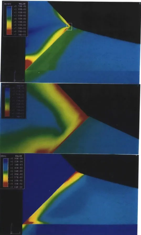
(c)(d) diamond/Cu braze/200gm Cu interlayer/SS304 Combination Finite element analysis of the MSL bond with 1 mm and 3 mm Cu interlayer
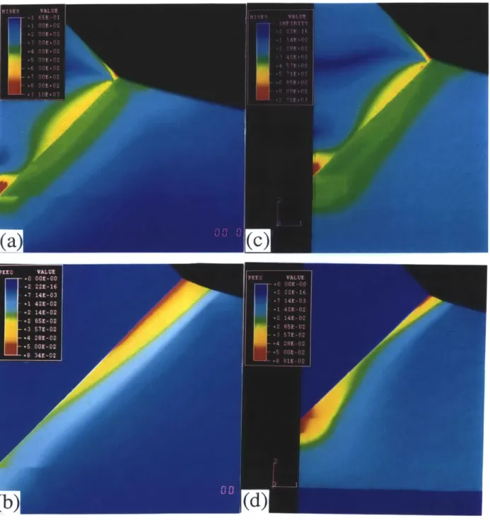
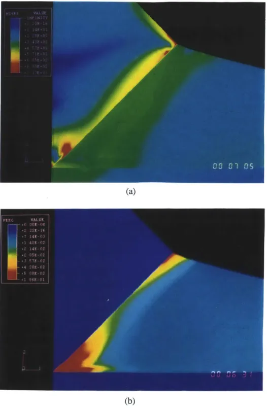
The analysis of diamond/i pm TiC/Cu braze/SS304 combination The analysis result of a 50gm crack at the bottom interface (a) Mises stress distribution (b) PEEQ distribution
The equivalent plastic strains for different brazes (a) Cu (b) Ni (c) Al The accumulated plastic strain distributions in an octagonal cone of the diamond grit
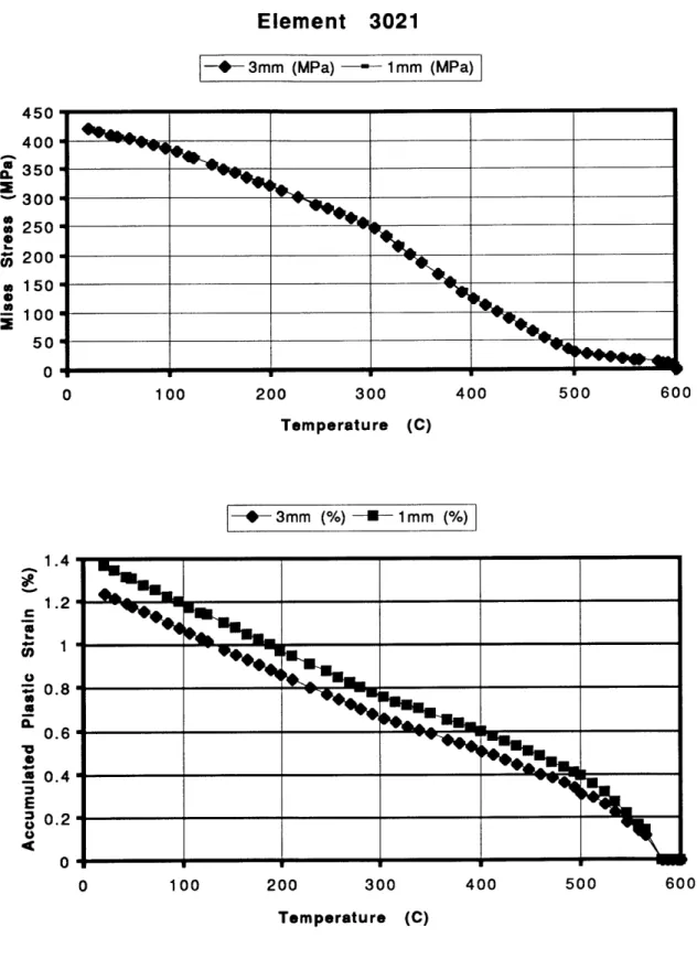
(a) lower braze alloy level (b) higher braze alloy level All stress components obtained from the finite element analysis The change of the Mises stress and the equivalent plastic strain with temperature in element 3021
The equivalent pressure stress of a two-layer braze
(a) Ni/Cu two-layer braze (b) Cu/Ni two -layer braze The SEM backscattered image in the diamond-Cu/Sn/Ti braze interface formed by a fast cooling rate after brazing
The creep strain rates of Cu and SS304 at 200, 400, and 6000C with varied Mises equivalent stresses
The currently used thermal cycle for 70Cu-21Sn-9Ti (wt%) braze alloy 51 52 52 53 54 68 69 70 71 72 73 74 75 76 77 78 79 80 81 82 83
Figure 4.18: Figure 4.19: Figure 4.20: Figure 4.21 Figure 5.1: Figure 5.2: Figure 5.3: Figure 5.4: Figure 5.5: Figure 5.6: Figure 5.7: Figure 5.8: Figure 5.9: Figure 5.10: Figure 5.11: Figure 5.12: Figure 5.13: Figure 5.14:
The Mises stress variation during the cooling cycle for three different elements
The Mises stress variations of element 3021 with different cooling rates- 100"C/min, 10*C/min, 1PC/min, 0. 1C/min
The PEEQ and CEEQ of element 3021 for various cooling rates (a) PEEQ: accumulated plastic strain (%)
(b) CEEQ: accumulated creep strain (%)
Overview of the Mises stress distribution around the braze alloy (a) rate-independent plastic model (b) 10 0C/min
(c) 10C/min (d) 0. 10C/min
Effect on abrasive wear when second phase is varied (a) small second phase, easily removed
(b) large second phase, protection of matrix
(c) very large second phase, small abrasive channeled to matrix Test procedures in developing abrasive resistant active braze alloys The results of shear test and microhardness test for various particle
additions
The results of shear and microhardness tests for 75Cu-25Sn-lOTi-XTiC (44 micron or 4 micron) by weight, brazing at 9000C*30 minutes
The morphology of A1203 swarf after grinding test
The results of shear and microhardness tests for 75Cu-25Sn-lOTi-1OZr- 1OTiC-(0-0.7)C by weight, brazing 900*C*30 minutes The microstructure of 75Cu-25Sn-lOTi and
75Cu-25Sn-lOTi-Zr-1OTiC-0.25C by weight
The erosion and wear tests of 75Cu-25Sn-lOTi-X (by weight) braze alloy
The erosion and wear tests of 75Cu-25Sn-wTi-xZr-yC-zTiC (by weight) braze alloys
EDX analysis of 75Cu-25Sn-12.5Ti-7.5Zr-1OTiC-0.2C (by weight), 9000C*30 minutes
(a) its morphology (b) the dot mapping of Zr, Ti, Sn, and Cu DSC analysis of 77Cu-23Sn-12.5Zr-10TiC-0.2C (by weight) (a) heating cycle (b) cooling cycle
The grinding test result of six different alloys
Fractographs of 77Cu-23Sn-12.5Ti-7.5Zr-1OTiC-0.2C (by weight) MSL wheel: (a) low magnification overview, (b) fractured diamond Fractograph of a debonded surface
(a) diamond/77Cu-23Sn-IOTi (by weight)
(b) 77Cu-23Sn-12.5Ti-7.5Zr-1OTiC-0.2C (by weight)/diamond
84 85 86 87 100 101 102 103 104 105 106 107 108 109 110 111 112 113
Figure 5.15: Figure 5.16: Figure 5.17: Figure 5.18: Figure 6.1: Figure 6.2: Figure 6.3: Figure 6.4: Figure 6.5: Figure 6.6: Figure 6.7: Figure 6.8: Figure 6.9: Figure 6.10: Figure 6.11: Figure 6.12: Figure 6.13:
Fractograph of a debonded surface
Fractograph of 77Cu-23Sn-12.5Ti-7.5Zr-1OTiC-0.2C (by weight) after tensile test
The morphology of two MSLwheels used in the test (a) high density alumina grinding test
(b) green concrete grinding test
Fractographs of two MSL wheels after cutting test (a) Cu/Sn/Ti bond after 300 meters of cutting
(b) Cu/Sn/TiiZr/TiC/C bond after 411.5 meters of cutting Vapor pressure as a function of temperature
The microstructure of 91Cu-4Si-5Ti in wt%, 11500C* 30minutes
The microstructural observations of Cu/Ag/Sn/f'i active braze alloys The morphology of the interface between 70 Cu-2lSn-9Ti (wt%) and Ni
(a) Cu-Sn binary phase diagram. Arrows indicate specimen composition
(b) Specific Wear of Cu-Sn bronze
The SEM back scattered image displaying the interface between braze and Fe
The EDX analysis of the interfacial phases in wt%
The morphology of the interfaces after brazing at 900*C*30 minutes (a) 70Cu-21Sn-9Ti (wt%)/Cu interface
(b) Cu/steel interface
The morphology of 70Cu-21Sn-9Ti (wt%) and Cu two-layer structure after brazing
(a) 860*C*30 minutes (b) 8800C*30 minutes (c) 9000C*30 minutes
The microstructure of 70Cu-21Sn-9Ti (wt%) and Cu two-layer structure after brazing
(a) 860*C*30 minutes (b) 8800C*30 minutes (c) 9000C*30 minutes
The microstructure of 71.4 bronze-7.2Ti-21.4Cu (wt%) brazing at: (a) 8650C*30 minutes (b) 8800C*30 minutes (c) 9000C*30 minutes
(d) 8650C*30minutes + 900"C*30 minutes
The grinding test result of three test wheels, (1), (2) and (3) as described in section 6.3
(a) power vs. the accumulated alumina removed (b) normal force vs. the accumulated alumina removed
Weight loss of three MSL bond wheels with different braze alloys (1) 70Cu-21Sn-9Ti (wt%)
(2) 77Cu-23Sn-12.5Ti-7.5Zr-1OTiC-0.2C (by weight)
(3) Two-layer structure, 76.9 wt% 77Cu/23Sn bronze-7.7 wt% Ti 15.4 wt% pure copper powder and a 50 gm pure copper interlayer 114 114 115 116 124 124 125 126 126 127 127 128 129 130 131 132 133
Figure 8.1: The schematic diagrams displaying the modified transient liquid phase bonding of the superabrasive grits
(a) before brazing
(b) first step brazing: bonding of the superabrasive grits
(c) second step brazing: dissolution and diffusion of the coated powder into the braze alloy
List of Tables
Table 3.1: The mechanical properties of Ticusil and 70Cu-2lSn-9Ti by wt% 34 Table 3.2: Wetting angle at 30 minutes for various copper-base braze alloys 38
Table 4.1: Copper and SS304 66
Table 5.1: Physical properties of some related materials 91 Table 5.2 The cutting test result of three different wheels 98 Table 6.1: Mechanical properties of some copper/tin alloys 117 Table 6.2: EDX analysis of the copper-rich phase in 70Cu-2lSn-9Ti braze alloy 121 Table 8.1: The chemical composition of some promising active braze alloys in 140
Variable Description
A power-law creep constant
Aw normal contact area in wear test
a(Me) the activity of Me
(X coefficient of thernal expansion
b the magnitude of Burgers vector
Dc core diffusion coefficient; DC = Doc exp-(Q]RT) Def effective diffusion coefficient for power law creep
Di density of the component i
Dm measured density of the braze alloy Dt theoretical density of the braze alloy
D, lattice diffusion coefficient; D,=Doexp-(Q]RT)
d particle diameter
E Young's modulus
E_() normal strain (rate) tensor
E e(l ) elastic strain (rate) tensor
EPl(tPI) plastic strain (rate) tensor
EPI equivalent plastic strain
F total deformation tensor
Fel (FP') elastic (inelastic) deformation tensor
f yield function
feI fV the fractions of atom sites associated with core and lattice diffusion respectively
AG the change in free energy
AGr the change in free energy per unit area released by reaction of the material
g) flow potential (for the ith system) 71V liquid-vapor surface tension 7,1 solid-liquid surface tension YIV solid-vapor surface tension
Ayr the change in interfacial energy after reaction
H hardness
Ha a set of hardening parameters
h the height of sample
K a dimensionless number, Archard wear coefficient
Kic fracture toughness
shear modulus
n creep exponent
V Poisson's ratio
P normal pressure
p equivalent pressure stress
Q, QV
activation energies for core and lattice diffusion respectivelyq Mises equivalent stress
R gas constant, 8.314 J/mole0K
Rw wear resistance
O wetting angle
00 wetting angle of the liquid on the substrate absent of any reaction 0mm the smallest contact angle possible in a reactive system
density
S deviatoric stress tensor
(I. stress tensor
G, yield strength
T temperature
AT, the characteristic temperature difference which causes the onset of plastic deformation
t time
U strain energy density potential
V volume of the braze alloy
Ve the volume of material removed by erosion per unit mass impacted VW the volume of material removed by wear per unit sliding distance
v velocity
vi volume fraction of the component i
Wa the weight of the braze alloy in air Wwawr the weight of the braze alloy in water x the current spatial position
I am sincerely grateful to Professor Thomas W. Eagar for his instruction and support to complete this thesis. I also deeply appreciate Norton Company financially supporting this research, and the colleagues in the Superabrasives Department of Norton Company for their kindly help to accomplish this project: Dr. S.T. Buljan, Dr. R.M. Andrews, B.J. Miller, and D.R. Vujic. I am grateful to Wei-dong Zhuang in the Welding Laboratory of MIT giving me a lot of help in the experiments. Finally, I would like to thank my dear wife, Yunai Chou, who helps me type the draft and encourages and supports me to complete this work.
1. Introduction
With the ever increasing number of ceramic materials and superalloys in the market place, grinding is both technically and economically the number one choice when one has to consider machining these materials. It is a cutting process using tools with multiple cutting edges provided by randomly bonded abrasive grits of natural or synthetic origin which remove material at high speed, mostly under interrupted cutting conditions, and improve or modify the shape, the dimensions, and/or the surface quality of the workpiece
(Metzer, 1986; Warnecke and Wimmer, 1995).
The type of abrasive and the bonding method are two key parameters for a grinding wheel. It was not until the nineteenth century that synthetic abrasives began to replace the natural abrasives of sandstone, crocus rouge, emery, corundum, and diamond (Salmon, 1992). The synthetic abrasives were used due to the fact that natural abrasives contained many impurities and varied in quality. Synthetic abrasives, however, are pure, consistent and can be carefully controlled. The most common artificial abrasives available today, in order of their popularity, are aluminum oxide, silicon carbide, cubic boron nitride (CBN), and synthetic diamond. CBN and diamond are termed superabrasives due to their high hardness (Froes, 1995).
There are three basic bonding methods - vitrified, resinoid, and metal bond (Salmon, 1992). A vitrified bond is made of clay or feldspar which is fused at high temperature to form a glass-like structure. During the firing operation, the clay or feldspar melts surrounding the abrasive grain, bonding each grain to the next, and forming a homogeneous structure. When the wheel cools, each grain is surrounded by a hard glass-like bond which has high strength and rigidity. Resin-bonded wheels are manufactured in a very similar manner to vitrified wheels. However, the bonding medium is a thermosetting synthetic resin. There are two divisions of metal-bonded wheels: those which have been plated, and those which have been brazed. Many superabrasive wheels are made with a metal bond.
For an abrasive to function properly, it must be harder than the material being ground, and be shaped to penetrate the surface of the material to be ground and form a swarf or particulates. Based on this criterion, two superabrasives - diamond and CBN
-are very suitable materials to make grinding wheels. Diamond is suited to grind tungsten carbide, natural stone, granite, concrete, and ceramics, but unsuitable for the grinding of steels due to the very aggressive chip formation which tends to tear the diamonds from their bond. Also, it is postulated that diamond, being a carbon-based material, has an affinity for iron and suffers accelerated wear by the dissolution of the diamond into the steel,
the application of diamond at elevated temperatures (Wilks and Wilks, 1991; Malkin, 1989; Tanaka, Ikawa, and Tsuwa, 1981; Pierson, 1993). Compared with diamond, CBN is less reactive in the presence of ferrous alloys and is thermally stable at elevated temperatures (-1300'C). CBN, a more expensive superabrasive than diamond, is widely used in grinding of ferrous materials like tool steel while diamond is applied in grinding of nonferrous metals and ceramics. The application of diamond and CBN can, therefore, compliment each other.
When compared with commercially available SiC or A1203 abrasives, the
application of the superabrasives in grinding some difficult machining materials is very encouraging (Aronson, 1994; Davis and Pearce, 1995). Grinding time has been significantly reduced, surface finish is improved, and there appears to be an enhancement of surface quality. Because the superabrasives are several times harder than conventional abrasives, they last longer during grinding, often 100 times or more. Consequently, they offer the potential for improved production through better finish, greater part consistency, and tighter tolerances. Moreover, the superabrasive wheel produces excellent ground surfaces unattainable with conventional wheels, and increases fatigue strength of the material with resulting reductions in part size and weight. This unique grinding performance has such a great impact on part design that machine designers will have to change their approach significantly in the very near future (Yokogawa and Yokogawa,
1992).
Metal matrices are used to bond super hard abrasives, such as diamond and CBN. The bonds are sintered from powders or made by electroplating (Borkowski and Szymanski, 1992). The metal powder used for wheel bonding consists of various compositions of copper, tin, iron, aluminum, nickel, ...etc. The most popular is bronze powder composed of copper and tin powder with various alloy additives. But quite widespread, especially in the production of diamond wheels, is a nickel electroplated bond which deposits on the metal tool body from a suitable electroplating bath. This deposit bonds the diamond grains distributed over the wheel surface usually in the form of a single layer. One of the major disadvantages for the electroplating method is its high production cost. In order to guarantee full coverage of the diamond wheel, a huge amount of diamond must be kept in the electroplating bath, and the cost of the superabrasives is high, on the order of thousands dollars per pound. One alternative method is metal single layer (MSL) produced by brazing (Aronson, 1994).
In MSL grinding technology the cutting wheel has a steel core and a layer of diamonds which are brazed with a special braze alloy (Wiand, 1990). The first step is to mix a carbide forming substance such as Ti or Cr with the traditional braze alloy powder, and form a slurry paste with a temporary binder. Second, one applies the above coating material to a tool substrate. Third, one adds at least a monolayer of diamond particles on the coating material. Finally, the preform is brazed at a temperature sufficient to form a metal carbide on the diamond and to braze the diamond to the tool substrate.
This method is less costly than the electroplating method as much less diamond is tied up in the process. The market for metal single layer grinding technology is consistently growing and the application of MSL grinding wheels may replace some traditional grinding or machining technologies. Today, MSL grinding wheels are applied at very high cutting speeds to machine materials, such as ceramics, superalloys, and magnetic
materials, which are difficult to shape.
One of the primary challenges for MSL grinding technology is to join the diamond and the steel reliably. Brazing has a major advantage compared with many other joining processes as the base materials do not melt (Akselsen, 1992). This allows brazing to be applied to the joining of dissimilar materials which can not be joined by fusion processes due to metallurgical incompatibility. In the case of brazing, ceramic-metal joints may be obtained in two different ways: (1) indirect brazing, where the ceramic surfaces are metallized prior to brazing with conventional filler metals; and (2) direct brazing, where the filler alloys contain active elements such as titanium or zirconium (Hadian and Drew, 1994). Due to oxidation of the metallized ceramic surfaces, it may be more difficult to bond diamond by indirect brazing. The oxides of many strong carbide former such as Ti, Nb, and Cr are tenacious, and the wettability of these stable oxides is much lower than that of the diamond. Moreover, if the diamond is coated with a less reactive element such as Ni or W, the bond between the diamond and the coated material is not as strong as that of direct brazing. Therefore, the second method, direct brazing diamond to the steel perform, is to be studied in this paper.
There are several criteria that the braze alloy(s) must satisfy. First, the key issue in the direct brazing is to develop brazing filler metals which provide the required wetting and spreading on both the diamond and the steel. The braze alloy will show good meniscus shape around the diamond after brazing. Second, the braze alloy should provide reasonable ductility and wear resistance in order to extend the life of the grinding wheel. Third, the braze alloy must be chemically and/or electrochemically stripped from the steel core after the diamond wears out, so the grinding wheel can be recycled. Fourth, dimensional control of the grinding wheel should be as accurate as possible, and distortion
inexpensive in order to compete with other technologies. Generally speaking, the new braze alloy(s) should meet the following conditions:
(1) wet both the diamond and the steel. (2) provide good mechanical properties.
(3) be chemically and/or electrochemically stripped without altering the steel preform.
(4) have a low brazing temperature to reduce the distortion.
(5) be inexpensive.
The goal of this research is to develop active braze alloys fitting all the above requirements for metal single layer grinding technology.
2. Literature Review
2.1 Theory and Applications of Reactive Brazing
Many researchers have concentrated on reactive brazing for ceramic/metal joints (Chattopadhyay, Chollet, and Hintermann, 1991; Kang and Kim, 1995; Russell, Oh, and Figueredo, 1991). This is because ceramics are not wetted by most traditional filler metals, even when their surfaces are clean. Ceramics are chemically very stable, with their atoms strongly bonded to one another. Therefore, these materials will not react with and be wetted by the filler unless the latter contains an active element that can attach itself to the anionic species of the nonmetallic material. Titanium is often used as an active constituent of brazes. Less reactive elements, such as chromium, and more reactive elements, such as hafnium, are also used. Active metal joining is only effective if sufficiently high temperatures, typically above 800"C, can be used for the joining operation so that the active ingredient is able to react with the nonmetal (Humpston and Jacobson, 1993).
Wettability of the active braze alloy is the first important criterion used to choose the proper type of braze alloy. Practical problems encountered in joining two dissimilar materials are not only the thermal mismatch, which causes a significant residual stress at the interface, but the chemical compatibility among the joint components and its performance at the working temperature. The active element plays a crucial role in the braze alloy, and has a strong effect on both the chemical compatibility and performance of the braze alloy.
There are many types of commercial active braze alloys based on aluminum, silver, copper, nickel, and titanium. The type of active element in the braze alloy is determined by many factors. The active element must not react strongly with the base metal, or the activity of the active element may be decreased greatly by the formation of the intermretallic compounds. For instance, Ti is not suitable as an active element in aluminum base braze alloys, because a very stable intermetallic compound will be formed between Ti and Al. Therefore, there are suitable active element(s) for different alloys. Based on previous research, the wettability of Al base braze alloys can be enhanced by adding Mg as an active element (Russell, Oh, and Figueredo, 1991; Ip, Kucharski, and Toguri, 1993). Magnesium alloying decreases the contact angle of the molten aluminum drop because evaporation of magnesium prevents formation of a thin oxide layer at the surface of the molten drop (Kobashi, Kuno, Choh, and Shimizu, 1995). Ti is a good active element in copper or silver base braze alloys (Scott and Nicholas, 1975; Xu and Indacochea, 1994). The excellent compatibility of Ni-Cr alloys has already been utilized to fabricate abrasive tools with tungsten carbide particles by liquid phase bonding (Chattopadhyay and
and Tausch, 1975).
There are four major classes of commercially available braze alloys - Al, Ni, Ag, and Cu base alloys. Two barriers prohibit the application of Al base braze alloys in metal single layer (MSL) technology. Due to the chemical stability of aluminum, there is no commercially available binder for Al base braze alloys to form a slurry paste which is a necessary step in the MSL process. For example, Al-Si braze alloy, one of the most popular Al base braze alloys, can not wet diamond at 800*C, because it reacts with the binder. In addition to the chemical stability problem, these alloys are of low strength and wear resistance and are not suitable as a braze to fabricate monolayer diamond abrasive tools. The matrix, holding the abrasive grits, should be strong enough and should not yield under the action of the cutting force transmitted to it by the grit (Chattopadhyay and Hintermann, 1993).
On the other hand, the Ni base braze alloys have high yield strength and hardness, but most of their brazing temperatures are above 1000*C (Schwartz, 1987). Because the MSL grinding wheel is used at very high grinding speeds, the distortion of the grinding wheel becomes an important issue. One of the most effective ways to reduce distortion is to decrease the brazing temperature. It is reported that high brazing temperature can result in graphitization of the diamond and decrease its strength (Wilks and Wilks, 1991). It is preferred that the brazing temperature be less than 1000'C. Another problem encountered in application of Ni-Cr-X braze alloys is that the Cr of the Ni base braze alloy can not wet CBN (Chattopadhyay and Hintermann, 1993). This situation can not be improved by increasing either the wt% of Cr or the brazing temperature, and extension of the brazing time does not show any significant changes. Therefore, the Cr content of Ni base braze alloys is not a solution for MSL technology. Ag base braze alloys are undesirable because of their low strength and prohibitively high cost. Hence, the research in this paper is concentrated on copper active base braze alloys.
At least two commercially available copper base brazing filler metals wet diamond and CBN (Sara, 1990; Schwartz, 1989; Evens, Nicholas, and Scott, 1977). Ticusil, Cu-Ag eutectic and 4.5 wt% Ti, with a solidus of 830*C and a liquidus of 8500C is one of the most popular active copper base braze alloys applied in metal-ceramic joining (Olson, 1993; Kuzumaki, Ariga, and Miyamoto, 1990). Cu/Sn/Ti, an active braze alloy with lower ductility and higher hardness and strength than that of Ticusil, is another good choice in joining diamond or CBN to steel. In addition the wear resistance is superior. However,
Highly active titanium or zirconium can be made available at the ceramic-metal interface by hydride decomposition of a powder slurry on the ceramic surface. The application of braze alloys which contain reactive metals requires that joining be performed at a very low oxygen potential, or in a dry inert-gas atmosphere with a low dew point to prevent the reactive elements from reacting with the atmosphere (Pearsall and Eingeser,
1949). However, the active titanium or zirconium hydride will decompose into pure metal and release hydrogen gas below the brazing temperature. Vacuum brazing is a better choice than inert-gas atmosphere in preventing voids in the joints after brazing. The use of hydride can avoid oxidation of the active element powder before the process begins. Another way to avoid oxidation of the active element is to use alloy powders instead of a pure elemental powder mixture, but this will result in higher cost due to the chemical instability of the active element in the process of powder formation.
A comprehensive theory of the spreading of liquids with no chemical reactions has been developed (Howe, 1993a). Considering the fact that materials possess a free surface energy balance, the Young-Dupre equation will exist between a liquid drop and a solid
substrate:
7.1 =7 - 71V cos
e
(2.1)Here, y, %1, and y,, denote the liquid-vapor, solid-liquid and solid-vapor surface tension, respectively, and 0 is the contact angle. To apply the Young-Dupre equation to non-reactive systems, the surface tension between the molten alloy and the diamond must be measured. However, these data are scarce and are system dependent (Howe, 1993a; Keene, 1993; Nogi, Okada, Ogino, and Iwamoto, 1994; Sugihara and Okazaki, 1993). Seldom can we apply this equation to the practical situation.
In the case of a reactive brazing of diamonds, it becomes much more complex than non-reactive systems. Decrease in the contact angle over time is usually taken as evidence that the reactions are occurring between the molten drop and the diamond and that the system is not equilibrium (Loehman and Tomsia, 1994). The active element, titanium, will decrease the wetting angle drastically by producing a thin layer of reaction product, titanium carbide. In addition to reaction layer formation, a precursor film, or halo, which shows up ahead of the nominal contact line is a common phenomenon in liquid metal spreading on a solid (Xian, 1993). The presence of titanium, zirconium or hafnium in the alloy induce the formation of a precursor film, but niobium, vanadium and tantalum do not. A precursor film will not form unless the critical wetting temperature is reached. This is found to be true for Ticusil and Cu/Sn/Ti alloys. If a precursor film appears ahead of the spreading droplet, better wettability of the liquid on the solid will be expected, because the precursor
of the braze alloy. Surface diffusion, evaporation-condensation, and rapid adsorption then film overflow are proposed to explain the formation of a precursor film.
Because the reactive wetting is a kinetic process, Young's equation can not be applied. There is at present no generally accepted theory capable of describing reactive wetting satisfactorily. However, there is an equation which can describe the material transfer at the solid liquid interface. The smallest contact angle possible in a reactive system is given by (Espie, Drevet, and Eustathopoulos, 1994; Kritsalis, Drevet, Valignat, and Eustathopoulos, 1994):
cos9 =cos 0 -(Ayr) AG) (2.2)
where 00 is the contact angle of the liquid on the substrate absent of any reaction; and Ayr takes into account the change in interfacial energy. AGr is the change in free energy per unit area released by the reaction of the material contained in the "immediate vicinity of the metal/substrate interface." It is often stated that AG, represents the predominant contribution of wetting, meaning that an intense reaction is required to obtain good wetting of a liquid on a solid. However, major difficulties lie in the calculation and the experimental determination of this term. Indeed, from a theoretical point of view the coupling conditions of the time-dependent interfacial reaction with the kinetics of wetting are unknown. The thickness of the zone in the immediate vicinity of the interface involved in the reaction appears as an adjustable parameter. Moreover, a simplified thermodynamic approach can not be a useful tool in determining AG, (Wang and Lannutti, 1995). For example, considering the nonideal behaviour of the liquid melt, the reaction between the reactive element (Re) in the melt with the nonmetal (X=O, N, or C) in the ceramic (MeX ) can be generalized as follows:
V V
Re+-MeX = Re X, +-Me (2.3)
E e
where v and e are the chemical stoichiometries of the ceramics. The Gibbs energy change for the reaction is
AG= AGO(ReX,)- AG(MeX,)+ R n(
)
(2.4)where AG0(ReX,) and AG0(MeX,) are the Gibbs energy of formation of ReX, and MeX', respectively, and a(Me) and a(Re) are the activities of Me and Re in the liquid melt, respectively. For most binary metal melts, these activity data at elevated temperature are lacking, although there are many improved methods for estimating such information. For most commercial multi-component brazing alloys, activity data are difficult to find, and estimating of these data may result in large deviation from reality. One can realize from equation 2.4 that reactive wetting is not only governed by the relative stability of the reactive metal compound but is also strongly dependent on the activities of the related species. An accurate estimation requires a knowledge of the activities of the reactive elements in the braze alloy. Therefore, a rigorous evaluation of AGr for a given metal/ceramic system is at present impractical (Paulasto, Kivilahti, 1995).
2.2 Reaction Zone Formation and Its Effects on Mechanical Properties of the Joint
When diamond is joined by an active braze alloy, a reaction layer forms at the interface between the ceramic and the braze alloy. It is usually admitted that chemical reaction is beneficial in achieving strong bonding (Courbiere, 1991; Prasad and Mahajan, 1994), and it is very difficult to analyze precisely the interface because of its quite different physical and chemical properties. As a result, there are still many problems in understanding the joining mechanism (Chung and Iseki, 1991). Interfacial phenomena in joining of ceramics and metals by active braze alloys have been studied extensively (Howe, 1993ab; Fujii, Nakae, and Okada, 1993; Shaw, Miracle, and Abbaschian, 1995; Lee and Lee, 1992; Treheux, Lourdin, Mbongo, and Juve, 1994; Loehman, 1994). The mechanical properties of the brazed joint is a function of key parameters such as temperature and time. Both are important in determining reaction zone formation. Many research results show that the titanium does not wet and react with ceramics below 7000C (Xian, and Si, 1991; Nukami and Flemings, 1995). Stasyuk (1984) studying the interaction of diamond with titanium at high pressure proposed a high rate of carbide formation during the initial period and retardation of the growth rate thereafter. The rate during the initial stage of the process is determined by reaction at the interface, which is very rapid compared with the second stage. This stage leads to the formation between the diamond and titanium of a sublayer of carbide having low saturation with respect to carbon, i.e., of a carbide of composition corresponding to the lower boundary of the homogeneity region. The carbide formation process is then complicated by the diffusion of carbon
during the reaction, the non-stoichiometric carbides are formed and the number of vacant lattice points in the metalloid sublattice is decreased, which also retards the rate of transfer of carbon in the carbide. Accordingly, during the second stage of the process, the growth rate of the carbide is decreased and is rate-controlled by carbon diffusion, but the carbide becomes more stoichiometric as well as more perfect in structure. The highest rate of interaction takes place during the first few minutes of heating, and the interaction is then reduced because of the decreased rate of diffusion of carbon through the layer of carbide produced.
For diffusion controlled growth, the reaction layer thickness can be estimated by a Johnson-Mehl type equation with a time exponent, n, of 0.5 (Howe, 1993; Akselsen, 1992; Nakao, Nishimoto, and Saida, 1989; Chidambaram, Edwards, and Olson, 1994):
x= kot" exp(-
)
(2.5)RT
where t is the brazing time, ko a constant,
Q
an activation energy for diffusion, R the gas constant and T is the brazing temperature.As can be expected, the strength of a ceramic-metal joint will depend on the nature of the interfacial reaction layer and residual stresses at the interface arising from a mismatch in the coefficient of thermal expansion. A summary of factors affecting the tensile strength of ceramic to metal joints is described in Figure 2.1 (Nakao, Nishimoto, Saida, and Ohishi, 1993).
When the layer forms and grows, the joint strength increases progressively up to a maximum value for increases in the area of the interface and in the mechanical interlock effect. However, the mechanical strength of a brittle system such as the reaction layer is governed by three factors: the severity of pre-existent flaws, the minimum crack propagation resistance of the material in the vicinity of that flaw, and the associated magnitude of the local residual and imposed stresses (Evans and Lu, 1986). The microstructure at the interface often displays arrays of dislocations, and defects, presumably arising from thermal expansion mismatch between joined materials (Charim, Loehman, 1990). When the reaction layer is thin, the size and quantity of the flaws in this layer are less than those in a thicker layer, but when it becomes thicker than the optimum, defects such as a porous zone and cracks occur. The existence of porosity in the reaction layer was reported in many studies (Stoop and Ouden, 1995; Gupta, Lai, and Soo, 1995). It can result from columnar-equiaxed type of solidification structure and/or the product of reaction. Consequently, an optimal reaction layer thickness exists, as has been confirmed in many experiments (Howe, 1993; Xu, Indacochea, 1994).
It has been reported that the bond strength is limited either by plastic flow or by ductile fracture in the metal when the bond layer is thick (Dalgleish, Trumble, and Evans, 1989). Conversely, when the bond layer is thin, failure occurs in the ceramic. Conditions for failure either by rupture of the metal or by brittle cracking in the ceramic have been revealed as the operative failure modes, depending on the bond layer thickness and the yield strength. Based on the previous explanation, there are optimal process variables such as temperature and time in order to acquire the best bonding strength between diamond and the braze alloy. Finding suitable process variables for certain active braze alloys is one of the primary goals of this research.
2.3 Residual Thermal Stresses after Brazing:
In the last decade great interest has been aroused in the bonding of ceramics to metals for practical applications of ceramics. There are still several problems to be solved for ideal bonding. Thermal expansion mismatch between ceramics and metals is one of them. When the joints are bonded at elevated temperatures, thermal expansion mismatch produces a large stress concentration in the joints. This stress can cause fatal damage in the joints without any applied stresses. Hence, compensation for this mismatch is needed to obtain high strength joints (Hatakeyama, Suganuma, and Okamoto, 1986). Several methods have been developed for this purpose. For example, multilayered structures have been developed to reduce the thermal stress (Shen and Suresh, 1995; Nakao, Nishimoto, Saida, Murabe, and Fukaya, 1994; Stoop and Ouden, 1995; Srolovitz, Yalisove, and Bilello, 1995). The layered structure comprises an elastic-perfectly plastic ductile material sandwiched between two elastic brittle materials. Candidate interlayer materials are selected on the basis of their mechanical and physical properties, taking into account information provided by relevant phase diagrams. The interlayers need to be ductile and should have a low yield strength and a thermal expansion coefficient matching the material combination to be joined (Cao, Thouless, and Evans, 1988).
Functionally Graded Materials (FGMs) offer another solution to the thermal stress problem (Ravicha, 1995). The FGM system consists of a gradual change in the volume fraction of constituents from one location to the other in a component. A typical FGM structure consists of a change from fully ceramic on one side to fully metal on the other side with the intermediate regions consisting of a mixture of both constituents, varying in volume fraction with distance. Such a design would allow a gradual change in thermal expansion mismatch, minimizing the thermal stresses arising from cooling or heating. Further, metallic phases embedded in the ceramic could increase the thermal conductivity,
incompatibility, wetting problem, and manufacturing cost, these ideas are currently not available for MSL technology.
There are several reported instants in which the fracture of ceramic/metal bonds originates at the interface (He, Dalgleish, Lu, and Evans, 1988; He, and Evans, 1991). Such behavior is most likely when (1) the bond is relatively thin, such that the limit load is substantially higher than the yield strength of the metal and (2) when the bond is relatively devoid of flaws. If these conditions are achieved, it is important to understand the behavior of flaws near the interface. Three important factors are involved in the behavior of these flaws: the residual stress, the mismatch in elastic properties, and plastic flow in the metal. Residual stress exerts an influence on fracture and causes fracture in the absence of an applied load. When the interface has a sufficiently high fracture energy, failure does not occur at the interface. The major limitation on the strength concerns stress concentrations in the ceramic near the edge. These stress concentrations arise because of the elastic mismatch between the metal and the ceramic. The magnitude of the stress and of the energy release rate at edge flaws is modified by plastic relaxation and thermal expansion misfit. Two basic behaviors have been identified. For strong bonds, the edge flaws are small and the stresses are large. Plastic relaxation effects dominate. Notably, the edge failures in the ceramic near the bond can be suppressed by using a metal with a low yield strength. In this regime, expansion misfit effects, although small, are detrimental. Very different characteristics are obtained when the cracks are relatively large and the stresses small, as appropriate for the assessment of crack arrest, e.g., when the loadings are displacement dominated. In this region, the energy release rate is diminished by having large positive expansion misfit, because of the compressive residual stresses generated near the interface. In the case of diamond/braze alloy bonding, there is a huge positive expansion misfit, and a compressive force is generated in the diamond near the interface. If the bond is "strong" as described above, a low yield strength braze alloy would be preferred in MSL technology when considering the stress distribution in the diamond.
It is important to estimate the residual stresses in the MSL grinding wheel after brazing. A purely elastic model may be not suitable for this analysis, although there are analytical solutions for some simple geometries (Krishna Rao and Hasebe, 1995). This is because the braze alloy experiences plastic deformation within the process temperature range. Considering a layered composite which is composed of layer 1 of height h, (made of relatively weaker material, e.g., a metal) and layer 2 of height h2 (made of the relatively stronger material, e.g., the diamond), the thermally-induced elastic deformation in a
two-layer structure with the same thickness can be estimated by the following equations (Suresh, Giannakopoulos, and Olsson, 1994):
Plane stress model:
AT
tres8- ,(E1+E+14E E 2)
(2.6)
EIE2(a - a2)(E2+ 7E1)
Plane strain model:
A Titri" = a, [B2( +v1 - v)- BEIa I (1- 2v,) + Eca4]-45 (2.7a)
E, E 1- v2
B= 1 [(1+ v1)al - (1+v 2)a2]' [7(l )( 2)+ 1]
(1-vl-) E2 1v
x [I+ ( )21 -v22+14( )-( -1 (2.7b)
E2 l-v2 E2 l-v2
where layer 1 and layer 2 are isotropic, elastic-perfectly plastic solids of Young's moduli, El and E2, with yield strengths, ay, and ay2, coefficients of thermal expansion, a1 and a 2, and Poisson's ratios, v, and V2. AT, is the characteristic temperature difference, which
causes the onset of plastic deformation in layer 1. Substituting proper material properties into equation 2.6 and 2.7, the characteristic temperature differences of various diamond/metal combinations can be obtained as shown in figure 2.2. It is clear that plastic deformation will be formed within a 100'C temperature change for diamond/metal joint. Therefore, considering the elastic response of the braze alloy only is not pragmatic. It is essential to consider plastic deformation in estimating the residual thermal stress in the braze alloy.
In addition stress relaxation by rate-independent plastic deformation, rate-dependent plastic deformation such as creep also plays an important role in decreasing the thermal stress at the interface (Pan, 1994; Paydar, Tong, and Akay, 1994). Creep dominates the mechanical response of the braze alloy at high temperatures (above 1/2 the melting point of the material), and rate-independent plasticity, on the other hand, governs the alloy behavior at low temperatures (blow 1/3 melting point of the material). Both have no currently available analytical solutions in solid mechanics. Therefore, a finite element approach becomes the easiest way to estimate the residual stresses in grinding wheels.
The grinding process can be described as a machining process which is analogous to the milling process, using a milling cutter having thousands of very small teeth. (Salmon, 1992). Each tooth removes an extremely small chip from the surface of the workpiece material, and produces a smooth and accurate surface finish. The grinding process is very difficult to analyze and even more difficult to model due to its stochastic nature.
There are generally four types of surface interactions taking place in the grinding zone characterized as shown in figure 2.3 (Subramania, and Ramanath, 1992). The interaction between the abrasive grain and the work material depends on the grinding process variables, superabrasive geometry, and work material properties. There are three frictional interactions due to the rubbing of the swarf produced against the bond matrix in the wheel, the rubbing of the bond matrix in the wheel against the work material, and the rubbing of the swarf against the work material. Based on the above descriptions, there are three possible reasons which can result in failure of a superabrasive wheel:
(1) Fracture of the superabrasive itself:
Fracture of the superabrasive may result from a heavy load of the wheel or low quality of the superabrasives. Natural diamond contains impurities and defects. Though the diamond will not expand with increasing temperature, inclusions in the diamond will expand at a rapid rate and destroy the grain (Salmon, 1992). Because synthetic diamond and CBN have fewer inclusions and defects, they are much stronger than natural diamond.
(2) Fracture at the interface between the braze alloy and the diamond:
Debonding between the diamond and the braze alloy is related to the kinetics of interlayer formation and the residual stresses within the interface as discussed earlier. Therefore, interfacial thickness control is important and will be studied in the experiment.
(3) Failure of the braze alloy due to abrasion and/or fatigue:
Wear of the braze alloy may result from rubbing of the swarf against the bond matrix or rubbing of the bond matrix against the work material. The grinding of brake pads or concrete is a typical example of the first case. The ground particles are accumulated next to the matrix and cause wear of the bond metal. On the other hand, the grinding of rubber is an example of wear due to the rubbing of the bond matrix against the work material. The wear of the bond metal results from intimate contact and friction between the bond metal and the rubber. Consequently, rubber grinding is very abrasive. In
addition to wear of the braze alloy, fatigue may also result in failure of the braze alloy which experiences cyclic loading during grinding. If there are solidification hot cracks in the braze, they may grow due to fatigue of the braze alloy. The MSL grinding wheel can not be dressed. The braze alloy will experience increasing load transmitted from the grit due to blunting of the superabrasive's cutting edges. This can be observed during grinding, because the normal force will increase with time. Therefore, the mechanical properties of the braze alloy are an important factor in determining the wheel's life. In the case of the MSL grinding process, the braze alloy experiences high cycle fatigue in the initial stages of grinding, because the superabrasive grits are sharp. Defects in the joint play an important role in determining the fatigue strength of the joint. As they become blunt, fatigue of the braze shifts from high cycle fatigue wear to low cycle fatigue wear, and the braze alloy deforms plastically due to higher applied grinding load. In other words, the ability of the braze deformed plastically dominates its fracture behavior. High ductility of the braze alloy creates higher wear resistance in low cycle-fatigue type wear (Ikeno, Siota, Nobuki, and Nakamura, 1995). A braze alloy with low yield strength and high toughness would be preferred in MSL grinding technology, because it can absorb the plastic energy much easier than a braze with a high yield strength and low toughness. The superabrasives can, therefore, be protected by the braze alloy instead of being crushed. Both ways to improve the braze alloy will be studied in this research.
In summary, an analysis of the reason why a superabrasive wheel fails is not an easy task. It depends on many factors and must be studied case by case.
Factors affecting bonding strength
Strength near the bonding interface Residual stress
I
Strength of the reaction layer Bonding strength at interface ... -[Occurrence of defects]I
Chemical bonding strength(Bond strength between atoms) Reacted bonded area(Area of the bonding interface) Mechanical joining strength (Anchoring effect)
Factors affecting the strength of ceramic to metal joints (Nakao, Nishimoto, Saida, and Ohishi, 1993)
1 Plane Stress Model U Plane Strain Model
70 40
30
1
204 1 0' 0 11 Ag-Diamond Al-DiamondFigure 2.2 The predicted characteristic temperature differences by plane stress and plane strain model
Figure 2.1 U E S S 0 S U * o~O S I-U S S U U 1~ S 0
7
Ni-Diamond7
Cu-Diamond 01 50-Diamond wheel
2
_ Workpiece
1 3
Interactions at the grinding zone: (a) superabrsive/work interface; (b) swarf/bond interface; (c) swarf/work interface; (d) bond/work interface
(Subramania, and Ramanath, 1992). Figure 2.3
Available Braze Alloys
3.1 Documentation of the Failure Mode in MSL Grinding Wheels
To identify the failure mode of MSL grinding wheels, a grinding test was made using five inch diameter test wheels with different braze alloys. High density alumina
(99.5%) blocks with dimensions of 20.32cm*10.16cm*2.54cm were used as the grinding
material. The wheel speed was 25.4 smps (surface meter per second), the longitudinal speed was 25.4 millimeter per second, the transverse feed was 2.54 mm, and the depth of cut was 0.432 mm. The definition of wheel failure in this test is when the normal force increases to 2670 N (600 lb) and/or the grinding wheel can not grind anymore. Six braze alloys were evaluated in this test as described below:
(1) NIPLATE: This is a traditional nickel-plated diamond wheel. 40/50 mesh IMG* diamonds were used as the abrasive.
(2) NORTON: This is Norton's currently used braze alloy. Its chemical composition is 70Cu-2lSn-9Ti in wt%. 77Cu-23Sn prealloyed 325 mesh bronze powder was used with titanium hydrite. 40/50 mesh IMG* diamonds were applied as the abrasive.
(3) NORTON-S: This was developed by Norton Company at Salt Lake City. It is a nickel base braze alloy, and the brazing temperature is about 1030'C. 40/50 mesh IMG* diamonds were used as the abrasive.
(4) MIT: This was made by MIT. The chemical composition is 75Cu-25Sn- 12.5Ti-7.5Zr-1OTiC-0.2C by weight. 40/50 mesh IMG* diamonds were used as the abrasive.
(5) High Sn: Cu/Sn/Ti braze alloy with over 30 wt% tin content. 40/50 mesh IMG*
diamonds were used as the abrasive.
(6) ABR TECH: This was purchased from Abrasive Technology. The quality of diamonds is unknown.
Figure 3.1 shows the fracture surface of the nickel-plated wheel. Fracture of the diamonds is the main failure mode. Most of the diamond grits still have sharp cutting edges. This indicates that only some of the grits contribute to the grinding process. When the cutting edges of the working grits become blunt, the normal force goes up, and the failure criterion of the wheel is achieved. Because there is no meniscus shape around the diamond in the Ni-plated MSL grinding wheel, the diamond is not supported by Ni. The superabrasive grits experience most of the cutting force. Moreover, the geometry of the
diamond situated in the Ni is similar to a cantilever beam. The root of the grit supports a huge moment due to the cutting force. This will induce a high tensile stress during grinding. Therefore, many diamond grits fail at the root as shown by the arrows in Figure 3.1.
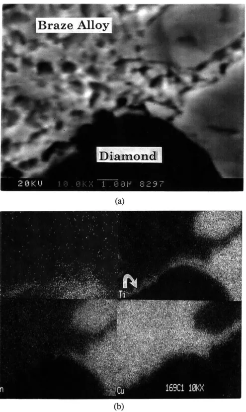
Figure 3.2 shows SEM fractographs of the currently used Cu/Sn/Ti MSL grinding wheel after grinding test. Both fractured and debonded diamonds are shown in Figure 3.2(a). There are two types of the cracks observed in the debonded and fractured diamonds. One is the cracks parallel to the diamond boundary, the other is the cracks situated in the radial direction of diamonds. The cracks parallel to the diamond boundary originate from high tensile stress in the braze alloy during grinding. This indicates that the ultimate tensile strength and/or the ductility of the braze alloy is not sufficient to support the diamond during the grinding process. Therefore, it is necessary to increase the ultimate tensile strength and/or the ductility of the braze alloy in order to retard or eliminate the formation of this type cracks.
The radial cracks, on the other hand, result from the mismatch of thermal expansion coefficients between the diamond and the braze alloy. A schematic of the cross sections of a bonded diamond grit is given in Figure 3.3. Due to the mismatch of the thermal expansion coefficients, there is a compressive stress in the diamond, and a tensile stress in the braze alloy after brazing as shown in Figure 3.3(a). In an ideal MSL bond, the diamond is tightly grasped by the braze alloy. In addition to the formation of the chemical bond between the reactive element, titanium, in the copper base braze alloy, and the diamond, the thermal expansion mismatch stresses between the diamond and the braze alloy provide an additional contribution to hold the diamond. If, however, the braze alloy can not wet the diamond very well as shown in Figure 3.3(b), thermal stress will have an adverse effect. In this case, diamond may debond and/or cracks initiate on the diamond surface due to thermal expansion mismatch. However, if the braze alloy wets the diamond too well as shown in Figure 3.3(c), the braze alloy covers most of the sharp cutting edge of the diamond. The grinding wheel will become blunt, and its grinding performance is deteriorated. The stress state in the MSL grinding wheel is very important. Therefore, a detailed analysis of thermal stress in the grinding wheel after brazing will be performed in the following chapter.
Figure 3.4 shows a fractograph of the nickel-based braze alloy developed by Norton at Salt Lake City. Both fractured and debonded diamonds are observed. The Ni-base braze alloy is very hard, over 60 HRC, and brittle. Some cracks can be observed as demonstrated by an arrow in Figure 3.4. The braze alloy should be ductile enough to absorb the thermal strain of brazing and plastic deformation during grinding. Also, it must