HAL Id: hal-02150687
https://hal.inria.fr/hal-02150687
Submitted on 7 Jun 2019
HAL is a multi-disciplinary open access
archive for the deposit and dissemination of
sci-entific research documents, whether they are
pub-lished or not. The documents may come from
teaching and research institutions in France or
abroad, or from public or private research centers.
L’archive ouverte pluridisciplinaire HAL, est
destinée au dépôt et à la diffusion de documents
scientifiques de niveau recherche, publiés ou non,
émanant des établissements d’enseignement et de
recherche français ou étrangers, des laboratoires
publics ou privés.
Framework for PHY-MAC layers Prototyping in Dense
IoT Networks using FIT/CorteXlab Testbed
Othmane Oubejja, Diane Duchemin, Matthieu Imbert, Leonardo Cardoso,
Jean-Marie Gorce
To cite this version:
Othmane Oubejja, Diane Duchemin, Matthieu Imbert, Leonardo Cardoso, Jean-Marie Gorce.
Frame-work for PHY-MAC layers Prototyping in Dense IoT NetFrame-works using FIT/CorteXlab Testbed.
CN-ERT 2019 - International Workshop on Computer and Networking Experimental Research using
Testbeds, IEEE, Apr 2019, Paris, France. pp.1-2. �hal-02150687�
Framework for PHY-MAC layers Prototyping in
Dense IoT Networks using FIT/CorteXlab Testbed
Othmane Oubejja, Diane Duchemin, Matthieu Imbert, Leonardo S. Cardoso, Jean-Marie Gorce
Univ Lyon, INSA Lyon Inria, CITI
F-69621 Villeurbanne, France [email protected]
Abstract—In this paper we present an Internet-of-Things (IoT) network implementation developed as part of the project ”Enhanced Physical Layer for Cellular IoT” (EPHYL) , using FIT/CorteXlab radio testbed. The aim of our work is to provide a customizable and open source design for IoT networks pro-totyping in a massive multi-user, synchronized and reproducible environment thanks to the hardware and software capabilities of the testbed. The massive access feature is managed by emulating several sensors per radio nodes. Two categories of network components are used in our design: a base station unit and a multi-sensor emulator unit. The components are separately hosted in dedicated and remotely accessible radio nodes. Their design features can be illustrated through a live demo, which is also reproducible as it is available for any interested reader.
Index Terms—IoT, FIT/CorteXlab, NB-IoT, Reproducibility, LPWAN, Channel Emulation, Software Defined Radio
I. INTRODUCTION
With the growing needs of rigorous and transparent sci-entific experimentation across many research fields, the im-portance of reliable testbeds is only getting more crucial in order to validate scientific models and simulations. Among these fields is wireless communication, and more particularly Internet-of-Things (IoT) which is a rapidly growing and chal-lenging domain. However, one of the challenges is robust joint hardware/software prototyping that is still lacking due to var-ious reasons (e.g. synchronization, immutable implementation solutions, unrealistic testing environment) especially for large scale experiments as required for IoT.
FIT/CorteXlab [1] radio testbed has the key properties to develop an IoT network framework, remotely and freely available for the research community. It allows to fasten the execution of large scale emulated radio experiments, as illustrated here with the evaluation of custom PHY-MAC layers derived from 3GPP Narrowband Internet of Things (NB-IoT) standard [2]. The proposed framework offers to researchers the opportunity to plug their algorithms or designs in Software Defined Radio (SDR) nodes, thus making it possible to evaluate diverse communication scenarios and perform necessary physical measurements.
II. FIT/CORTEXLABRADIOTESTBED
FIT/CorteXlab is a large scale radio testbed composed of an extensive set of SDR nodes. These latter provide substantial RF flexibility, enabling to tune the operating frequency, the
channel bandwidth, the emitted power and the waveform used to communicate. The testbed is located in a large shielded room which is partially covered with electromagnetic absorb-ing foams. Conclusively, the design of the room enables to ensure a high level of reproducibility of experimentations.
Last but not least, all SDR nodes are remotely accessible through a service interface allowing to deploy proprietary software [1].
III. DESIGNARCHITECTURE
A. Overview
We started by investigating how we can deploy an IoT-like network considering the testbed capabilities for SDR applica-tions, therefore the objective was to choose then implement key features from NB-IoT systems [2]. Our approach was to design two classes of nodes. The first class represents a Base Station (BS) and the second one a Multi-Sensor emulator (MS). In this work, a Sensor is the actual resource user. To ensure time and frequency synchronization, only USRP nodes are used, since they are connected to 8-Channel Clock Distribution modules. The wireless channels are the downlink Broadcast Channel (BCH) and the uplink, which is based on a custom and simplified version of NB-IoT PHY layer [2] [3]. Fig.1 depicts the overall network structure.
BS node O ct oc lo ck
RF Wireless Uplink Ethernet Downlink RF Wired Sync. link
MS node 2 M2 sensor emulator MS node 1 M1 sensor emulator MS node N MN sensor emulator
Fig. 1. EPHYL Network diagram.
B. Network Resources Scheduling
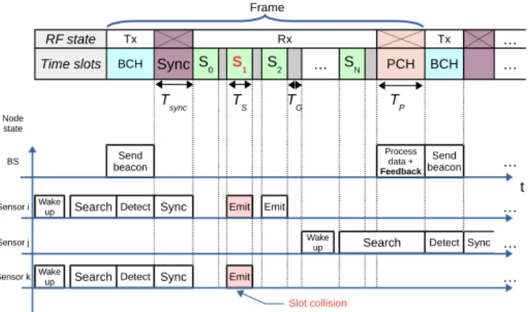
The BS follows a defined resource grid policy and a frame structure known by the sensors. At the present time, our design supports single carrier mode only. The BS starts by emitting a beacon signal (BCN) within the Broadcast Channel (BCH) which allows active Sensors to detect the BS and obtain
primary time synchronization. During the Synchronization (Sync) time slot, the Sensors compute the timing of Physical Shared Slots (Si) and decide which slots to use according to their respective access policies (regular access, Poisson distribution, etc). More details about nodes functioning are given in III-C. A guard time is used at the end of each Shared Slot to store decoded data and avoid overlapping. The final slot within the frame is a post-processing slot and is also used to generate a wired downlink message to MS nodes. This message contains information about potential slots usage and collisions as well as a decoding success score. This feedback can be used to improve the network usage by adapting the access policy and/or PHY layer parameters.
Fig.2 illustrates a functional example of the network flow during one frame, including one BS node and 3 emulated Sensors running with different parameters.
Feuille3
Page 3 Frame
RF state Tx Rx Tx …
Time slots BCH Sync … PCH BCH …
BS …
t Sensor i Search Detect Sync Emit Emit …
Sensor j Search Detect Sync …
Sensor k Search Detect Sync Emit …
Slot collision BCH Broadcast Channel Shared Channel i Detection time Slot time Post-Processing time Guard Time Tx/Rx Transmit/Receive S0 S1 S2 SN Tsync TS TG TP Node state Send beacon Process data + Feedback Send beacon Wake up Wake up Wake up Si TD Tsync TP TG
Fig. 2. Example Scenario with slot collision
C. Nodes Description
1) BS Node: The BS node is disciplined by its Scheduler which controls slots timing. On the one hand, the Sched-uler triggers the Beacon Generator during the BCH, on the other hand, it feeds the demodulation chain which starts with a Header-Payload Demultiplexer and consists of two other chains. The first one is actually a loop and concerns the header. The Channel Estimation block removes channel impairments by correlating the expected pilot sequence with the received header. The second chain purpose is to extract the payload, decode it, identify the emitters, count the decoded messages for each sensor, then broadcast the results in the wired downlink feedback channel.
2) MS Node: The MS node is composed of emulated
Sensorblocks which are connected to a complex adder. After the ”wake-up” state, each sensor generates its own packets and waits for the Sync block to trigger the local Scheduler as soon as a beacon is detected. The Access Policy block dictates to the Schedulerwhich shared slots to use based one the BS feedback and modifies PHY parameters if needed. Then, the generated waveform passes through a Channel Emulator which applies arbitrary attenuation as well as timing and frequency offsets. (See Fig.4)
BS Node
GNU Radio (Computer)
UHD Beacon Generator BS Scheduler Header/Payload Demux Channel Estimation
PHY RX formatting Data DownlinkEthernet
Trigger Header
Payload
USRP
(To MS nodes)
Fig. 3. EPHYL BS Node Block Diagram
MS Node i
GNU Radio (Computer)
UHD
Sync
Sensor 1
Data bits PHY TX(SC-FDMA)
Local Scheduler Channel Emulator Access Policy Sensor 2 Sensor 3 Sensor M .... Ethernet Downlink .... (From BS) USRP
Fig. 4. EPHYL MS Node Block Diagram
IV. DEMONSTRATION
Conducting experiments in FIT/CorteXlab requires a basic expertise. All required procedures are explained in the testbed Wiki [4] through several tutorials. Furthermore, these latter and the present framework can be carried out by any person possessing a FIT/CorteXlab account, an Internet connection and a Unix Shell. All framework components of this work are customizable and can be adjusted to users needs. The proposed demo acts as an example to show the flexibility and the modularity of the design.
V. ACKNOWLEDGMENT
This work was supported by the French National Research Agency (ANR), under grant agreement ANR-16-CE25-0002 (EPHYL project). Experiments presented in this paper were carried out using the FIT/CorteXlab testbed.
REFERENCES
[1] L. Cardoso, A. Massouri, B. Guillon, F. Hutu, G. Villemaud, T. Risset, J.M. Gorce, ”CorteXlab: A Cognitive Radio Testbed for Reproducible Experiments,”. in Proc. Wireless @ Virginia Tech Symposium, May 2014, Blacksburg, United States. 2014.
[2] Y. -. E. Wang et al., ”A Primer on 3GPP Narrowband Internet of Things,” in IEEE Communications Magazine, vol. 55, no. 3, pp. 117-123, March 2017.
[3] X. Lin, A. Adhikary and Y. -. Eric Wang, ”Random Access Preamble Design and Detection for 3GPP Narrowband IoT Systems,” in IEEE Wireless Communications Letters, vol. 5, no. 6, pp. 640-643, Dec. 2016. [4] ”FIT/CorteXlab Wiki”. [Online]. Available: https://wiki.cortexlab.fr/.