A robust sensor-selection method for P300 brain-computer interfaces.
Texte intégral
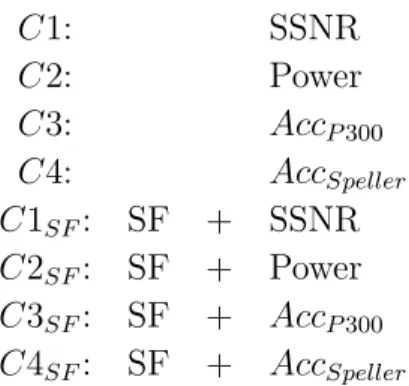
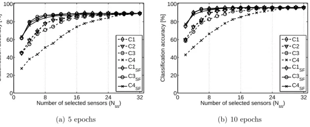
Figure


Documents relatifs
L’archive ouverte pluridisciplinaire HAL, est destinée au dépôt et à la diffusion de documents scientifiques de niveau recherche, publiés ou non, émanant des
The comparison of the presented methodology to the classical subgrid-scale model methodology on a laminar-turbulent transition test case such as the Taylor–Green vortex have also led
In the considered scenario, the actual array response vector for the interfering users differ from the array response vector used in the design of the beamformers since the
1) They are introduced axiomatically the λ-rainbow lattices. It is proved that the λ-Fuzzy subsets lattices are distributive λ-rainbow lattices and other relations of these
We show that this class contains several well known intriguing prob- lems which were heretofore known to lie in the inter- section of PLS and PPAD but were otherwise unclassifi-
Predic- tion accuracy, as measured by cross-validation (box plots) and on a very large test set (vertical lines) for different separability on the simulated data and for
Ce mémoire porte sur la relation problématique entre les structures sociales et les structures socio-politiques par le Conseil populaire de la municipale que la première cellule
Pour assurer une production durable du gombo dans le Centre de la Côte d’Ivoire, des recherches ont été menées à Bouaké, d’une part, sur l’analyse socio-économique des
