Control of Acoustics and Store Separation in a Cavity in
Supersonic Flow
by
Debashis Sahoo
B.Tech.(Hons.) in Aerospace Engineering, Indian Institute of Technology, Kharagpur, India (1998)
S.M. in Aeronautics and Astronautics, Massachusetts Institute of Technology (2000)
Submitted to the Department of Aeronautics and Astronautics in partial fulfillment of the requirements for the degree of
DOCTOR OF PHILOSOPHY at the
MASSACHUSETTS INSTITUTE OF TECHNOLOGY February 2005
@ Massachusetts Institute of Technology 2005. All rights reserved.
Certified by Certified by. Certified by Certified by Accepted by MASSACHUSETTS INSTMJE OF TECHNOLOGY
FEB 1R 2005
Department of Aeronautics and Astronautics January 26, 2005
Dr Anuradha M. A'niaswainy Senior Research Scietst pfkljechanical Engineering
D
1 Jr Ghoniei iProfess( e' 1a i n Enginering]5r James D. Paduano Principal Researc ngineer of Aeyqnautics and Astronautics
Dr K ren E. Willcox Assistant Professor
k
Aerona4icsla d Astronautics\
- '4aime Peraiie Professor f Aeronautics and Astronautics Chairman, Committee on Graduate Students
AERO
\
Control of Acoustics and Store Separation in a Cavity in Supersonic Flow by
Debashis Sahoo
Submitted to the Department of Aeronautics and Astronautics on January 26, 2005, in partial fulfillment of the
requirements for the degree of Doctor of Philosophy
Abstract
The supersonic flight community is currently faced with two cavity-under-cross-flow related problems, one being the high noise levels inside the cavity and the other being the return of a store into the cavity after being released from inside. This thesis provides a systematic framework to understand the dominant physics in both problems and to provide solutions for ameliorating the problems. For the first problem, an innovative cavity acoustics model is developed that rigorously explains the role of leading edge microjets in cavity noise suppression and predicts the magnitude of noise reduction for a given control input (that is the steady pressure at which the microjets are fired). The model is validated through comparison of its noise reduction predictions with experiments done using the Florida State University cavity and wind tunnel for different microjet pressures and under Mach 2.0 and Reynolds number 3 million flow, with the microjets being of diameter 400 microns. Based on the cavity acoustics model, optimization of the control input is performed for microjet-based noise suppression of a general cavity under external cross-flow. The resulting control strategy for the FSU cavity is that of an open loop steady microjet firing with the pressure being uniform along the leading edge. This corresponds to a noise reduction of 9 dB OASPL and 20 dB SPL at the dominant tone. The cavity also exhibits saturation in noise reduction for microjet pressures higher than 30 psig.
The second problem that the thesis is concerned with, is that of unsuccessful store drops from an external bay of an aircraft in flight. A group of researchers under the DARPA-funded HIFEX Program is currently developing an effective control mechanism to ensure safe release of a slender axi-symmetric store from a rectangular cavity under supersonic external cross-flow. The actuator being tested under this program is based on a tandem array of microjet flow injectors distributed in the spanwise direction near the leading edge of the cavity, and the control input is the steady pressure levels at which the microjets are fired. In order to optimize the control input to ensure safe store departure, a low order model that reliably predicts the trend in the store drop trajectory in the presence of microjets becomes necessary. In this thesis, a suitable low-order model is developed with separate components to predict the pitch and plunge motion of the store when it is inside the cavity, when it is passing through the shear layer at the mouth of the cavity and when it is completely outside the cavity. The model is based on slender axi-symmetric body aerodynamics, thin shear layer at the cavity mouth, high Reynolds number external cross-flow, plane shock waves associated with the microjet actuators, no-flow condition inside the cavity and inconsideration of the cavity acoustic field. The model is validated by comparing with the results of store drop experiments performed under the HIFEX Program at Mach 2.0 and 2.46 using a generic sub-scale weapons bay for different control inputs. The
store drop was observed experimentally and predicted by the model to fail when microjets were switched off and successful with microjets on. However, with an increase in microjet pressure, the store drop became unsuccessful. Finally, an optimization of the control input to ensure clean store departure for a host of drop conditions is performed using the low-order model.
Although the underlying time scales of the cavity noise and store release problems are different with the result that the two problems have distinct governing equations and so-lutions, a notable common thread for both the problems is the microjet-dependent control parameter (that is the microjet-cross-flow momentum flux ratio). Microjets introduce mo-mentum flux into the cavity noise dynamics, that damps out noise inside the cavity. The magnitude of noise reduction is saturated at higher momentum ratio (or higher microjet pressure) because of nonlinear damping effects. The addition of momentum flux also cre-ates a virtual obstruction to the external flow which gets decelerated, compressed and turns away from the cavity, thereby affecting the forces on the store and in turn its separation tra-jectory. Lower microjet momentum ratio causes the store to drop successfully while higher ratio results in its return towards the cavity because of the nonlinear interaction between the normal force and moment on the store, and store velocity and angle of attack together with the external flow turning angle.
Thesis Committee Member: Dr Anuradha M. Annaswamy Title: Senior Research Scientist of Mechanical Engineering
Thesis Committee Member: Dr Ahmed F. Ghoniem Title: Professor of Mechanical Engineering
Thesis Committee Member: Dr James D. Paduano
Title: Principal Research Engineer of Aeronautics and Astronautics
Thesis Committee Member: Dr Karen E. Willcox
Title: Assistant Professor of Aeronautics and Astronautics
Thesis Committee Member: Dr Jaime Peraire Title: Professor of Aeronautics and Astronautics
Acknowledgments
I would like to express my gratitude to my advisor, Dr Anuradha Annaswamy, for in-troducing the problem to me and for giving me unstinting guidance, advice and support throughout the execution of the thesis work and especially during the difficult times. Many thanks to my other thesis committee members (Professors Ahmed Ghoniem, Karen Will-cox, Jaime Peraire and Jim Paduano) and Prof. Edward Greitzer whose inputs during the critical stages of the thesis work were invaluable. The patience of my thesis committee, particularly while I was traversing the learning curve, is indeed commendable.
A special mention must be made of the folks at the Florida State University Fluid Mechanics Research Laboratory. Among the faculty members are Drs. Farrukh Alvi, An-janeyulu Krothapalli and Luiz Lourenco. Among the students are Ning Zhuang, Bahadir Alkislar, Brent Greska, Joe Allard, Richard Trotta, Huadong Lou and Charney Davy. Fi-nally among the staff members are Bobby Depriest and Robert Avant. They provided timely help and allowed me to use the necessary laboratory facilities for my experimental work. The warm Florida weather and the enthusiastic support of the Florida State folks also enabled me to undertake non-thesis-related activities which are not possible in the rel-atively colder Boston area. Because of all this, my trips to Florida State during summers of 2002 and 2003 will always be cherished.
In addition, I am grateful to the following graduate students at the Active Adaptive Control Laboratory and Reactive Gas Dynamics Laboratory of MIT who provided valuable inputs during various stages of the project -Jae Jeen Choi, Sungbae Park, Daehyun Wee and Youssef Marzouk. I must also thank Marie Stuppard, the Academic Program Administrator of Aeronautics and Astronautics for making my graduate life a little smoother despite me facing funding problems on a regular basis during my graduate life.
The unflinching support and encouragement of my family also helped me a great deal to grow as an individual and a researcher during my tenure at MIT.
This work was performed through a subcontract from The Boeing Company under the DARPA program "High-Frequency Excitation Active Flow Control for Supersonic Weapons Release" (Cooperative Agreement F49620-00-2-0384) and their cooperation is highly appre-ciated.
Contents
Abstract 3 Acknowledgments 5 Table of Contents 7 List of Figures 10 List of Tables 18 1 Introduction 211.1 Problem (I): Cavity Noise Under Supersonic Flow ... ... 21
1.1.1 Problem Statement ... ... 22
1.1.2 Background . . . . 23
1.1.3 Contributions of Thesis . . . . 26
1.2 Problem (II): Store Separation From Bay Under Supersonic Flow . . . . 27
1.2.1 Problem Statement . . . . 27
1.2.2 B ackground . . . . 28
1.2.3 Contributions of Thesis . . . . 29
1.3 Comparison of Cavity Noise and Store Release Problems . . . . 30
1.4 Scope of T hesis . . . . 31
2 The Cavity Acoustics Problem 33 2.1 Cavity Tones in the Absence of Microjets . . . . 33
2.1.1 Cavity Acoustics Model . . . .. 33
2.2 Effect of Microjets on Cavity Tones . . . . 37
2.2.1 Noise Suppression Using Microjets . . . .
2.2.2 Observations After Using Microjets . . . .
2.3 Cavity Acoustics Model in the Presence of Microjets . . . . 2.3.1 Uniform Control Case . . . .
2.3.2 Non-Uniform Control Case . . . .
2.4 Sum m ary . . . .
3 Optimization of Control Input for Microjet-Based Cavity Noise Suppres-sion
Problem Formulation . . . . Standard Optimal Control Solution Methods New Approach for Optimizing Control Input
3.3.1 Proper Orthogonal Decomposition . . .
3.3.2 POD-Based Optimization Procedure . .
3.3.3 RePOD-Based Optimization Procedure Experimental Results . . . .
Sum m ary . . . .
4 Store Separation From Bay Under Supersonic
4.1 Store Release Model Development . . . .
Cross-Flow
4.1.1 General Governing Equation for Two Dimensional Model . . 4.1.2 Contribution of Wavy Structures to Store Force and Moment 4.1.3 Store Motion Induced Velocity Potential . . . . 4.1.4 Force and Moment for Store Inside Cavity . . . . 4.1.5 Force and Moment When Store Crosses Shear Layer . . . . . 4.1.6 Force and Moment for Store Outside Cavity . . . . 4.2 Analysis of the Complete Store Drop . . . . 4.2.1 No microjets present . . . . 4.2.2 M icrojets Present . . . . 4.3 Experimental Validation of Store Drop Model . . . . 4.3.1 Experimental Details . . . . 4.3.2 Comparison with the Model . . . ... 4.4 Optimization of Control Input in Store Drop Setup . . . .
. . . . 38 . . . . 39 . . . . 40 . . . . 4 1 . . . . 46 . . . . 48 3.1 3.2 3.3 3.4 3.5 49 49 .. . . . 50 . . . . 50 . . . . 51 . . . . 52 . . . . 53 . . . . 54 . . . . 57 59 59 62 63 67 68 70 72 74 75 76 79 79 80 84
5 Conclusions 87 5.1 Cavity Noise Under Supersonic Flow . . . . 87 5.2 Store Separation from Bay Under Supersonic Flow . . . . 89 5.3 Limitations of the Low Order Models . . . . 90 A Order-of-Magnitude Analysis for the 2-D Uncontrolled Cavity Acoustics
Model 93
B Derivation of Green's Function in 2-D Uncontrolled Cavity Acoustics
Model 95
C Relationship Between Microjet Pressure and Associated Leading Edge
Shock Geometry 97
D Derivation of Forcing Function in 2-D Cavity Acoustics Model 99
E Derivation of Forcing Function in 3-D Cavity Acoustics Model 105
F ARX Model for Leading Edge Pressure Prediction for Cavity Noise
Con-trol 109
G Relationship Between Microjet Pressure and Shear Layer Shape, and
Plane Shock Strength 111
H Expression for Store Induced Potential and Forces For Inside Cavity 115
I Expression for Store Induced Potential and Forces For Store Portion
Par-tially Immersed in External Flow 117
J No-cavity Model for Store Outside Cavity 121
K Zero-depth-cavity Model for Store Outside Cavity 125
L Model for Store Outside But Near Cavity 129
M Model for Store Outside Cavity With Thick Shear Layer 133
List of Figures
1-1 High acoustic noise inside a cavity exposed to external cross-flow with M
2.0, Re = 3 million (based on cavity length) and L/D = 5.1. . . . . 22
1-2 Illustration of optimal closed-loop control strategy to be employed in this
thesis for cavity noise reduction. . . . . 22
1-3 Classification of models used for various types of cavity-under-external-cross-flow problem s in this thesis. . . . . 23
1-4 Different flow regimes seen by a cavity under external cross-stream. . . . . . 24
1-5 Rossiter mode feedback loop and its components. . . . .. . . . . 24
1-6 Two interpretations of the driving mechanism for cavity tones under external cross-flow . . . . 25 1-7 Possible mechanism for generation of acoustic waves inside the cavity under
external cross-flow . . . . 26 1-8 Different factors affecting the store release trajectory under supersonic
cross-flow and in the presence of microjet-based actuators. Labels 'a' and 'b'
indicate different rows of microjets located near the cavity leading edge. . . 28
2-1 Configuration of supersonic cavity flow used in the model. . . . . 34
2-2 Illustration of the assumptions behind the reduced-order cavity acoustics model. 35
2-3 Illustration of the method of images for solving the pressure perturbation field inside the cavity under external cross-flow. . . . . 36
2-4 Matching of experimental and model-predicted SPLs at the cavity leading
edge. The experiment was conducted with external flow having M = 2.0, Re
= 3 million (based on cavity length) and cavity having L/D = 5.1.
Uncer-tainty in experimental SPL was ±0.5dB and uncerUncer-tainty in frequency ±40Hz
2-5 Various passive devices used for cavity tone suppression in literature and device location relative to the cavity . . . ... . . . .38
2-6 Experimental arrangement for realizing control in the FSU cavity. The con-trol input is given in terms of the three microjet pressure banks, from bottom
to top... ... 39
2-7 Effect of leading edge shock on the external cross-flow over the cavity. . . . 40
2-8 Close-up of flow structure near the exit of microjet nozzle in the presence of external cross-flow. Adapted from Papamoschou and Hubbard [16]. . . . . . 41
2-9 Forcin 1nertia Term versus Z measured at the leading edge for 30 psig microjeterm P C pressure. External flow conditions: M = 2.0 and Re = 3 million (based on cavity length). Cavity dimension: L/D 5.1. . . . . 42
2-10 Response of 9 measured at the leading edge (LE) for 30 psig microjet pres-p sure. The initial conditions (at t = 0) correspond to uncontrolled cavity condition and were: 9 = 0.36 and 2- = 0 (arbitrary). Also, T refers to the time period corresponding to the dominant cavity tone. External flow conditions: M = 2.0 and Re = 3 million (based on cavity length). Cavity dim ension: L/D = 5.1. . . . . 43
2-11 Model prediction versus experimentally observed OASPL reduction corre-sponding to the pressure transducer location at the middle of the leading
edge. External flow conditions: M = 2.0 and Re = 3 million (based on
cavity length). Cavity dimension: L/D =- 5.1. Uncertainty in experimental OA SPL: ±i1.dB . . . . 14
2-12 Model prediction versus experimentally observed SPL spectrum correspond-ing to the pressure transducer location at the middle of the leadcorrespond-ing edge and
30 psig microjet pressure. External flow conditions: M = 2.0 and Re = 3
million (based on cavity length). Cavity dimension: L/D = 5.1. Uncertainty in experimental SPL: ±0.5dB. Uncertainty in frequency: ±40Hz. . . . 44
2-13 Experimentally observed SPL spectra corresponding to the pressure
trans-ducer location at the middle of the leading edge. The two spectra are for
the microjets-off and 30 psig microjet pressure respectively. External flow
conditions: M = 2.0 and Re = 3 million (based on cavity length). Cavity
dimension: L/D = 5.1. Uncertainty in experimental SPL: ±0.5dB.
Uncer-tainty in frequency: ±40H z. . . . . 45
3-1 Model prediction versus experimentally observed SPL spectrum (a) and OASPL reduction (b) corresponding to the pressure transducer location at the middle
of the leading edge. External flow conditions: M = 2.0 and Re = 3 million
(based on cavity length). Cavity dimension: L/D = 5.1. Uncertainty in
ex-perimental SPL: ±0.5dB. Uncertainty in frequency: ±40Hz. The microjet
pressure naming convention is based on Figure 2-6. . . . . 55 3-2 Model prediction versus experimentally observed OASPL reduction
corre-sponding to the pressure transducer location at the middle of the trailing
edge. External flow conditions: M = 2.0 and Re = 3 million (based on cav-ity length). Cavcav-ity dimension: L/D = 5.1. The uncertainty in the pressure
sensor reading was ±1.5dB and in frequency was ±40Hz. Also the initial
conditions for determining d,, were: - = 1.98 and = 0 (arbitrary). . . 56
_ at
4-1 Shock geometry outside the cavity due to application of microjet-based flow
injectors at the leading edge and upstream end. . . . .. 61
4-2 Reference frame for the general problem of a slender axi-symmetric store
falling through a cross-flow in the absence of viscosity and body forces. . . . 64
4-3 Velocity of store while inside cavity for various drop cases, with V = r.
The values of parameters used: Vo = 0.186Uo, g4|= 0.75. . . . . 69
4-4 Reference frame used when the store crosses the shear layer slip surface. . . 70
4-5 Conformal transformation required to solve for the velocity potential
4-6 Stability region predicted by the five outside-cavity models in the no-control
case. The initial conditions for the models are: Y -= - -1.63 and
1 = 2I = 0.01 with Vi = V and wi = shown in the above plot. The
uncertainty in the stability boundaries are as follows: AV1 = ±0.005, Awi
-±0.125. The cross-flow Mach number is 2.46, Reynolds number based on
store length is 4.9 million, cavity aspect ratio is 5 and store length is half of
cavity length. . . . . 75
4-7 Variation of external flow properties with C, due to application of microjets. 77
4-8 Model-predicted F and M evolution with time for different 0 when the store
passes through the shear layer. The other external flow parameters used are:
,2 - 1.818, and U-, 2 - 0.915. Also, the cross-flow uncontrolled Mach
Poo,1Uo,
number is 2.46, Reynolds number based on store length is 4.9 million, cavity
aspect ratio is 5 and store length is half of cavity length. A smoothing
function is used to remove noise in the force and moment predictions of the
m odel. . . . . 77
4-9 Different components of the model-predicted M (from Eqn. (4.37)) and their
evolution with time for different 0 when the store passes through the shear
layer. The other external flow parameters used are: P,2 =2 1.818, and U
- 0.915. Also, the cross-flow uncontrolled Mach number is 2.46, Reynolds
number based on store length is 4.9 million, cavity aspect ratio is 5 and store
length is half of cavity length. A smoothing function is used to remove noise
in the moment prediction of the model. . . . . 78
4-10 V and a^ evolution with time for different control inputs when the store passes
through the shear layer. The control inputs are specified in Table 4.1. Also, the cross-flow uncontrolled Mach number is 2.46, Reynolds number based on
store length is 4.9 million, cavity aspect ratio is 5 and store length is half of
cavity length. . . . . 79
4-11 Radius profile of the store. Here x = and a = -Also x = 0 corresponds
4-12 Store trajectory prediction (outside the cavity) versus experimental
obser-vation for: (a) no control (NOC), (b) microjet-control on (MC) and (c)
high-microjet-pressure-control (HC). Also (F,
Yc)
= 0 correspond to thein-stance when the store just exits the cavity, and increasing -fc corresponds
to the store moving away from the bay. The cross-flow Mach number is 2.46, Reynolds number based on store length is 4.9 million, cavity aspect ratio is
5 and store length is half of cavity length. The model used for trajectory
prediction is the near-cavity one, with the initial conditions given in Table 4.2. 82
4-13 Model-predicted normal force, pitching moment and state of the store
af-ter being dropped from inside the cavity to when the store either returns
back into the cavity or drops successfully in the three control cases: no
con-trol(NOC), microjet-control on(MC) and high-microjet-pressure-control(HC).
The cross-flow Mach number is 2.46, Reynolds number based on store length
is 4.9 million, cavity aspect ratio is 5 and store length is half of cavity length.
The model used for outside-cavity trajectory prediction is the near-cavity
one, with the initial conditions given in Table 4.2. A smoothing function is
used to remove noise from force and moment predictions of the model. . . . 83
4-14 Successful/Unsuccessful store drop from cavity versus microjet momentum
ratio C,. The model used for prediction of the trajectory that lies outside the
cavity is the near-cavity one. The cross-flow Mach number is 2.46, Reynolds
number based on store length is 4.9 million, cavity aspect ratio is 5 and store
length is half of cavity length. The drop conditions for this simulation are:
Yo = 1.30, oio = 0.01, Vo = -0.18,wo = 0.62 and Y1 -1.63. . . . . 84
C-1 Predicted shock trajectory based on Schetz[27] and Papamoschou and Hubbard[16].
External flow conditions: M = 2.0 and Re = 3 million (based on cavity length). 98
C-2 Shadowgraph image for the FSU cavity corresponding to 30 psig microjet
pressure. The encircled region was used for calculating the shock angle.
External flow conditions: M = 2.0 and Re = 3 million (based on cavity
D-1 Flow visualization results for the FSU cavity. Shown here are the mean transverse velocity gradient for different microjet pressures. Notation follows from Eqn. (D.7). The indicated box is the region of averaging for estimating the mean transverse microjet velocity gradient. External flow conditions:
M = 2.0 and Re = 3 million (based on cavity length). Cavity dimension: L /D = 5.1. . . . . t04
E-1 Coordinate system for the three-dimensional Green's function in the cavity acoustics m odel. . . . . 105
F-I ARX model used for predicting leading edge pressure data from trailing edge ones in the presence of several microjet pressure profiles. The model was realized using MATLAB's arx.rm function and the microjet profiles used in this study were: 50-50-50, 200-200-200 and 200-0-200 psig. The microjet pressure naming convention is based on Figure 2-6. . . . . 109
F-2 ARX model output versus experimental sensor reading for 50-50-50 psig mi-crojet pressure. The mimi-crojet pressure naming convention is based on Figure 2-6. Location of the pressure sensor: middle of the leading edge face of the cavity. Uncertainty in experimental SPL: +0.5dB. Uncertainty in frequency:
±40Hz. Also, T refers to the time period corresponding to the dominant
cavity tone. . . . 110
G-1 Flow visualization results for the FSU cavity. Shown here is the shear layer shape for different microjet momentum ratios. The shear layer shape is in-dicated by a bold line in figures (a), (b) and (c). This. line indicates the outer thickness of the shear layer (the side far from the cavity) that have non-negligible vorticity Q. Here L is the cavity length and Uoc is the ex-ternal undisturbed flow speed. The notations X' and Y' are explained in Eqn. (2.10). External flow conditions: M = 2.0 and Re = 3 million (based on cavity length). Cavity dimension: L/D = 5.1. . . . . 113
J-1 (a) Motion of a circle falling in an unbounded stream, representing far-from-cavity conditions. (b) Motion of a circle falling from a rigid wall, representing
a cavity of zero depth. (c) Motion of a circle falling from a free surface, representing store falling away from the shear layer. In all cases, the free
stream is in the X-direction. . . . . 121 M-1 Piecewise cosine wavy structure for the shear layer. The cosine component
chosen here corresponds to the X' coordinate of a point on the store surface, with X' = X'+px and the non-dimensionalization scheme is same as Eqn. (4.9).134
N-1 Reference frames (both fixed to the store and inertial) for computing F and
MI on store. . . . . 135
17
List of Tables
2.1 Dominant cavity frequency predicted by model and obtained from
experi-ments done on FSU cavity (under M = 2.0 and Re = 3 million flow). Re is
based on cavity length. . . . . 40
2.2 All possible acoustic tones in the 3-D FSU cavity under M = 2.0 and Re = 3
million flow. Re is based on cavity length. . . . . 46
4.1 Changes in external flow properties with control. Three control inputs are
considered: no control(NOC), microjet-control on(MC) and
high-microjet-pressure-control(HC). MC refers to 100-250 psig microjet pressure and HC
refers to 200-250 psig microjet pressure. The first number here refers to the
rows of microjets closest to the leading edge and the second number to the
rows at the upstream end of the cavity. Also, the cross-flow uncontrolled
Mach number is 2.46, Reynolds number based on store length is 4.9 million, cavity aspect ratio is 5 and store length is half of cavity length. . . . . 80
4.2 Initial conditions for the store trajectory analysis used in Figure 4-12. The
cross-flow Mach number is 2.46, Reynolds number based on store length is
4.9 million, cavity aspect ratio is 5 and store length is half of cavity length. 81 C. 1 Shock angles predicted by model and obtained from experiments done on
FSU cavity (under M = 2.0 and Re = 3 million flow). Re is based on cavity
length . . . . 98 G.1 Plane shock geometry for different microjet momentum ratios (C)
corre-sponding to the FSU setup. External flow conditions: M 2.0 and Re = 3
Chapter 1
Introduction
This thesis discusses two problems related to a cavity when it is exposed to a supersonic cross-flow. Problem (I) is the high noise levels observed inside the cavity, and problem (II) is the return of a store into the cavity after being released from inside. The thesis provides a systematic framework to understand the dominant physics in (I) and (II), and to provide solutions for ameliorating the problems, based on a microjet-based actuator array near the cavity leading edge. In particular, this document quantifies the extent of disruption of the dominant mechanism behind (I) because of the introduction of microjets, and the influence of the actuator on forces and moments on the store and on its drop trajectory in (II). The thesis also identifies the most relevant microjet-dependent control parameter that characterizes both (I) and (II), and provides a strategy for optimization of the control input to alleviate the two problems. The problem statement, background and the thesis contributions for (I) are outlined in Section 1.1 and for (II) in Section 1.2 in the current chapter. A brief comparison and the connection between (I) and (II) are made in Section
1.3, and the scope of this thesis is enumerated in the concluding section of this chapter.
1.1
Problem (I): Cavity Noise Under Supersonic Flow
The first problem that the thesis deals with is that of high noise levels produced when a cavity, such as the open internal bay of an aircraft, is exposed to an external cross-flow. Noise levels of around 170 dB noise have been observed in a cavity under Mach 2.0 flow [1], as illustrated in Figure 1-1. Such noise levels can potentially be harmful to the structural life of weapon systems inside a weapon bay and to landing gear deployment. The problem
170 160 U (M) 155;
(
D~150
C
145i L 140! Freq (kHz) 135 10 15 20Figure 1-1: High acoustic noise inside a cavity exposed to external cross-flow with M = 2.0, Re
= 3 million (based on cavity length) and LID = 5.1.
statement related to (I) is outlined in Section 1.1.1, its background explained in Section 1.1.2, and the contributions of this thesis towards solving (I) is given in Section 1.1.3.
1.1.1 Problem Statement
A group of researchers under the DARPA-funded HIFEX Program [1, 2, 3, 4] has, through an extensive set of experimental investigations, zeroed in on the leading edge microjets as the most effective actuator for problem (I), that uses the smallest flow rate. This thesis develops a model-based optimal closed-loop control strategy for this problem. This strategy is depicted in Figure 1-2. The pressure sensors on the cavity walls measure noise based on which the control input, which in this case is the steady pressure at which the microjets can be fired at the leading edge, is given.
-
I
shear layer structuresUp
cavity wall pressure sensor
acobstic wakes \
f0 L
p = microjet pressure optimal closed-loop (steady control input) control strate
Figure 1-2: Illustration of optimal closed-loop control strategy to be employed in this thesis for cavity noise reduction.
The model to be employed for control should necessarily be reduced-order and para-metric (say, in pp), thus allowing for closed-loop optimization. The model should also reliably capture the correct trend in the change in OASPL (Overall Sound Pressure Level) of pressure sensors with variation in control input. Along with these features, the model developed in this thesis also identifies the most relevant microjet-dependent control param-eter that characterizes the extent of disruption of the dominant mechanism behind problem (I) because of the introduction of the actuator.
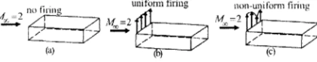
From what follows, it is expected that for an uncontrolled cavity and for a cavity with uniform spanwise microjet firing, the flow dynamics inside is two-dimensional, while the flow dynamics due to non-uniform firing is three-dimensional. Hence, the thesis first discusses a two-dimensional model valid for the no-control and uniform firing cases, and then a three-dimensional model valid for non-uniform firing. The three cases are depicted in Figure 1-3. The three-dimensional model is subsequently used for developing the appropriate
closed-AL_ -2 no F 9 unifonn firing non .. ifor m tring
Mj:4 2,V M= 2
Figure 1-3: Classification of models used for various types of cavity-under-external-cross-flow problems in this thesis.
loop optimal pressure profile. The study is limited to obtaining a steady optimal pressure profile for firing microjets.
To validate the predictions of the model, suitable tests were conducted on a cavity at the Florida State University (FSU) wind-tunnel experimental facility. These tests include flow visualization and noise measurements from pressure sensors on the cavity walls. More details of the facility are available in Zhuang et. al. [1]
1.1.2 Background
Cavity flow under the influence of an external cross-stream can exhibit the following kinds of dynamics - bulk mode (Helmholtz mode), acoustic mode (longitudinal and transverse), Rossiter mode and wake mode [5]. In general, the nature of cavity flow depends on the external flow Mach number and L/D ratio, where L is the cavity length and D is the cavity depth. It also depends on L/W (where W is the cavity width), the level of turbulence and thickness of the boundary layer in the incoming stream. However, it is more useful to look at the cavity flow in the L/D - M plane which contains the dominant factors. Such a scheme is shown in Figure 1-4. As the figure illustrates, low speed (M <- 0.1) cavities typically exhibit fluid-resonant (acoustic) mode oscillations if they are either very shallow
(L/D >~ 13) or deep (L/D <~ 0.5); otherwise they exhibit bulk mode oscillations. Higher
speed cavities exhibit Rossiter and wake modes.
Rossiter and wake modes are the most dominant types of dynamics in the typical regions of operation of the internal bay. Rossiter mode [6] has been one of the most extensively
L l-L -1 L/D very Fluid-Resonant shallow (acoustic) Z I /wake
Bulk mode /mode
(Helmholtz Rossiter
mode
Rossiter mode
- L
very deep // Fluid-Resonant (transverse, acoustic)
subsonic supersonic M
Figure 1-4: Different flow regimes seen by a cavity under external cross-stream.
studied cavity modes for both subsonic and supersonic flows and is a result of an edge-tone phenomenon. It arises when a jet (in this case, the downstream propagating shear layer disturbances) hits an edge and tones are produced. The tones propagate upstream and further excite vortical disturbances at the leading edge, which propagate downstream in the shear layer and complete a feedback loop. Figure 1-5 illustrates the feedback loop characterizing this phenomenon.
shear layer structures
-
~ ~
-- '-~~~)Shear-Layer-acoustic Waves Acoustics Trailing Edge
Figure 1-5: Rossiter mode feedback loop and its components.
The frequencies of these cavity tones depend on the cavity geometry and flow conditions and is given by Rossiter's [6] modified formula [7]:
U N - t
fN-= f L ___(1.1)M +1
1+2-M2 k
where fN is the frequency (Hz) of the Nth mode, N = 1, 2,-, p is a phase constant between the downstream propagating vortical disturbances and the upstream propagating acoustic waves, 1/k is a vorticity parameter, 7 is the specific heat ratio. p and k are
typically obtained empirically. The Rossiter's modified formula is obtained by matching of
time scales of the shear layer oscillations and acoustic waves, where 'time scales' refers to
the frequency and phase of oscillation.
There are currently two interpretations for the driving mechanism for cavity tones under
Rossiter mode and are delineated in Figure 1-6. The mechanism, given by Rossiter [6], is
the momentary flow separation at the leading edge that results in periodic shedding of
localized vortices. A literature survey, however, indicates that vortical shedding has not
been observed at all Mach numbers (only between 0.4-1.2) using current experimental
techniques. The alternative mechanism, given by Tam and Block [8], and Bilanin and
Covert [9] among others, is the Kelvin-Helmholtz instability of the free shear layer formed
at the cavity lip. The flow separation in the first interpretation and Kelvin-Helmholtz
instability in the second one are initiated by disturbances in the boundary layer at the
upstream end and sustained by excitation due to acoustic waves at the leading edge inside
the cavity. We can, however, treat the two explanations as equivalent in the sense that
vortical disturbances mentioned in the first interpretation arise due to Kelvin-Helmholtz
instabilities.
U1,U incoming
boundary layer momentary flow cnvective amplification
separation leading to ( of disturbances along
vortex shedding s ear layer
Figure 1-6: Two interpretations of the driving mechanism for cavity tones under external cross-flow.
The noise generation mechanism at the trailing edge can be attributed to the streamwise
impingement of shear layer on the trailing edge, as outlined in Figure 1-7. The impingement
results in creation of a high-pressure center at the trailing edge. The transient nature of the
impingement results in acoustic waves being produced. As explained in Tam and Block [8], these acoustic waves can be accounted for by introducing a periodic line source of monopoles
at the trailing edge. The streamwise pressure gradient due to impingement of the shear layer
on the trailing edge is: Vip' pooU2 and thus, the strength of the equivalent monopoles
is proportional to poo
In contrast to the Rossiter mode, the wake mode [10] frequency is independent of Mach
and Reynolds number. The wake mode is accompanied by coalescence of vortices shed at the
Center of high pressure
Instantaneous U-velocity profile at time i Instantaneous U-velocity profile at time +-T (T: time period)
Figure 1-7: Possible mechanism for generation of acoustic waves inside the cavity under external cross-flow.
and flow separation at the leading and trailing edges. It has not been frequently observed in practice and would not be discussed further in this document.
1.1.3 Contributions of Thesis
This thesis uses the framework of Tam and Block [8] and Bilanin and Covert [9] to develop a low order parametric model for the Rossiter tones. An order-of-magnitude analysis per-formed on the Navier-Stokes equations determines the simplified governing equation for the cavity acoustics, which is the wave equation, similar to Refs. [8, 9}. The solution of this equation is determined by the techniques of Green's function, method of images and proper orthogonal decomposition. The first two solution techniques are similar to Refs. [8, 9] and the last method is a contribution of this thesis. This document also proposes an original technique of incorporating the effect of microjets as an actuator in suppressing the cavity tones. The most relevant microjet-dependent control parameter for the cavity noise reduc-tion problem, identified by this thesis, is the microjet-external-flow momentum flux ratio. The thesis also identifies the underlying mechanism, based on microjet injection, by which noise is suppressed inside the cavity. Using the model, this thesis predicts the magnitude of noise reduction inside the cavity for a given microjet pressure distribution that is validated by experiments performed at the Florida State University wind tunnel [1]. In addition, the thesis develops a strategy for optimizing the microjet-based control -input for noise reduction inside the cavity.
1.2
Problem (II): Store Separation From Bay Under
Super-sonic Flow
In addition to high noise inside a cavity under external cross-flow, the aircraft industry is faced with problem (II), i.e. it has been observed that a store, when released from an internal aircraft bay, can return back under suitable flight conditions. Instances of unsuccessful store drops under subsonic [30] and transonic [31] flows have been found in the literature. In addition, recent experiments under the DARPA-funded HIFEX Program [2, 3, 4] have illustrated the problem under supersonic flow conditions. It should be noted that unsafe store separation is a dangerous problem for an aircraft while it drops weapons from its internal bay. To ameliorate this problem, a group of researchers under the HIFEX Program is currently developing an appropriate control strategy to ensure safe release of a slender axi-symmetric store from a rectangular cavity (bay) with an external supersonic flow. The effectiveness of various flow-disrupting actuators has been studied by the group, and the most promising one is based on an array of microjet flow injectors distributed in the spanwise direction near the leading edge of the cavity. The associated control input is the steady pressure levels at which the microjets are activated. The same actuator has been shown experimentally in [2] and through a low-order model (Chapters 2-3 of this thesis) to be effective in quietening the shear layer at the cavity opening and reduction of the cavity tones. In addition, this actuator introduces shocks which in turn induce additional corrective forces and moments on the store when it is external to the bay, thereby enabling control of its trajectory for ensuring safe separation. As in section 1.1, we discuss in sections 1.2.1, 1.2.2, and 1.2.3, the problem statement for (II), its background, and the contributions of this thesis in solving (II), respectively.
1.2.1 Problem Statement
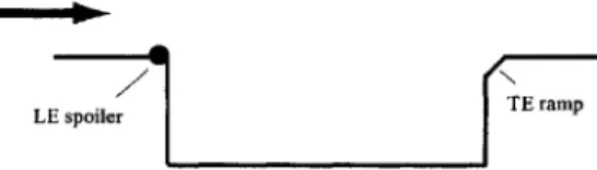
The development of an effectual control strategy for safe store separation from a cavity under cross-flow necessitates a low order model that accurately predicts the trend in the store trajectory, i.e. whether the store is ejected from the cavity safely or returns back into the cavity, under given initial drop conditions and a given control input. This trend is potentially influenced by a host of factors (Figure 1-8), including the inhomogeneous flow field generated by the wavy shear layer structures at the cavity opening, the potential
induced by the store motion, the shock waves introduced by the microjets and at the store nose, and noise inside the cavity, all of which should be incorporated in the model. What is examined in this thesis is an investigation of the forces and moments on the store due to these factors, a low-order model that captures the dominant mechanisms, and an optimization scheme for the control input to ensure safe store separation.
- resenice of
cavity walls inhomoeneous flow field dLue to wavy
shear laver stnicture
} potential induced by store motion shock due to flow injectors
Figure 1-8: Different factors affecting the store release trajectory under supersonic cross-flow and in the presence of microjet-based actuators. Labels 'a' and 'b' indicate different rows of microjets located near the cavity leading edge.
1.2.2 Background
The dynamics of a slender body separating from a rectangular cavity under a cross-flow is difficult to analyze, expensive to experiment upon and is mostly used for military ap-plications. As such, limited models are available in literature and the pertinent ones are outlined here. The problem of store release from a cavity under subsonic flow has been extensively analyzed by Shalaev, et. al. in Ref. [30]. In this paper, a low-order model of the store dynamics is derived, based on slender body potential flow theory, and results in a set of ordinary differential equations for the store motion which is analytically solvable under suitable conditions. This model is shown to predict the store trajectories observed in subsonic wind tunnel experiments. However, in the paper, neither a detailed discussion of the underlying mechanisms nor a qualitative analysis of the conditions for unsafe departure is carried out. In Ref. [31], the store separation from a cavity under transonic flow has been studied by the same authors. A similar model as in [30] is developed here too, but results in a set of nonlinear differential equations for the store trajectory that cannot be solved analytically. This model is then used to show conditions under which .unsafe store departure occurs. However, no experimental confirmation is carried out. Also as in [30], the mechanism for unsuccessful store drop is not investigated in detail. Finally in [33], the same
problem is considered in supersonic flow, with the treatment being similar to [31]. Ref. [33] predicts the conditions for unsafe store ejection and also discusses the store interaction with shock waves due to the parent body from which the store is separated. However, as before, no detailed insight into the mechanism for failure in store drop is found and no experimental validation is carried out.
An alternative approach for external store separation found in the literature [34] is based on grid testing. In this method, the store aerodynamic load at any position in the grid is assumed to be a function of only its free stream aerodynamics and the parent aircraft induced aerodynamics at that flow field position. The free stream aerodynamics is a property of the store alone while the aircraft induced aerodynamics is determined by the aircraft flow field, with the mutual interference between the aircraft and the store being considered a secondary effect. The aerodynamic loads are then fed into a six degrees-of-freedom (6 DOF) program based on Newton's laws to compute the external store release trajectory from an aircraft. An improvement over this approach is tried in a store separation problem for the SH-2G helicopter [35] in which a linear interference effect between the store and the helicopter is incorporated in the 6 DOF program. To reduce the cost of testing, a judicious combination of wind tunnel testing and CFD analysis is used. This method is validated by comparing with experimentally available store release trajectory data. However, the limitations of this approach are lack of available free stream data for all store shapes for all possible pitch angles, lack of physical insight into the problem and expensive experiments required.
1.2.3 Contributions of Thesis
The model followed in this thesis is based on the store separation work carried out for supersonic flows in Ref. [33]. By using a careful investigation of the force and moment expressions on the store obtained from the reference, we obtain a set of parametric nonlinear ordinary differential equations that enables us to identify the mechanism and, therefore, the criteria for unsafe store release from a cavity. We believe that the mechanism governing the trajectory of a store released from a cavity onto a supersonic cross-flow has not been identified before, and is therefore an import ant contribution of the thesis. A more important contribution is the extension of the model to include the effect of microjets on the store trajectory. The model identifies the most relevant microjet-dependent control parameter
(that is the microjet-cross-flow momentum flux ratio) and the underlying process by which the store trajectory is influenced, thereby predicting the microjet pressures for realizing a successful store departure. The model is also used to determine the optimal microjet pressure distribution for a clean weapon release and this control strategy is shown to agree with experimental observations made by the HIFEX group [2, 3, 4] for different supersonic Mach numbers. Finally, the model suggests better choices for the actuator parameters at some of the operating conditions.
1.3
Comparison of Cavity Noise and Store Release Problems
As the above discussions indicate, this thesis contains two distinct contributions which were presented in sections 1.1 and 1.2. Here, a brief comparison and connection between the two contributions are made. The underlying time scales of the cavity noise and store release problems are different, with the dominant frequencies being in the MHz and KHz ranges respectively. As such, the governing equations and solution tools for both problems are different. The cavity acoustics problem is governed by the damped wave equation, while the store release trajectory is governed by the Laplace Equation in the store cross-section plane. The wave equation is solved using the techniques of Green's function, method of images and proper orthogonal decomposition; the Laplace Equation by multipole expansion and conformal transformation. Further, the wave equation gives the pressure perturbation inside the cavity, which is then summed over all frequencies to give the overall sound pressure level. On the other hand, the Laplace Equation gives the velocity potential of the store which is converted to pressure using the Bernoulli's equation and then integrated over the store surface to give the normal force and moment on the store which in turn determine the store release trajectory.
A notable common thread for both the problems is the microjet-based actuation system. Microjets introduce momentum flux into the cavity noise dynamics, that manifests itself as an active damper which suppresses noise inside the cavity. The magnitude of noise reduction is saturated at higher momentum ratio because of nonlinear damping effects. Interestingly enough, the same momentum flux introduction also creates a virtual obstruction to the external flow because of which leading edge shock waves are created along with external flow deceleration, compression, and flow turning. These effects affect the normal force and
pitching moment on the store and therefore influence whether the store drops safely from the cavity or not. Both the extent of noise damping and the strength of the shock waves are determined by the shape of the micro-shock structure at the exit of the microjet nozzle. These dependencies are accurately quantified in the current document, and the strategies to optimize the control input for both the noise reduction and safe store separation problems are derived.
1.4
Scope of Thesis
This thesis outlines the development of a reduced order model for optimal control of noise inside a cavity under supersonic cross-flow, and a low order model for optimization of the control input of the drop trajectory of a store released inside a bay under supersonic flow. The actuator used in both problems is microjet-based fluid injection system placed at the cavity leading edge, with the injection being transverse to the external flow direction.
Chapter 2 discusses the development of a reduced-order model to describe the tones in the absence and presence of microjets at the leading edge. Further, two microjets-on cases are tackled: (i) microjets are fired with uniform pressure almicrojets-ong the leading edge (referred to as uniform control), and (ii) microjets are fired with pressure that varies in a pre-defined manner along the leading edge (referred to as non-uniform control). This chapter also describes the experimental arrangement used in Florida State University (FSU) for demonstrating microjet-based cavity noise reduction phenomenon.
Chapter 3 uses the three-dimensional acoustics model developed in Chapter 2 to optimize the control input for noise suppression inside a cavity under supersonic cross-flow, using microjets at the leading edge. This study is limited to the control input being a steady spanwise microjet pressure distribution. The strategy is also derived based on the proper orthogonal decomposition technique and implemented using the FSU experimental setup.
Chapter 4 deals with the second problem that the thesis is concerned with: the problem of safe store separation from a cavity under supersonic cross-flow using microjet-based actuator. This chapter outlines the development of an appropriate low order model that predicts the correct trend in the store drop trajectory. It also analyzes the low-order in terms of the store drop behavior for two cases: (I) when microjets are off, and (II) when the microjets are switched on. It then compares the low order model predictions with results
from experiments performed by the HIFEX group. Finally, it describes an optimization process to find the best control input (in terms of microjet-free-stream momentum ratio) that would ensure a successful store drop from a cavity under supersonic cross-flow.
Chapter 5 summarizes the work done and conclusions made therein. It also gives an outline for the extensions that can be made to the reduced-order models related to cavity acoustics and store release trajectory under supersonic cross-flows and their limitations.
Chapter 2
The Cavity Acoustics Problem
In this chapter, we derive a reduced-order model to describe the tones in a cavity under supersonic cross-flow. Section 2.1 describes the microjets-off case and outlines the assump-tions involved in developing the reduced-order governing equaassump-tions and the derivation of the same from the Navier-Stokes equations. Section 2.2 explains the process of suppression of tones inside a cavity under supersonic cross-flow using microjets at the leading edge. It also describes the experimental arrangement used in Florida State University (FSU) for demon-strating microjet-based cavity noise reduction phenomenon. Finally, section 2.3 outlines the derivation of the governing equations for the cavity acoustics problem with microjets-on.
2.1
Cavity Tones in the Absence of Microjets
This section discusses the development of a reduced-order model to describe the tones in a cavity under supersonic cross-flow in the absence of microjets.
2.1.1 Cavity Acoustics Model
The motivation behind the proposed reduced-order model (to be used for cavity tones control) lies in two independent pioneering works by Tam and Block [8], and Bilanin and Covert [9]. During the decade of 1970, these authors developed models predicting the frequencies of the tones in a two-dimensional rectangular cavity under external flow. The acoustic presence of the trailing edge and cavity walls was modelled by a periodic line source at the trailing edge and suitably placed images of the line sources respectively. The model agreed well with experimental results for speeds ranging from low subsonic to low supersonic
flows (M = 0.4-1.2). These studies are used as a starting point for constructing the desired reduced-order model.
Since the cavity tones are essentially a two-dimensional phenomenon, we consider a two-dimensional reduced-order model for the same. The model domain is restricted to the internal cavity volume bounded by the cavity walls and the shear layer which is at the cavity lip, as illustrated in Figure 2-1.
U1
Ua 0 D
L
Figure 2-1: Configuration of supersonic cavity flow used in the model.
Based on shadowgraph and PIV visualization studies [1], the following assumptions are made with regards to the internal cavity flow field:
(1) The shear layer separates the cavity flow field from the external supersonic stream. The supersonic flow does not expand into the cavity and there is no Prandtl-Meyer expansion fan inside the cavity.
(2) The mean convective flow inside the cavity is ignored. In practice, a reverse flow with speeds up to 40% of the external flow stream has been observed. This is neglected in the first-order proposed model.
(3) The mean static pressure is assumed to be uniform inside the cavity. In practice, the mean static pressure varies by about 15% along the streamwise direction.
(4) Static temperature and mean density is assumed to be uniform all over the cavity.
(5) Effects of gravity and viscosity are ignored.
These assumptions are outlined in Figure 2-2. Based on the assumptions, the flow inside the cavity can be considered as isentropic. Then we can apply the isentropic flow, mass and momentum conservation equations respectively to the inner cavity volume as follows:
External flow Incoming
Boundary Layer Acoustic Waves
Shear Layer: Quiescent cavity \ k separates internal
and external flows
Figure 2-2: Illustration of the assumptions behind the reduced-order cavity acoustics model.
+ V - PV = 0 (2.2)
t
DV
p i =- - Vp (2.3)
Here '-' indicates (zero-mean) perturbation quantities and '-' indicates the mean component. We use Eqns. (2.1)-(2.3) to obtain the governing equation as follows:
2 2P'=- V- -- ' + (Vp') -(' - V-') +p'V - (-' Vt') + (2.4) a2t V V)+(V/t-( Stiffness1 Stiffness2 Inertia Damping
Z
TV)
(2
InhomogeneousWe then use an order-of-magnitude analysis to identify the dominant groups (details given
in Appendix A). The governing equation obtained on keeping the dominant terms is given
by:
1 2 V2p' =0 (2.5)
with the equation valid for 0 < < 0.2, O < < Here, the subscript 'a' refers to the amplitude of the quantity.
Eqn. (2.5) can be solved using Green's function technique and method of images, similar
to Tam [8] and Covert's [9] work. Green's function method is used to derive the pressure
field in an infinitely long two-dimensional quiescent medium while the method of images is
used to account for reflection of waves at the cavity walls, as illustrated in Figure 2-3.
The governing equation for obtaining the Green's function is as follows:
d2p 2p
d2 + 0 (2.6)
... . ..
U =_ 0 Placement of source and its
L images to take care of rigid cavity walls
D (boundary conditions)
Figure 2-3: Illustration of the method of images for solving the pressure perturbation field inside the cavity under external cross-flow.
This equation is same as (B.3) in Appendix B where the solution procedure is detailed. Then the solution inside the uncontrolled cavity based on Green's function and method of images is given by:
p(X, y, t; W) ;Z H 0 L-X)2 + y2) + HM V(L + X)2 + y2) +
H (L -- x)2 + (y + 2D)2)] exp(iwt) + (-)* (2.7)
Here w is the frequency of a cavity tone in radians per second and is given from Eqn. (1.1).
It may be noted that N = 4 corresponds to the most dominant tone in the FSU cavity and
our region of interest is between N = 1 to 8 that corresponds to frequencies less than 12000
Hz. This limitation arises from the sampling frequency of the instrumentation used in the
cavity experiments. Also H(1)(-) is the first order first kind Hankel function [11].
The other unknown in Eqn. (2.7) is Q which is the strength of the source introduced in the problem and can be determined by matching the experimentally obtained spectrum with
the spectrum predicted from this model. The latter is obtained by summing the pressure
given by Eqn. (2.7) over all major Rossiter frequencies from N = 1 to 8 as follows:
8
p'(X, 7y, 0) - 1p'(X, Y, t; WN) (2-8)
N=1
The matching between the model and experimental spectra is done so as to equalize the
SPLs (Sound Pressure Levels) at the different tones and is illustrated in Figure 2-4. Apart
from the peak matching, it is clear from the figure that there is a discrepancy in frequencies
of about 10% between the values predicted by Eqn. (1.1) and the experimentally obtained
ones. The reason is that the values of p and k used in Eqn. (1.1) (that are, respectively, 0
and 0.6 for the FSU cavity) are commonly accepted values used in literature. It was further
observed that in order to match the frequencies exactly, the values of p and k need to be
in the model and the 10% difference was considered to be acceptable.
2 4 6 8 10
Frequency (kHz)
Figure 2-4: Matching of experimental and model-predicted SPLs at the cavity leading edge. The experiment was conducted with external flow having M = 2.0, Re = 3 million (based on cavity length) and cavity having LID = 5.1. Uncertainty in experimental SPL was t0.5dB and uncertainty in frequency i40Hz which is 0.8% of the dominant tone.
Now we consider the effect of assumptions (2) and (3) on the pressure field inside the cavity. The governing equation in the presence of a uniform reverse flow Ur due to pressure gradient inside the cavity is:
-Ur '-V 2 ' =0 (2.9) 49t ax We have: W w 27r(N - p) Uoo O0= -- = (2.10) Ur 8 Ur L Mo. + -1 Ur X X_
~
1+1[1~M2 j+'Y2 1 . kThis ratio is 3.2 at the dominant frequency, and so the inverse term Ur 9 is not negligible. The presence of the term Uri would change the Hankel function in Eqn. (2.7) but the change can potentially be absorbed by the acoustic source strength
Q.
In this first order model, the reverse flow effect is ignored and the pressure field given by Eqns. (2.7) and (2.8) is considered to describe the uncontrolled cavity.2.2
Effect of Microjets on Cavity Tones
In this section, we explain the process of suppression of tones inside a cavity under supersonic cross-flow using microjets at the leading edge.