Publisher’s version / Version de l'éditeur:
Vous avez des questions? Nous pouvons vous aider. Pour communiquer directement avec un auteur, consultez la
première page de la revue dans laquelle son article a été publié afin de trouver ses coordonnées. Si vous n’arrivez
Questions? Contact the NRC Publications Archive team at
PublicationsArchive-ArchivesPublications@nrc-cnrc.gc.ca. If you wish to email the authors directly, please see the first page of the publication for their contact information.
https://publications-cnrc.canada.ca/fra/droits
L’accès à ce site Web et l’utilisation de son contenu sont assujettis aux conditions présentées dans le site LISEZ CES CONDITIONS ATTENTIVEMENT AVANT D’UTILISER CE SITE WEB.
Research Report (National Research Council of Canada. Institute for Research in
Construction), 2002-05-30
READ THESE TERMS AND CONDITIONS CAREFULLY BEFORE USING THIS WEBSITE. https://nrc-publications.canada.ca/eng/copyright
NRC Publications Archive Record / Notice des Archives des publications du CNRC :
https://nrc-publications.canada.ca/eng/view/object/?id=1a138771-16e1-4718-ae85-59d1f456e5a8 https://publications-cnrc.canada.ca/fra/voir/objet/?id=1a138771-16e1-4718-ae85-59d1f456e5a8
NRC Publications Archive
Archives des publications du CNRC
For the publisher’s version, please access the DOI link below./ Pour consulter la version de l’éditeur, utilisez le lien DOI ci-dessous.
https://doi.org/10.4224/20386192
Access and use of this website and the material on it are subject to the Terms and Conditions set forth at
FIERAsystem Occupant Response (OCRM) and Occupant Evaluation
(OEVM) models theory report
Raboud, D. W.; Bénichou, N.; Kashef, A.; Proulx, G.; Hadjisophocleous, G.
V.
FIERAsystem Occupant Response (OCRM) and
Occupant Evacuation (OEVM) Models Theory Report
Raboud, D.W.; Benichou, N.; Kashef, A.; Proulx,
G.; Hadjisophocleous, G.V.
www.nrc.ca/irc/ircpubs
Research Report
FIERAsystem Occupant Response (OCRM) and Occupant
Evacuation (OEVM) Models Theory Report
Don W. Raboud, Ph.D., Noureddine Benichou, Ph.D., Ahmed Kashef, Ph.D.,
P.Eng., Guylene Proulx, Ph.D., George V. Hadjisophocleous, Ph.D.
Research Report No. RR-100
May 2002
Fire Risk Management Program
Institute for Research in Construction
National Research Council Canada
Table of Contents
Table of Contents ii List of Tables ii List of Figures ii Nomenclature iii 1. INTRODUCTION 12. OCCUPANT RESPONSE MODEL (OCRM) 2
2.1 Occupants Classifications 2
2.2 Fire States 3
2.3 Perception-Interpretation-Action (PIA) Process 4
2.3.1. Perception process 4
2.3.2. Interpretation Process 5
2.3.3. Action Process 6
2.4 Fire Detection Systems 8
2.5 Central Alarm System 10
2.6 OCRM Operation 10
2.6.1. PIA Operation 10
2.6.2. Interpretations and Actions 14
2.7 MODEL OUTPUTS 15
3. OCCUPANT EVACUATION MODEL (OEVM) 17
3.1 Model Description 17
3.2 MODEL CALCULATIONS 17
3.2.1. Average Speed Calculation 17
3.3 Calculation of Time Required to Evacuate 18 3.4 Calculation of Probability of Successful Evacuation 18
3.5 MODEL OUTPUTS 18
4. REFERENCES 20
List of Tables
Table 2.1: Probability of direct perception of fire cues (PDP). 4
Table 2.2: Interpretation levels and corresponding response delay times. 6 Table 2.3: Probability of calling fire department and activating pullbar. 7 Table 2.4. Probability of warning other occupants. 7
Table 2.5: Detection device delay levels. 8
Table 2.6: Reliabilities and delay levels of detection devices. 9
Table 2.7: Detection Device Activation Times Standard Deviations. 9
List of Figures
Figure 2.1 PIA process 2
Figure 2.2 OCRM operation flowchart 11 Figure 3.1 OVEM flowchart 19
Nomenclature
OCF occupants in the compartment of Fire Origin
CF fire’s originating compartment
OAC occupants in adjacent compartments
AC all compartments adjacent to the compartment of fire origin
OOC occupants in other compartments
OC the rest of the occupants of other building compartments
PIA perception-interpretation-action process
PPD probability of receiving a warning from direct perception of fire cues
PRWSPK probability of receiving a warning from sprinkler activation
PRWLA probability of receiving a warning from local alarms
PRWCA probability of receiving a warning from central alarm
PRWVA probability of receiving a warning from voice component of central alarm
PRWFD probability of receiving a warning from the fire department
PRWOW probability of receiving a warning from other occupants
PSPK probability of activating sprinklers
PHEAT probability of activating heat detector
PSMOKE probability of activating smoke detector
PPULLBAR probability of activating pullbar
PREMAIN probability that occupants have not yet evacuated
PC-EVAC cumulative probabilty that occupants began the evacuation process
RelCA reliability of the central alarm system
InterpCA probability that the central alarm will be interpreted correctly
POCF-CFD probability of OCF occupants calling the fire department
POAC-CFD probability of OAC occupants calling the fire department
POOC-CFD probability of OCC occupants calling the fire department
PCFD probability of the fire department will be called
TCFD time at which the fire department is called
NG number of groups
NOCC (Group) number of occupants of type Group in the compartment
V(Group) travel Speed of the occupants of type Group.
TEVAC time required for the occupants of each compartment to successfully
1. INTRODUCTION
As Canada and other countries move from prescriptive-based building codes to performance/objective-based codes, new design tools are needed to demonstrate that compliance with these new codes has been achieved. One such tool is the computer model FiRECAM™, which has been developed over the past decade by the Fire Risk Management Program of the Institute for Research in Construction at the National Research Council of Canada (NRC). FiRECAM™ is a computer model for evaluating fire protection systems in residential and office buildings that can be used to compare the expected safety and cost of candidate fire protection options.
To evaluate fire protection systems in light industrial buildings, a new computer model is being developed. This model, whose current focus is aircraft hangars and warehouses, is based on a framework that allows designers to establish objectives, select fire scenarios that may occur in the building and evaluate the impact of each of the selected scenarios on life safety, property protection and business interruption. The new computer model is called FIERAsystem, which stands for Fire Evaluation and Risk Assessment system.
FIERAsystem uses time-dependent deterministic and probabilistic models to evaluate the impact of selected fire scenarios on life, property and business interruption. The main FIERAsystem submodels calculate fire development, smoke movement through a building, time of failure of building elements and occupant response and evacuation. In addition, there are submodels dealing with the effectiveness of fire suppression systems and the response of fire departments.
The Occupant Response Model (OCRM) is used to estimate the probabilities of occupants starting to evacuate a building at different times in the event of a fire. The probabilities to commence evacuation and the delay times computed by OCRM are then used by the Occupant Evacuation Model (OEVM) which calculates occupant movement from their location to the exterior of the building. This information is used by the Expected Number of Deaths Model to estimate how many occupants in the building would perish during the fire. OCRM also calculates the probability of fire department notification and the expected notification time. In this report, the theory basis of OCRM and OEVM is described, as well as the various factors used in the models.
2. OCCUPANT RESPONSE MODEL (OCRM)
OCRM is used to estimate the probabilities of occupants starting to evacuate a building at different times in the event of a fire. The results are used later in OEVM to determine the number of occupants who have successfully evacuated. The results are also used in the Fire Department Response Model to determine the probabilities of occupants calling the fire department.
The initial modelling approach, concepts and assumptions can be found in [1]. The model calculates the time of the occupants’ response related to the information indicating the presence of a fire. The response of occupants during a fire represents a complex interaction between the occupants’ behaviour, the physical environment and the development of the fire. It is difficult to directly predict the behaviour of occupants responding to different fires. To model the general human response to fires, OCRM is based on a few processes. These processes consist of the perception of information related to the events in the development of fires; the interpretation of this information; and the
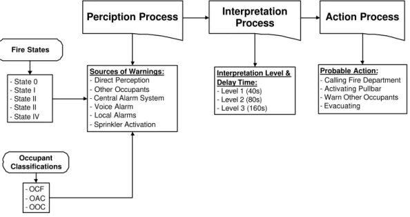
actions initiated by the decisions made from the first two processes. The process of occupant perception, interpretation and action is defined as the PIA process (Figure 2.1).
Sources of Warnings:
- Direct Perception - Other Occupants - Central Alarm System - Voice Alarm - Local Alarms - Sprinkler Activation
Probable Action:
- Calling Fire Department - Activating Pullbar - Warn Other Occupants - Evacuating
Perciption Process Interpretation
Process Action Process
Interpretation Level & Delay Time: - Level 1 (40s) - Level 2 (80s) - Level 3 (160s) Occupant Classifications Fire States - OCF - OAC - OOC - State 0 - State I - State II - State II - State IV
Figure 2.1 PIA process
2.1 Occupants Classifications
The response of occupants to a fire depends on the warning signals they perceived indicating the presence of a fire. Some of these signals are direct signals from the fire for occupants located in the vicinity of the fire, while others are automatic signals, resulting from the activation of fire and smoke detection devices. If the detection device only activates a local alarm, then only occupants in the vicinity of the fire will be notified. If the detection device, however, activates a central alarm system, then all occupants in the building will
perceive the warning. For this reason the occupant response model separates the building occupants into the following three groups.
§ Occupants in the Compartment of Fire Origin (OCF)
The occupants in the fire’s originating compartment (CF) are able to detect the fire earlier and are subjected to more severe conditions than other occupants of the building.
§ Occupants in Adjacent Compartments (OAC)
These are the occupants of all the compartments (AC) adjacent to the compartment of fire origin. These occupants take somewhat longer to become aware of the fire’s presence, but they have more time to respond than OCF occupants as it takes more time for the conditions in their compartments to become untenable.
§ Occupants in Other Compartments (OOC)
These are the rest of the occupants of other building compartments (OC). Like the occupants in the adjacent compartments, these occupants take longer to respond to the fire, but are subjected to less severe conditions (at least initially) and can respond for longer periods of time than occupants in the compartment of fire origin.
2.2 Fire States
Fire states are the times of occurrence of important events during the development of a fire [2]. Fire states are used to identify the time required for fire detection, occupant warning, response and evacuation and depend on the fire growth characteristics. There are five different fire states considered in this model:
§ Start of Fire (State 0)
The fire has started, but it is at this time undetectable by either the occupants or by the building fire detection and suppression systems.
§ Fire Cues (State I)
The fire has grown sufficiently that the occupants in the compartment of fire origin can begin to detect its presence. For purposes of the model calculations, it is assumed to be the time required for the fire plume gases to reach the ceiling.
§ Local Alarm and Smoke Detector Activation (State II)
At this stage, the fire has grown sufficiently so that the building’s local alarms and smoke detectors are able to detect the presence of fire. The fire detection model determines this time.
§ Heat Detector and Sprinkler Activation (State III)
At this stage, the fire has grown to a size that the building’s heat detectors and sprinklers are able to detect the presence of fire. The fire detection model also computes this time.
§ Flashover (State IV)
At this stage, flashover occurs in the compartment of fire. It is assumed that any occupants still remaining in the compartment of fire origin can no longer respond to the fire as it has become too intense. If the compartment is too large for flashover to occur, the time for this state is assumed to be the time when the hot ceiling gases have spread
to enough of the compartment for a sprinkler/heat detector at the furthest edge of the compartment to activate. In such a case, the conditions are assumed to be severe enough to prevent any remaining occupants from responding any further.
The fire characteristics and the detection capacity of the building determine these fire states. The occurrence of the fire states depends on different design fires. For example, non-flashover fires do not reach the state of flashover, and smouldering fires do not activate heat detectors and sprinklers. For smouldering fires, since the Fire State III may never be reached, it was assumed that the Fire State III is equal to the intervention time of the fire department.
2.3 Perception-Interpretation-Action (PIA) Process
The PIA processes involve the occupant perception of information or events related to the fire, the interpretation of the meaning and significance of that information, and the actions to be taken in response to the interpretation.
2.3.1. Perception process
The perception process relies on the occupants receiving warnings about the possible presence of the fire. In this model, there are seven ways in which the occupants can be made aware that a fire may be occurring. These seven sources of warning are:
§ Warning from direct perception of fire cues (PD)
The occupants in any compartment can be made aware of the possible presence of a fire by directly detecting cues about its presence. This can include seeing the flames, seeing the smoke, smelling the smoke, feeling the heat, hearing the fire, etc. The occupants in the compartment of fire origin have the greatest chance of detecting the fire in this manner, while those in the other compartments are less likely to notice the fire directly. The probability of direct perception, PDP, is a function of the occupant location and Fire
State. For example, the probability of direct perception at Fire State III, PDP III, is an array
of [ PDP(III, OCF), PDP (III, OAC), PDP (III, OOC)]. A total of five probabilities, from State 0
to State IV, were assumed in OCRM. Table 2.1 shows the probabilities assumed by the model of the occupants in the three compartment classifications directly perceiving the fire cues in the different fire states. These probabilities are based on expert judgement [1, 2] and were fine-tuned to arrive at reasonable evacuation times that agree with our experience and fire evacuation drills observation.
Table 2.1: Probability of direct perception of fire cues (PDP).
Occupant Fire Starts State I State II State III State IV
OCF 0 0.5 0.9 1.0 N/A
OAC 0 0 0.3 0.5 0.7
OOC 0 0 0.1 0.3 0.5
As indicated, only occupants in the compartment of fire have a chance of detecting the fire in State I. Occupants in adjacent compartments and occupants in other
compartments can begin to detect the fire at State II. At State IV (flashover), it is
assumed that occupants in the compartment of fire, if still there, will be overcome by the fire and hence can no longer detect the presence of the fire.
§ Warning from sprinkler activation (SPK) - OCF Only
If the sprinklers in the building are activated by fire, then apart from sounding the central alarm system (and possibly the voice alarm system if it is present), the occupants in the compartment of the fire origin can directly observe that the sprinklers have activated. This perception is assumed to only affect the occupants in the compartment of fire origin. The probability of receiving a warning from this source (PRWSPK) is given by
Equation 2-2 in Section 2.3.7.
§ Warning from local alarms (LA) - OCF only
Local alarms are alarms that are not connected to a central alarm system. Therefore, these alarms can activate and alert occupants to the possible presence of fire, but only for the occupants in the vicinity of the fire (i.e. the occupants in the compartment of fire origin). The probability of receiving a warning from local alarms (PRWLA) is given by
Equation 2-3 in Section 2.3.7. § Warning from central alarm (CA)
If the building’s detection devices detect the presence of fire and sound the alarm, the occupants can hear this alarm and be made aware about the possible presence of a fire. The probability of receiving a warning from central alarm (PRWCA) is given by
Equation 2-9 in Section 2.3.7.
§ Warning from voice component of central alarm (VA)
If the central alarm is activated and has a voice component, then at a specified interval after the initial alarm has sounded, a voice message will be announced to the occupants indicating the presence of fire. The probability of receiving a warning from this source (PRWVA) is given by Equation 2-10 in Section 2.3.7.
§ Warning from fire department (FD)
The fire department, after arriving at the fire scene, can begin to warn occupants in the building about the presence of the fire. Equation 2-14 in Section 2.3.7 gives the probability of receiving a warning from the fire department (PRWFD).
§ Warning from other occupants (OW)
Occupants in one compartment can be warned about the possible presence of a fire by receiving warnings from occupants of other compartments who are already aware of the fire. The probability of receiving a warning from this source (PRWOW) depends on the
probability PRWDP as explained in Section 2.3.8.
2.3.2. Interpretation Process
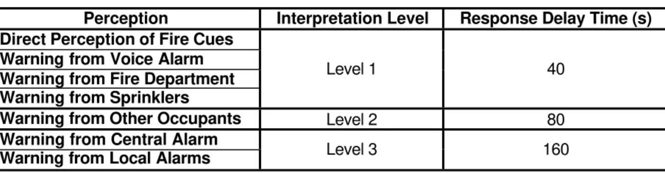
The interpretation process is directly related to the perception process. Once the information is perceived, the occupants interpret this information and proceed with different actions, which will cause a time delay before starting to evacuate. The amount of time required for this interpretation process depends on the type of perception, as some sources of warning are more likely to be immediately interpreted as indicating a fire than others. The model assumes that there are three levels of interpretation. Table 2.2 shows the three interpretation levels and corresponding delay times [1, 2] used by OCRM for each of the sources of warning discussed above. The delay times indicated in the table are meant to take into account the amount of time taken by the occupants to decide that something is happening, investigate to determine if there really is a fire, decide what to do and take some
appropriate actions before starting to evacuate. The actions that can be taken are discussed in the next section.
Table 2.2: Interpretation levels and corresponding response delay times.
Perception Interpretation Level Response Delay Time (s) Direct Perception of Fire Cues
Warning from Voice Alarm Warning from Fire Department Warning from Sprinklers
Level 1 40
Warning from Other Occupants Level 2 80
Warning from Central Alarm
Warning from Local Alarms Level 3 160
2.3.3. Action Process
The action process is closely related to the interpretation process [3]. Once a perception is interpreted as indicating a fire, the occupants may perform a number of actions before beginning the evacuation process. In OCRM, there are four possible actions:
§ Calling Fire Department: Occupants may call the fire department to alert them to the fire.
§ Activating Pullbar: OCF may activate a pullbar type device that will activate the central alarm.
§ Warning Other Occupants: Occupants may decide to warn occupants in other compartments of the fire. In this process, OCF can warn both OAC and OOC, while OAC can only warn OOC.
§ Evacuation: Evacuation is the ultimate action which occupants are assumed eventually to take.
The likelihood that occupants will take any of these actions is given by a specific probability for each of these actions that depends on the source of the original perception that was later interpreted into an action [4]. The following tables show the probabilities for taking specific actions assumed in this model [1, 2]. Table 2.3 presents the probabilities associated with the first two actions, namely, calling the fire department and activating the pullbar. The probabilities corresponding the action of warning other occupants are
Table 2.3: Probability of calling fire department and activating pullbar.
Call Fire Department Activate Pullbar Warning Source
OCF OAC OOC OCF OAC OOC
Direct Perception (State I) 0.8 N/A 0.2
Direct Perception (State II) 0.8 0.6 0.6 0.4
Direct Perception (State III) 0.8 0.6 0.6 0.6
Direct Perception (State IV) N/A 0.6 0.6 N/A
Warning from Local Alarm 0.6 N/A 0.5
Warning from Central Alarm 0.4 0.4 0.4 Done
Warning from Voice Alarm Evacuate Only
Warning From Other Occupants N/A 0.1 0.1 N/A
Warning From Fire Department Done Done
Sprinkler Activation 0.4 N/A Done
N/A
Table 2.4. Probability of warning other occupants.
Warning Source OCF Warn OAC OCF Warn OOC OAC Warn OOC
Direct Perception (State I) 0.2 0.2 N/A
Direct Perception (State II) 0.3 0.2 0.1
Direct Perception (State III) 0.5 0.2 0.1
Direct Perception (State IV) N/A N/A 0.1
Warning from Local Alarm 0.3 0.2 N/A
Warning from Central Alarm Done Done Done
Warning from Voice Alarm Evacuate Only Evacuate Only Evacuate Only
Warning From Other
Occupants N/A N/A 0.1
Warning From Fire
Department Done Done Done
Sprinkler Activation 0.2 0.1 N/A
The gray areas in Tables 2.3 and 2.4 indicate actions that are not possible or not required for specific occupants and specific perceptions. These values are assumed to be zero. A brief description of the different terms used in the gray areas:
§ “N/A”: Indicates that the occupants in the indicated compartment cannot perceive the warning source (e.g. OAC and OOC cannot directly perceive the fire cues in fire state I);
the warning source is not available to those occupants; or the OCF cannot take any action in fire state IV (flashover).
§ “Done”: Indicates that the action has already been accomplished and need not be taken (e.g. Calling the fire department after receiving a warning from the fire department); or that central alarm system has already been activated, so that the pullbar doesn’t need to be used to activate the central alarm system. It may also indicate that other occupants don’t need to be warned since everyone is assumed to already know about the fire. § Evacuate Only: After receiving a warning from the voice alarm, occupants are assumed
to be directed not to take any further actions, other than evacuation.
2.4 Fire Detection Systems
There are a number of detection devices considered in this model. Those are local and central alarms, heat detectors, sprinklers, and smoke detectors. Each of these devices is assumed to have a specific reliability that determines the probability that it will detect the fire at the appropriate time (Fire State). The location of each of these devices can also have an impact on its response time. If the devices are located outside of the compartments they will take longer to respond to the fire. Table 2.5 shows the two detection device delay levels used to reflect the effect of devices positions [1, 2].
Table 2.5: Detection device delay levels.
Detection Device Delay Level Delay Time (s)
Level 1 40
Level 2 80
The delays cause detectors to respond past the beginning of the appropriate Fire State. The individual devices and their assumed delay levels are described below.
§ Local Alarms
Local alarms exist in the compartments to sound a warning to the occupants of that compartment. Since these devices exist only within the compartments, there is no delay time to take into account for local alarms.
§ Sprinklers
Sprinklers are only considered if they are installed in the compartment of fire origin. There is therefore no delay time to take into account for sprinklers.
§ Heat Detectors
If the heat detectors are installed in the compartment of fire origin, there is no delay time for activation. On the other hand, if they are installed in adjacent compartments (e.g. in corridors) a Level 1 detection device delay before responding is assumed.
§ Smoke Detectors
If smoke detectors are installed within the compartments, no delay time is added to the detection time. Smoke detectors can also be installed in two other locations: 1) in the
corridors and HVAC systems, for which a Level 1 delay is considered, and 2) in
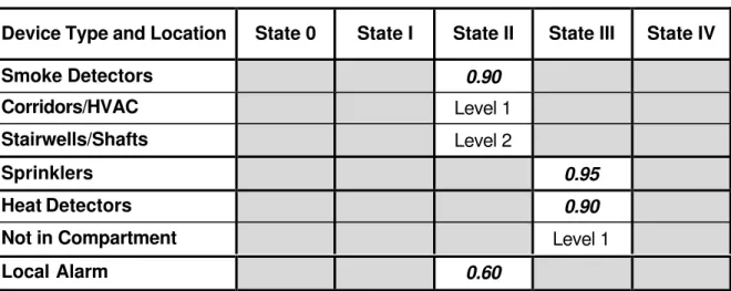
stairwells and elevator shafts, for which a Level 2 detection device delay is considered. A summary of the reliabilities and delay levels of the detection devices is given in Table 2.6.
Table 2.6: Reliabilities and delay levels of detection devices.
Device Type and Location State 0 State I State II State III State IV
Smoke Detectors 0.90
Corridors/HVAC Level 1
Stairwells/Shafts Level 2
Sprinklers 0.95
Heat Detectors 0.90
Not in Compartment Level 1
Local Alarm 0.60
To more closely approximate what actually happens, the detection devices are not considered to activate instantly and then shut off instantly at the appropriate activation time (determined by fire state and delay level). Rather, the activation time is used as a mean value around which an approximately normal probability distribution is created for when the devices will actually activate. Each device is assumed to have a standard deviation time (σ) for its activation. The standard deviations [1, 2] used by OCRM are given in Table 2.7.
Table 2.7: Detection Device Activation Times Standard Deviations. Detection Device Standard Deviation (s)
Local Alarm 10
Sprinklers 10
Heat Detectors 10
Smoke Detectors 10
A distribution is created around the mean activation time such that the total area under the distribution is equal to the probability of the device activating as determined from Table 2.6 and:
Ø ±1σ from the mean contains 68% of the overall probability of activation. Ø ±2σ from the mean contains 95% of the overall probability of activation. Ø ±3σ from the mean contains 100% of the overall probability of activation. This serves to approximate a normal distribution of the probability of the devices activating as a function of time (in seconds). These probabilities are stored in what will be referred to in upcoming discussions as the Detection Device Look-Up Table (DDLU).
2.5 Central Alarm System
A central alarm system can be activated by sprinklers, heat detectors and smoke detectors (local alarms cannot activate the central system). When one of the devices activates, the central alarm sounds throughout the building, alerting the occupants.
If the central alarm system has a voice component, then after a specified time interval, a voice message is announced to the occupants describing the situation more clearly, and urging them to evacuate.
Both the central alarm and the voice component have a specified reliability that they will operate as expected. For the OCRM model, the reliability is assumed to be 0.9 [1, 2]. As well, there is an additional factor that determines whether the alarm will be interpreted correctly. This interpretation factor is assumed to be 0.9 [1, 2] for both the central alarm and the voice component as well.
The central alarm can be monitored by the fire department. In such a case, any alarm activation will be immediately received by the fire department and the fire department will immediately begin its preparations for responding to the fire.
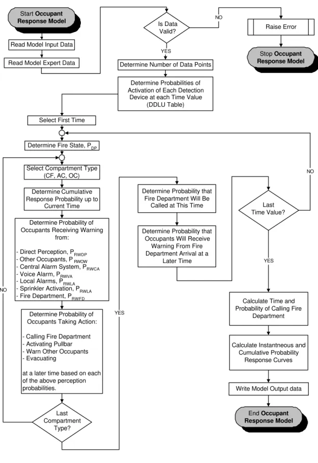
2.6 OCRM Operation
The model performs calculations at each second of the fire development (Figure 2.2). The details of the calculations are discussed below.
2.6.1. PIA Operation
Perceptions
At each time, the probability of the occupants in a given compartment perceiving each of the individual sources of warnings is calculated. The first step for each compartment type is to determine what state the fire is currently in. Then the probability of receiving a warning from each of the individual sources of warning at the current time step, Ti, is considered as
follows:
§ Receive Warning from Direct Perception (PRWDP)
The probability of receiving a warning from direct perception is determined in a two step process:
(1) The probability of direct perception for the current Fire State (PDP) is first determined
from Table 2.1. This is the probability that the fire will be perceived during the entire Fire State.
(2) To estimate the probability of perceiving the fire for each given second, the value from Table 2.1 is divided by the duration of the Fire State, to get an average probability/s for the fire state in question.
Start Occupant
Response Model
Determine Number of Data Points Read Model Input Data
Is Data
Valid? Raise Error
Stop Occupant
Response Model
NO
End Occupant
Response Model
Select First Time
Last Compartment
Type?
Calculate Instantneous and Cumulative Probability
Response Curves
Write Model Output data Calculate Time and Probability of Calling Fire
Department YES
Read Model Expert Data
Determine Fire State, P
DP
Determine Probabilities of Activation of Each Detection
Device at each Time Value (DDLU Table)
Select Compartment Type (CF, AC, OC)
Determine Cumulative Response Probability up to
Current Time
Determine Probability of Occupants Receiving Warning
from:
- Direct Perception, PRWDP - Other Occupants, PRWOW - Central Alarm System, PRWCA - Voice Alarm, PRWVA
- Local Alarms, PRWLA - Sprinkler Activation, PRWLA - Fire Department, P
RWFD
Determine Probability of Occupants Taking Action:
- Calling Fire Department - Activating Pullbar - Warn Other Occupants - Evacuating
at a later time based on each of the above perception probabilities.
NO
Last Time Value?
NO
Determine Probability that Fire Department Will Be
Called at This Time
Determine Probability that Occupants Will Receive
Warning From Fire Department Arrival at a
Later Time
YES
YES
s
in
Duration
State
Fire
P
)
(T
i DP RWDP=
P
(Eq. 2-1)§ Receive Warning from Sprinkler Activation (PRWSPK)
The probability of receiving a warning from the sprinkler activation is obtained from the DDLU Table.
Sprinkler)
,
DDLUP(T
)
T
(
P
)
T
(
i SPK i i RWSPK=
=
P
(Eq. 2-2)§ Receive Warning from Local Alarm (PR W L A)
The probability of receiving a warning from the local alarms is obtained from the DDLU Table.
Alarm)
Local
,
DDLUP(T
)
T
(
P
)
T
(
i LA i i RWLA=
=
P
(Eq. 2-3)§ Receive Warning from Central Alarm (PR W C A)
There are four ways in which the central alarm can be activated: sprinkler activation, heat detector activation, smoke detector activation, and OCF activating the pullbar. The probabilities of each of the first three events occurring (PSPK(Ti), PHEAT(Ti), and
PSMOKE(Ti)) are determined directly from the DDLU Table. The probability of the pullbar
being activated (PPULLBAR(Ti)) is a more complicated consideration, and will be discussed
more thoroughly in the next section. For now, it is enough to say that the probability that the pullbar will be activated at the current time depends on a series of perceptions and interpretations that have occurred at previous times. Once the probabilities of activating the four devices are determined, the probability of occupants receiving a warning from the central alarm can be determined. The resulting probability, PRWCA, is
the probabilistic union of the four probabilities, multiplied by the reliability of the central alarm system (RelCA), and the probability that the central alarm will be interpreted
correctly (InterpCA) i.e.
Sprinkler)
,
DDLUP(T
)
T
(
P
SPK i=
i (Eq. 2-4)Detector)
Heat
,
DDLUP(T
)
T
(
P
HEAT i=
i (Eq. 2-5)Detector)
Smoke
,
DDLUP(T
)
T
(
P
SMOKE i=
i (Eq. 2-6)]
[
)
(
T
L
Discussed
in
Section
2.3.8
L
P
PULLBAR i=
(Eq. 2-7)[
SPK i HEAT i SMOKE i PULLBAR i]
CA i CA(
T
)
P
(
T
)
P
(
T
)
P
(
T
)
P
(
T
)
*
Rel
P
=
U
U
U
(Eq. 2-8) CA i CA i RWCA(
T
)
=
P
(
T
)
*
Interp
P
(Eq. 2-9)§ Receive Warning from Voice Alarm (PRWVA)
The voice alarm activates at a fixed period of time (Voice Delay Time) later than the central alarm. The probability of receiving a warning from the voice alarm activation is the same as the probability of the central alarm activation, but delayed by the
appropriate time interval and multiplied by the probability that the central alarm will be interpreted correctly (InterpV A).
VA i
CA i
RWVA
(T
+
Voice
Delay
Time)
=
P
(T
)
*
Interp
P
(Eq. 2-10)§ Receive Warning from Fire Department (PRWFD)
There are two ways in which the fire department can be called to the fire: first they can be notified automatically if they are monitoring the central alarm system; and second they can receive a call from building occupants. The probability of automatic fire department notification is assumed to be equal to the probability of the central alarm activation, which is:
[
SPK i HEAT i SMOKE i PULLBAR i]
CA iCA
(
T
)
P
(
T
)
P
(
T
)
P
(
T
)
P
(
T
)
*
Rel
P
=
U
U
U
(Eq. 2-11)In the second scenario, the probability of occupants calling the fire department
(POCFD(Ti)) depends on perceptions and interpretations that have occurred at previous
times. It is the union of the probabilities of occupants in each compartment type calling the fire department.
)
T
(
P
)
T
(
P
)
T
(
P
)
T
(
P
OCFD i=
OCF-CFD iU
OAC-CFD iU
OOC-CFD i (Eq. 2-12)Where: POCF-CFD(Ti), POAC-CFD(Ti), POOC-CFD(Ti) are the probabilities of OCF, OAC and
OOC occupants calling the fire department respectively. How these values are determined will be discussed in the next section.
The union of the above two probabilities is the probability that the fire department will be called at the current time.
)
T
(
P
)
T
(
P
)
T
(
P
CFD i=
OCFD iU
CA i (Eq. 2-13)If the fire department is not monitoring the central alarm system, then the term PCA(Ti)
will be taken to be zero for the above calculation.
Once the fire department has been called, they will arrive on scene after a specified time interval, the Fire Department Response Time, which is either specified by the user or is computed by the Fire Department Response Model. The probability of occupants receiving a warning from the fire department is then equal to the probability that the fire department will be called, but shifted by the Fire Department Response Time.
)
T
(
P
)
Time
Response
Department
Fire
T
(
i CFD i RWFD+
=
P
(Eq. 2-14)§ Receive Warning from Other Occupants (PRWOW)
The probability of occupants receiving warnings from other occupants, (PRWOW),
depends on perceptions and interpretations that occurred at previous times, (PRWDP).
This will be discussed in more detail in the next section.
Note that PRWDP, PRWSPK, PRWLA, PRWCA, PRWVA, PRWFD and PRWOW are arrays that contain
values for each of the compartment types (OCF, OAC, OOC) even though they may depend on probabilities that are not compartment specific. The probability of the central alarm
activating (PCA), for example, does not depend on the compartment in which the occupants
are located, but their perception of that alarm (PRWCA) does. Occupants in the compartment
of fire origin cannot make any perceptions during Fire State IV (flashover), so they will not perceive the warning, while the other types of occupants (OAC and OOC) will. This notation will be used throughout; bold typeface indicates a property that contains values for each of the three compartment types.
2.6.2. Interpretations and Actions
Once a perception has been made, the occupants will go through the interpretation process and then may take a number of actions. An underscore beneath a probability will indicate that the interpretation process took place and the perception probability becomes an action probability at a later time due to the delay time needed for interpretation. For example:
)
(T
P
T
P
RWDP(
1)
⇒
RWDP 2 (Eq. 2-15)The above notation indicates that a direct perception of fire cues which occurred at time T1 is transferred to an action probability at time T2. Since, in this example, it is a direct
perception of fire cues (“Level 1” interpretation level or 40 s response delay time, Table 2.2), the time at which the corresponding actions occur, T2, is given by:
sec
40
T
T
2=
1+
(Eq. 2-16)The action which this perception leads to, is not yet determined at this point. The probabilities of each possible action being taken are determined based on Table 2.3 and Table 2.4. Once there is a probability that a perception has occurred, there is a probability that this perception can be transferred into each of the action probabilities shown in these two tables. As a result, any or all of these actions may be performed (i.e. they are not exclusive).
In general, the process is the following: If a perception has probability Pp of occuring at
time tP, it will have a probability PA C T of being transferred into an action probability at a later
time tA. The time at which the action will take place is determined from the interpretation
delay level (Table 2.2).
Time
Delay
tion
Interpreta
t
t
A=
P+
(Eq. 2-17)The probability of a specific action occurring is determined by multiplying the probability of the perception occurring by the probability of the action occuring given that the perception has occurred (PA, obtained from Tables 2.3 and 2.4), i.e.
A P A
ACT
(
t
)
P
*
P
P
=
(Eq. 2-18)The above PA C T is the probability that an action will occur based upon this one particular
perception. In general, the action may already have a probability of occurring at time tA due
to previous perceptions and interpretations of different sources of warning. In this case, the probability of the action occurring will be the probabilistic union of whatever probability is currently at time tA and the new probability calculated above for this perception. The above
)
P
*
(P
)
(t
P
)
(t
P
ACT A=
ACT AU
P A (Eq. 2-19)One further modification is required. As time progresses, occupants perceive the fire and eventually will evacuate, which results in fewer and fewer people to receive the warnings and take actions. To account for this, the action probabilities for the current perception are modified to take into account the number of occupants remaining in the compartment at the time the perception occurred. The actual action probability is multiplied by the probability that there will still be occupants in the compartment to perceive the
warning and take the appropriate actions. The probability that there will still be occupants in the compartment, PREMAIN(tP), is simply the probability that occupants have not yet
evacuated, or
)
t
(
P
1
)
t
(
P
REMAIN P=
−
C−EVAC P (Eq. 2-20) where PC-EVAC(tP) is the cumulative probabilty that occupants will have begun the evacuationprocess by the time of perception, tP. This calculation is discussed in the next section. With
PREMAIN(tP) determined, the final form of the equation becomes:
[
P
(t
)
]
[
(P
*
P
)
*
P
(
t
)
]
)
(t
P
ACT A=
ACT AU
P A REMAIN P (Eq. 2-21)This equation is applied after each perception, (at each time in each compartment), to each possible action that results from these perceptions. In this way, the actions that may occur at a later time are determined at the current time. In particular, this is how the action probabilities of calling the fire department, warning other occupants, and activating the pullbar mentioned in the previous section are determined.
2.7 MODEL OUTPUTS
OCRM determines two main pieces of information, these are: § Probabilities of Response (Start of Evacuation Process)
In the calculations above, a perception probability is transferred (interpreted) into an action probability. Several possible actions may be taken. Eventually all perceptions are assumed to be interpreted into a probability that occupants will begin to evacuate, regardless of what other actions the occupants may have decided to take. In this way, the probability that occupants in each compartment will decide to evacuate, at each moment in time, is calculated.
The probabilities calculated by the model, as discussed above, are instantaneous in the sense that they indicate the probability of evacuation starting at that instant only. A more useful way to utilize the same information is to calculate the cumulative probability, which indicates what proportion of the initial occupants have begun the evacuation process up to that point in time. The cumulative probability at each point in time (PC-EVAC(t)) can be calculated from the instantaneous probability at each point in time
(PI-EVAC(t) = PEVAC(t) as calculated above) as follows:
)
)
(T
(1
*
)
(T
)
(T
)
(T
i C-EVAC i 1 I-EVAC i 1 C-EVAC i 1EVAC
-C
=
P
−+
P
−−
P
−This illustrates that the cumulative probability at time, Ti, is calculated based solely on
information at the previous instant in time Ti-1. The cumulative probability of occupants
beginning to evacuate is calculated for each compartment type. § Time and Probability of Calling the Fire Department
The other information that the Occupant Response Model provides is the time and the corresponding probability of calling the fire department. This information is used by other models in FIERAsystem for both hazard and risk analyses. These calculations are described below.
The time at which the fire department is called is estimated based on the probability distribution of calling the fire department, PCFD. This probability, as explained above,
depends on both the occupants calling the fire department and the possibility that the fire department is monitoring the central alarm system. The single probability curve obtained contains the instantaneous values. The time at which the fire department is called (TCFD) is estimated to be the weighted average of these probability values,
weighted by the time at which they occur.
∑
∑
=
)
(T
P
T
*
)
(T
P
T
i CFD i i CFD CFD (Eq. 2-23)Once the time TCFD is determined, the cumulative probability PCFD up to that time can be
3. OCCUPANT EVACUATION MODEL (OEVM)
3.1 Model Description
The evacuation of occupants during a fire depends on occupant behaviour, the physical environment, warnings required and the development of the fire. OEVM determines the probabilities (as functions of time) that the occupants in each of the compartments in a building will evacuate successfully at each time, t. These probabilities are then used to compute the movement of occupants in the building and determine the number of occupants who are able to evacuate the building and those who are considered trapped in the building.
Albeit that OEVM is a simplified model, it is assumed to be sufficient for the type of buildings considered by FIERAsystem where there is not a large population. The main features of the model are described below.
The model requires the following input:
§ The probability of occupant response curves: The output of OCRM includes both the instantaneous and cumulative probabilities that occupants in each occupant location group will begin to evacuate as a function of time.
§ Information about the occupants and the building geometry: All of the occupants in the building are classified according to groups. The number of groups that are defined is a user-defined input to the model. For each group that is specified, the only other
information that is required is the travel speed for that group of occupants. This is the speed with which such occupants are assumed to evacuate.
For each compartment in the building several characteristics are needed. Those are: § Number of Occupants
The initial number of occupants of each group in each compartment must be specified initially.
§ Compartment Type
Each compartment in the building is classified as one of the compartment types mentioned above (OF, AC, or OC).
§ Distance to Exit
For each compartment, a distance that the occupants must travel to exit the building must also be specified.
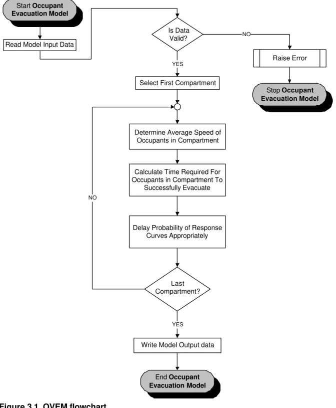
3.2 MODEL CALCULATIONS
The calculations performed by the model (Figure 3.1) are detailed in the following sections.
3.2.1. Average Speed Calculation
The weighted averaged speed of the collection of occupants in each compartment (VAVE)
∑
∑
= = = G G N 1 Group (Group) OCC N 1 Group (Group) (Group) OCC AVE N V * N V (Eq. 3-1) Where: NG = Number of groups;NOCC (Group) = Number of occupants of type Group in the compartment; and
V(Group) = Travel Speed of the occupants of type Group.
In the case where the compartment has no occupants, the above calculation will fail. In this case, the average speed of the occupants in the compartment is determined by using the fact that there are an equal number of occupants (zero) of each group type in the compartment. In such a case, the calculation becomes a straightforward average of the travel speeds of the group types. This is equivalent to replacing NOCC (Group) in the above
equation with any (non-zero) constant number.
3.3 Calculation of Time Required to Evacuate
Once the average speed of the occupants in each compartment has been established, the time required for the occupants of each compartment to successfully evacuate the building (TEVAC), measured from the moment they begin the evacuation process, becomes
simply AVE EVAC V Exit To Distance T = (Eq. 3-2)
3.4 Calculation of Probability of Successful Evacuation
The probability curves input to this model from OCRM contain the probability of occupants in each of the three compartment types beginning the evacuation process. To determine the probability of the evacuation being successfully completed, there are two steps involved for each compartment, as follows:
§ The curve corresponding to the probability of response for the current compartment’s type (FC, AC or OC), which was an input to the model, is selected. This is the
probability that the occupants in the current compartment will begin to evacuate. § This curve is shifted by the time required to complete the evacuation (TEVAC). This new
curve represents the probability that occupants of the current compartment will have successfully completed the evacuation process.
Note that the above discussion applies to both the instantaneous and cumulative probability curves input from the Occupant Response Model.
3.5 MODEL OUTPUTS
The outputs from OEVM are the probability curves (instantaneous and cumulative probabilities for each compartment) that occupants will have successfully evacuated the
building. This information is used in the Expected Number of Deaths Model to estimate how many occupants in the building would perish during the fire.
Start Occupant
Evacuation Model
Read Model Input Data
Is Data Valid? Raise Error Stop Occupant Evacuation Model End Occupant Evacuation Model
Determine Average Speed of Occupants in Compartment
Last Compartment? Select First Compartment
Write Model Output data Calculate Time Required For Occupants in Compartment To
Successfully Evacuate
Delay Probability of Response Curves Appropriately
YES
YES NO
NO
4. REFERENCES
1. Proulx, G. and Hadjisophocleous, G. 1994, Occupant Response Model: A Sub-Model For The NRCC Risk-Cost Assessment Model, The International Association for Fire Safety Science, IAFSS Conference, June 13-17, Ottawa, Canada.
2. Hadjisophocleous, G. and Yung, D., 1994, Parametric Study of the NRCC Fire RiskCost Assessment Model for Apartment and Office Buildings, Fire Safety Science -Proceedings of the Fourth International Symposium, Ottawa, Canada, pp. 829-840. 3. Proulx, G., 1994, The Time delay to Start Evacuating Upon Hearing A Fire Alarm,
38th Annual Meeting of Human Factors and Ergonomics Society, Nashville, TN, October 24-28, 1994.
4. Pauls, J.L., 1980, Building Evacuation: Research Findings and Recommendations, Fires and Human Behaviour, Edited by D. Canter, John Wiley & Sons Ltd., pp. 251-275.