Publisher’s version / Version de l'éditeur:
Vous avez des questions? Nous pouvons vous aider. Pour communiquer directement avec un auteur, consultez la première page de la revue dans laquelle son article a été publié afin de trouver ses coordonnées. Si vous n’arrivez Questions? Contact the NRC Publications Archive team at
PublicationsArchive-ArchivesPublications@nrc-cnrc.gc.ca. If you wish to email the authors directly, please see the first page of the publication for their contact information.
https://publications-cnrc.canada.ca/fra/droits
L’accès à ce site Web et l’utilisation de son contenu sont assujettis aux conditions présentées dans le site LISEZ CES CONDITIONS ATTENTIVEMENT AVANT D’UTILISER CE SITE WEB.
Proceedings of a Workshop on Recent Advances in Absorbed Dose Standards, 2003-08-21
READ THESE TERMS AND CONDITIONS CAREFULLY BEFORE USING THIS WEBSITE.
https://nrc-publications.canada.ca/eng/copyright
NRC Publications Archive Record / Notice des Archives des publications du CNRC : https://nrc-publications.canada.ca/eng/view/object/?id=c38287f6-931f-471c-a250-10468c76bef1 https://publications-cnrc.canada.ca/fra/voir/objet/?id=c38287f6-931f-471c-a250-10468c76bef1
NRC Publications Archive
Archives des publications du CNRC
This publication could be one of several versions: author’s original, accepted manuscript or the publisher’s version. / La version de cette publication peut être l’une des suivantes : la version prépublication de l’auteur, la version acceptée du manuscrit ou la version de l’éditeur.
Access and use of this website and the material on it are subject to the Terms and Conditions set forth at
Performance of an off-the-shelf clinical linac for radiation standards dosimetry
Performance of an “Off-The-Shelf” Clinical Linac for Radiation Standards Dosimetry
M. McEwen and C. Ross
National Research Council, Ottawa, Canada
Abstract
A clinical linear accelerator has been installed and commissioned at the National Research Council of Canada. Detailed testing of the linac has shown that in standard specification it can be used for reference dosimetry with a precision of better than 0.1%. Investigations focussed on geometrical precision, energy constancy, calibration of the monitor chamber, and doserate stability, and in all cases the performance exceeded the minimum required for standards-level dosimetric measurements. The ease of use, particularly in terms of selecting energy and doserate, together with this level of performance makes a clinical accelerator a viable option for the primary standards laboratory.
1. Introduction
This paper describes the experience gained in the Ionizing Radiation Standards Group at the NRC, Canada using an “off-the-shelf” Elekta clinical linear accelerator for radiation dosimetry measurements. It was felt that this information would be of interest to the standards community for a number of reasons:
i) The present generation of research linacs in use worldwide are nearing the end of their operational lifetimes and standards labs are looking for the best route to take with replacements;
ii) A number of standards labs have used older, modified clinical linacs with varying degrees of success, the assumption being that a “standard” linac will not provide the necessary levels of performance;
iii) A modern clinical linac offers the obvious advantages of ease of use and low down time as well as ensuring that the calibration and user’s beam are similar.
This paper details the installation and commissioning of the linac, including detailed investigations of the performance over the first year.
2. Installation
An Elekta Precise linac was installed at NRC in July 2002. It is a traveling wave accelerator and uses a magnetron as the microwave source. This is in contrast to the Varian and Siemens designs that use standing wave/klystron configurations. It offers three photon energies - 6, 10, & 25 MV - and five electron energies – 4, 8, 12, 18 & 22 MeV. However, the 25 MV beam is actually an 18-19 MeV electron beam with additional filtration in the X-ray target to “harden” the beam. The maximum doserate available is 5 Gy/min for photons and 8 Gy/min for electrons (although there is a High Dose Rate option to extend this latter figure by a factor of around ten). A range of PRFs (pulse repetition frequencies) are available from 400 Hz (6 MV only, 200 Hz all other energies) down to 6 Hz. The dose per pulse is in the range 0.01 – 0.04 cGy, depending on energy. Instead
of the couch that would be found in the clinical situation a rail system has been installed with a height-adjustable table. This allows measurements at a range of irradiation distances from less than 50 cm to greater than 350 cm. Full rotation of the gantry is possible although it is anticipated that the majority of measurements will be made with a horizontal beam.
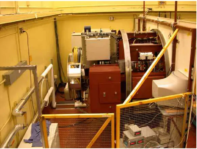
The linac is a standard machine except that there is no multi-leaf collimator (MLC) and an additional voltage stabilizer was installed to reduce any effects due to voltage fluctuations. The completed installation, which does not interfere with the operation of the older Vickers linac, is shown in Figures 1 and 2.
Figure 1. Completed installation of the Elekta Precise linac in the NRC accelerator hall.
3. Acceptance Testing
The precision required by the standards laboratory is generally better than the manufacturer’s testing specification and therefore it was not clear at the outset that the unmodified linac would meet our needs. The investigation of performance focused on four main areas – geometrical precision, energy constancy, calibration of the monitor chamber, and doserate stability. Start-up effects and beam uniformity stability were also investigated. The data presented here are generally typical of what was found for all energies, although not all measurements described have been made at all energies and modalities.
Figure 2. Rear view of the linac showing the gantry on which all major components are mounted.
4. Results and Discussion
4.1. Geometry
The ability to rotate the gantry offers a great deal of flexibility in terms of experimental setups but also introduces a possible error if the gantry moves or does not return to the same position. It was found that with the gantry positioned to give a horizontal beam there was no measurable rotational movement at the 0.05º level over several weeks and that short term repeatability was better than 0.03º. One of the design features of the Elekta is that all the major components are mounted on the gantry that rotates with the radiation head (see Figure 2). The whole system is carefully balanced so that it can be rotated by hand in case of a power failure, despite the total weight being around eight tonnes. This design also means that the turning moment of the radiation head is minimized. The other main issue was the precision of the SSD and measurements with the standard mechanical pointer gave a value of ± 0.25 mm. In addition there is a light-field SSD indicator, which is useful for setting up but is only accurate at the 1 mm level. 4.2. Energy
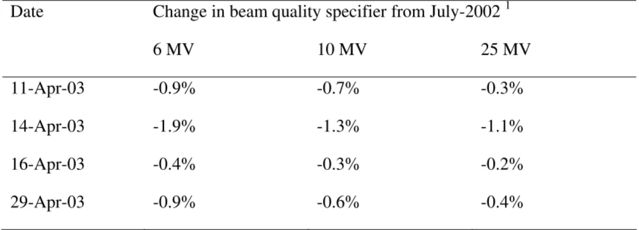
A great deal of effort has been put into characterizing the energy from the (old) NRC Vickers linac [1] and obtaining very stable electron spectra. It was thought unlikely that a clinical linac could achieve the same level of stability. Table 1 shows the results of a series of measurements of
the three photon beams, comparing the beam quality specifiers measured over a number of days with the data obtained at commissioning.
Table 1. Variation in photon energy.
Date Change in beam quality specifier from July-2002 1
6 MV 10 MV 25 MV 11-Apr-03 -0.9% -0.7% -0.3% 14-Apr-03 -1.9% -1.3% -1.1% 16-Apr-03 -0.4% -0.3% -0.2% 29-Apr-03 -0.9% -0.6% -0.4% 1
Average change for %dd10x [2] and TPR20,10 [3]
The uncertainty on each point is estimated to be 0.2% and there were similar changes in both %dd10x and TPR20,10 (%dd10x giving a generally larger change), indicating that any difference from July-02 to April-03 was not due to setup errors. As can be seen from Table 1 there is a trend with energy, which may indicate an uncorrected systematic in the system. One potential problem is that different 3-D scanning systems were used for the July-2002 and April-2003 measurements and this may be the reason for the apparent trend. However, this does not affect the day-to-day variations in beam-quality, which are at the ± 1% level – as expected, larger than for research linacs (e.g. those at NRC or NPL). For clinical measurements this level of variation is not significant as a 1% change in beam quality results in a 0.3% change in the kQ factor for an ion chamber (worst case). However, for standards measurements it is clear that some form of energy measurement is required each day. One can also see from Table 1 that the long-term drift is no greater than the day-to-day variation, although as the magnetron ages (typical life ~ 3 years) the microwave power output will drop and the electron energy will decrease.
The variations in electron beam quality were similar with day-to-day variations in R50 of around 1%. It appeared from the electron measurements that energy changes in the linac output were discrete, rather than gradual. As for the photon measurements, the dose measured is fairly insensitive to small changes in R50 – a 1% change in R50 leads to a 0.2% error in dose-to-water at the reference depth if the change is not taken into account.
Investigations using both photon and electron beams were carried out to look at energy variations during beam start-up. Energy changes will have an effect when comparing measurements over different irradiation times – e.g. a comparison of alanine and ion chamber dosimetry. For the photon measurements ionization chambers were placed at two depths - 5 cm and 10 cm – to give an instantaneous measure of beam quality (for simplicity it is referred to as “TPR” but it is more closely related to the quantity PDD10,15). Figure 3 shows the result for the 25 MV beam, for which the change is likely to be greatest (the output energy is strongly dependent on the RF power and for the 25 MV beam the linac is operating close to peak RF power).
t (s) 0 50 100 150 200 250 300 Reading (no rmalis ed to equilibr ium value) 0.98 0.99 1.00 1.01 1.02 1.03 1.04 1.05 1.06
doserate (chamber reading at 5 cm) "TPR" energy measurement
Figure 3. Variation in beam quality with beam start-up.
There is no variation in the chamber ratio (“TPR”) at the 0.2% level even though the doserate shows a 5% variation over the same timescale. In a series of measurements for all three photon energies it was found that the worst case was a 0.4% variation in “TPR” during the first 4 seconds after beam-on. This will have an insignificant effect on measurements, as irradiation times are generally greater than 15 seconds.
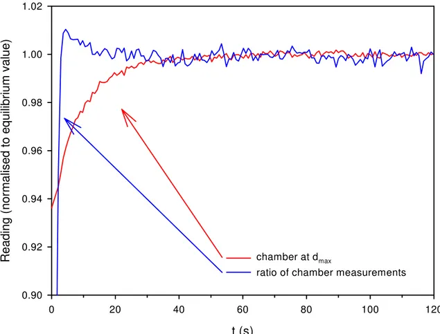
In the equivalent electron measurements, chambers were placed in a water phantom at dmax and
close to R50. A typical result for the 12 MeV beam is shown in Figure 4. As for the photon beam
it takes a significant time (> 20 s) for the doserate to stabilize.
Assuming that the variation from beam-on is entirely due to the linac output varying rather than any chamber stabilization effect then one can deduce from Figure 4 that it takes approximately 4 seconds for the energy to stabilize within 0.1 MeV of its equilibrium value. One can also compare the noise on the two signals and deduce the short-term energy stability – any energy
variation will affect the chamber measurement at R50 more than at the peak of the depth-dose
curve. Analysis of the data in Figure 4 gives a value for the energy stability (once the beam has stabilized) of ± 20 keV, which indicates that the linac control system works very well.
It was found that changes in the energy over the course of a day were generally less than 0.25% for both photon and electron beams.
t (s) 0 20 40 60 80 100 120 Read ing ( nor ma lised to eq uilib riu m valu e) 0.90 0.92 0.94 0.96 0.98 1.00 1.02 chamber at dmax
ratio of chamber measurements
Figure 4. Ion chamber response from beam-on for the 12 MeV electron beam. 4.3. Monitor chamber performance
All clinical linacs use a multi-element ion chamber to control output – doserate, stability, uniformity, etc – and any variability in the performance of the ion chamber will increase the uncertainty in dose measurements. There are three timescales of interest when looking at monitor performance – i) repeatability for a series of irradiations as might be used for determining output factors; ii) stability over the course of a day, which is important for calorimetry, where the measurements take several hours; and iii) day-to-day stability, which includes other aspects of the linac performance. For the first one, the target value for the standard deviation on a set of readings is 0.1% or less so that the monitor variability will have a negligible impact on the determination of the dose delivered. An experiment was therefore carried out where the linac was setup to deliver a series of fixed dose irradiations (100 MU) and the variation in this dose delivery was measured using an ion chamber at a depth in a water phantom. The results of such measurements for a range of linac types are shown in Table 2. The comparative data was provided by the NPL and was obtained during audit visits [4].
Table 2. Comparison of linac performance for a series of 100 MU irradiations.
Linac std dev (100 MU)
Elekta Precise 0.06% Siemens Primus 0.12% Philips SL 15 0.08% Varian 2100CD 0.04% Varian 2100EX 0.07% Varian 2300EX 0.08%
As can be seen, there are only small differences between the different linacs and chamber types. The Siemens and Varian machines use a sealed monitor whereas Elekta (and Philips) monitor chambers are vented to atmosphere. Prior to testing it was expected that that an external monitor chamber would be necessary to achieve this level of precision. However, the internal monitor chamber has performed very impressively to date. The precision on delivering a dose of 1 Gy is typically ± 0.06%, which means that an external monitor is unnecessary for measurements of this type (although an external monitor chamber may be necessary for measurements over longer timescales). An investigation using an external transmission monitor chamber mounted on the linac head (as shown in Figure 5) gave a lower standard deviation of around 0.03%.
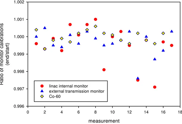
Figure 5. External transmission monitor chamber mounted on linac head using shadow tray. For longer series of measurements, such as are required for calorimetry, the drift in the monitor calibration over the period of a day is an important parameter. The monitor calibration is defined as the dose measured by a chamber in phantom for a fixed dose delivery (typically 100 MU). A
measure of the drift in monitor calibration is to take the ratio of measurements at the beginning and end of a series of irradiations, where each ratio covers a time period from 2-6 hours. Figure 6 shows typical values for the drift in monitor calibration for a series of measurements using different modalities and setups. Also shown in Figure 6 are similar results for a chamber in a Co-60 beam, where there are no beam variations to consider, and using the external monitor chamber described above. The data for the two monitor chambers were acquired for the same irradiations. The 60Co data provide a baseline against which to measure the performance of the other chambers and includes the effect of replacing the chamber at the same measurement depth, electrometer performance, etc.
Note – the x-axis is just used to label each calibration ratio – it should not be interpreted as a continuous series. measurement 0 2 4 6 8 10 12 14 16 18 R a tio of monitor calibr a tions (en d /s ta rt ) 0.996 0.997 0.998 0.999 1.000 1.001 1.002
linac internal monitor
external transmission monitor Co-60
Figure 6. Stability of monitor chambers over the course of a day.
The standard deviations for each data set are: 60Co – 0.04%, transmission monitor – 0.07%, and linac internal monitor – 0.11%. As can be seen, the linac monitor chamber generally gives repeatability better than 0.1% and there is no obvious variation with the modality or energy, which indicates very good stability in both the linac output and monitor chamber itself. The external transmission chamber gives slightly better performance, as might be expected from the short-term repeatability results. For the largest drifts seen, the degree of correlation between the two monitor values indicates that the majority of this variation is due to the changes in linac output rather than chamber response.
In comparison to the very impressive behaviour over the course of a day there are significant day-to-day variations in the monitor calibration at the ± 0.5% level. The external monitor gives
both chambers being of the unsealed type. Although all chamber measurements are temperature and pressure-corrected small volume changes – due to air pressure or applied HT – may occur for these types of thin-windowed chambers. However, these variations appear to be random and there is no apparent long-term drift over the 6 months of available data. This is in contrast to Luketina and Greig [5] who showed significant changes in monitor calibration for a Varian 2100 linac of around 2.5% per year.
4.4. Doserate
As the output from the monitor chamber is used to control the output from the accelerator it was anticipated that beam stability would be good. This is indeed the case, with an equilibrium doserate stability within a run (i.e. not taking into account start-up effects) of 0.25% for both photons and electrons, with no dependence on energy. All beams show some run-up effect, but generally the doserate is within 2% of the equilibrium value doserate within 4 seconds for photons (within 10 seconds for electrons), although equilibration at the 0.25% level can take up to 60 seconds. The example shown in Figure 3 was for the first run of the day, which is a “worst case” situation. Particularly for photon beams there can be a drift in the mean doserate over the course of a day. The largest drifts are generally seen for the 25 MV beam, where the doserate can change systematically by around 4% over a set of measurements. It is not clear what causes such drifts, but it is probably related to beam loading of the waveguide (possibly due to temperature changes), as stability for electron beams is generally much better. However, even such large drifts in doserate have little impact on the type of measurements carried out at the standards laboratory. 4.5. Beam uniformity
A typical in-phantom beam scan is shown in Figure 7.
d is ta n c e (c m ) -1 0 -8 -6 -4 -2 0 2 4 6 8 1 0 % dos e 0 2 0 4 0 6 0 8 0 1 0 0 1 2 0
For standards measurements the actual shape of the radial uniformity plot is not as important as the stability over time. As noted above there is active feedback on the linac output and therefore variations in beam uniformity are possible, in contrast to the case for the older Vickers linac where the steering/focusing settings are fixed for the series of irradiations. Although the majority of measurements are made on-axis with dosimeters of similar dimensions (e.g. ion chambers, alanine dosimeters) there is a significant difference in geometry when comparing an ion chamber with the NRC water calorimeter. The thermistor probes in the calorimeter vessel are positioned off-axis, 1 cm apart. Any variation in the beam uniformity within an irradiation or from run-to-run would have an effect on this measurement.
To investigate any time-dependence of the radial uniformity, measurements were carried out using a PMMA intercomparison phantom (Manufactured by NE Technology, now Thermoelectron Corporation) that can position two ion chambers 3 cm apart at a measurement depth of 5 cm. A series of measurements were then carried out over the course of a day to look at the variation in the ratio of the two chamber readings. The results are shown in Figure 8.
measurement 0 2 4 6 8 10 12 14 16 Cham ber ratio (norm alised to mean of set) 0.998 0.999 1.000 1.001 1.002 1.003 1.004 6 MV 10 MV
Figure 8. Variation with time of the ratio of two chambers 3 cm apart at a depth in phantom of 5 cm (measurements taken over the course of one day).
As can be seen, there are small variations in the chamber ratio at the ± 0.15% level. There is no apparent trend with time in the ratio and therefore one can conclude that the effect on the comparison of an ion chamber with the water calorimeter will be less than 0.1%.
One situation where these beam uniformity changes could have a larger effect (greater than 0.1%) is the technique of using side-by-side chambers to give the dose (as used by NPL for its photon
4.6. Start-up effects
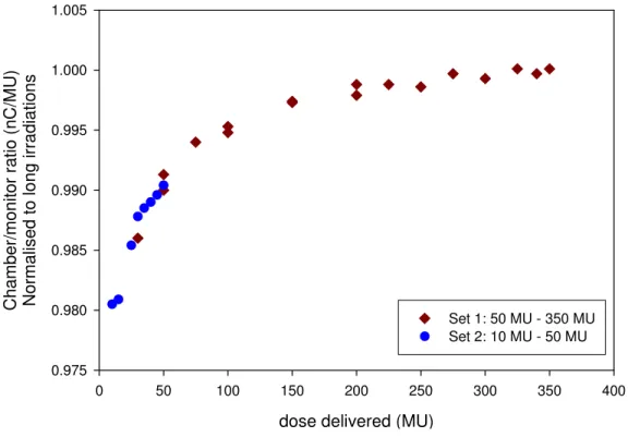
Start-up effects are particularly a concern where one is comparing dosimeters that require different irradiation times (e.g. alanine and ion chamber) and relying on the monitor chamber to accurately transfer the dose. In an investigation of this a chamber was placed at the reference depth (photon or electron beam) and a series of irradiations were carried out for a range of MU values (from 30-350). The upper limit on the MU setting was dictated by the electrometer and chamber used. An example for the 22 MeV electron beam is shown in Figure 9. The data are plotted in terms of the chamber/monitor ratio and are normalized to the longest irradiations.
dose delivered (MU)
0 50 100 150 200 250 300 350 400 Ch amb e r/ m on it o r ra ti o (n C/ MU) Normalised to lo n g ir ra dia tions 0.975 0.980 0.985 0.990 0.995 1.000 1.005 Set 1: 50 MU - 350 MU Set 2: 10 MU - 50 MU
Figure 9. Variation in chamber/monitor ratio with delivered dose (22 MeV electron beam). One would expect a straight line with value of unity, i.e. no variation in the chamber/monitor ratio with dose delivered. However, as can be seen, the variation in monitor calibration from 50 MU to 350 MU is around 1%, which is significant for primary standards dosimetry. This measurement was repeated for a range of chamber types and it was found that the behaviour was very consistent over time and independent of chamber used. Measurements down to 10 MU showed the same behaviour, and these are included in Figure 9 (accurate measurements below 10 MU were not possible due to noise and the resolution of the monitor read-out). The effect was also independent of gantry angle.
From figure 9 one can determine the error in the measured dose that would be introduced if one used the monitor calibration at 100 MU (e.g. derived using an ion chamber) for long irradiations (e.g. calorimetry, alanine, Fricke). For the 22 MeV beam one obtains a value of 0.995 – i.e. a 0.5% error. This experiment was repeated for all energies – photons and electrons and the results are shown in Figure 10. The x-axis is plotted in terms of incident electron energy, as it is most likely a linac output effect, and therefore the 25 MV is assigned a value of 18.5 MeV. The error bars are derived from repeat measurements.
electron energy (MeV) 2 4 6 8 10 12 14 16 18 20 22 24 mo nito r ca libra tion at 1 00 MU/ monito r ca libr a tion for long (50 0 MU) ir rad iatio ns 0.994 0.996 0.998 1.000 1.002 1.004 Photon beams Electron beams
Figure 10. Variation with energy of start-up effect.
As can be seen there is a general trend with energy and the agreement between photon and electron measurements indicates that it must be related to the accelerator electron beam – the energy dependence confirms that the effect cannot be due to the ion chamber/measurement system used. The uncertainty on each point is typically 0.1% and therefore it is not clear at this point whether the high point at 8 MeV is a real effect. The consistency of this difference between long and short irradiations for a given energy gives confidence that the effect can be corrected for, and therefore should not have a significant impact on dosimetry.
All the data above were taken at the maximum doserate – 500 MU/min. It was found that the effect was much reduced at lower PRFs (i.e. doserates) with no effect at the 0.05% level seen at a doserate of 125 MU/min. This further confirms that the effect is due to the linac rather than any problem with the ion chambers.
5. Initial results
Following on from these acceptance tests a number of projects have been carried out over recent months using the Elekta linac including: an investigation into the energy dependence of alanine dosimeters [7], the characterization of water equivalent materials [8] and recommissioning of the NRC water calorimeter. In each of these investigations the suitability of the linac for such standards work has been confirmed.
6. Conclusion
energy and doserate, together with this level of performance makes a clinical accelerator a viable option for the standards laboratory. However, the absolute calibration of the accelerator is only stable at the ± 0.5% level, which means for the highest accuracy measurements one must develop a suitable measurement protocol to monitor such drifts. One of the main concerns at the outset was that start-up effects would significantly affect calorimetry measurements, which use relatively short irradiations, but it would appear that these effects are very consistent, and once characterized should not have a significant impact on the dosimetry.
7. Acknowledgments
The authors would like to acknowledge the efforts of Matt Kosaki and David Marchington in ensuring that the installation of the linac and associated equipment went very smoothly. The authors would also like to thank David Niven for assisting with the measurements and Russell Thomas of the National Physical Laboratory for providing the comparison data for different linacs.
8. References
[1] McPherson, M. S. and Ross, C. K., A Magnetic Spectrometer For Electron Energy Calibration, INMS Report PIRS-0617, National Research Council of Canada, Ottawa (1998). [2] Almond, P. R. et al, TG-51 Protocol For Clinical Reference Dosimetry Of High-Energy Photon And Electron Beams, Report of AAPM Radiation Therapy Committee Task Group No. 51, Med. Phys. 26, 1847-70 (1999).
[3] International Atomic Energy Agency, Absorbed Dose Determination in External Beam Radiotherapy, IAEA Technical Reports Series No. 398, IAEA, Vienna (2000).
[4] Thomas, R., Duane, S., McEwen, M. R. and Rosser, K. E. The Role Of The National Physical Laboratory In Monitoring And Improving Dosimetry In UK Radiotherapy, Standards and Codes of Practice in Medical Radiation Dosimetry (Proc. Int. Symp. Vienna, 2002), IAEA, Vienna (2003).
[5] Luketina, I. A. and Greig, L., Linear Accelerator Output Measurements, World Congress on Medical Physics and Biomedical Engineering, Sydney (2003).
[6] Rosser, K. E., Owen, B., DuSautoy, A. R., Pritchard, D. H., Stoker, I. and Brend, C. J., The NPL Absorbed Dose To Water Calibration Service For High Energy Photon Beams, in Proc. Int. Symp. on Measurement Assurance in Dosimetry, IAEA-SM-330/35, p73, ed Flitton, S. P., IAEA, Vienna) (1994).
[7] Zeng, G., McEwen, M. R., Rogers, D. W. O. and Klassen, N. V., An Experimental And Monte Carlo Investigation Of The Energy Dependence Of Alanine/EPR Dosimetry Part I: Clinical X-Rays submitted to Phys Med. Biol. (2003).
[8] McEwen, M. R. and Niven, D., Detailed Characterization Of The Water Equivalent Material Virtual Water In High-Energy Photon And Electron Beams, World Congress on Medical Physics and Biomedical Engineering, Sydney (2003).
Discussion
Russell Thomas – When we have gone into hospitals in the UK before, we’ve upset the clinic because of the amount of time we actually want to run the beam. Have you had any troubles with overheating or ...
Malcolm McEwen – No, this is one of the things we asked at commissioning, and the engineer said it will just run and run and run. It depends on the machine, the Elekta is a travelling wave accelerator and it uses a magnetron so (you can) potentially run that a lot longer. The Siemens and the Varian are both standing wave with a klystron, the field strength’s a lot higher and you get breakdown more easily in those. (RT – Right). I know with the Siemens there have been a lot of overheating problems with the higher photon energies. We ran that for hours without any trouble, and when we were doing the commissioning the beam was on continually, doing all the scans, and there was no problem.
Michael Kramer – Do you plan to leave the gantry rotatable, or do you plan to fix it?
Malcolm McEwen – No, we plan to leave it rotatable, although we initially thought that we were going to have to install a manual brake to keep the gantry fixed in place. I had a setup where we had the head horizontal and the indicator at 3 metres, and we just used the light fields and marked it over 3 weeks. We were getting about 1 mm total movement. We checked the position each day but there was no indication of any movement, which is nice. It’s quite clever in the Elekta - they’ve put everything on the gantry and it all rotates. They balance it so you can actually move it by hand, all eight tons. This makes it easy to adjust the position but it does stay where you leave it.
David Burns – Have you looked at ion recombination or polarity effects in the monitor?
Malcolm McEwen – I’ve done no polarity or recombination measurements on the Elekta internal monitor and just some initial measurements on the external transmission monitor. One of advantages of the research linacs is the ability to change the dose per pulse very easily. With the Elekta you can’t change the dose per pulse very easily with photons due to beam loading. All the clinical machines change the dose rate by changing the prf, but with electrons you can actually change the gun current, so we can look at that. I’ve looked at leakage and that’s not a problem.
Malcolm Millar – I notice that on some of your percentage depth doses the signal seemed fairly noisy, so some of the variation you’re getting will surely depend on what peak you normalise to.
Malcolm McEwen – Absolutely, we were smoothing the data, and that was all. But then the peak was chosen from the smoothed data. But yes, we were just using a standard phantom and not doing any effort to improve it, so we were basically looking at the way you might use the system in a hospital and what variations you would get. We haven’t put any more effort into longer scans and seeing whether the variations are just due to the noise. But in electrons there was a clear shift in the data that was beyond the noise level.