HAL Id: hal-02903851
https://hal.archives-ouvertes.fr/hal-02903851
Submitted on 2 Dec 2020HAL is a multi-disciplinary open access
archive for the deposit and dissemination of sci-entific research documents, whether they are pub-lished or not. The documents may come from teaching and research institutions in France or abroad, or from public or private research centers.
L’archive ouverte pluridisciplinaire HAL, est destinée au dépôt et à la diffusion de documents scientifiques de niveau recherche, publiés ou non, émanant des établissements d’enseignement et de recherche français ou étrangers, des laboratoires publics ou privés.
Quantification of Adsorption and Optimization of
Separation of Proteins in Capillary Electrophoresis
Laurent Leclercq, Charly Renard, Michel Martin, Hervé Cottet
To cite this version:
Laurent Leclercq, Charly Renard, Michel Martin, Hervé Cottet. Quantification of Adsorption and Optimization of Separation of Proteins in Capillary Electrophoresis. Analytical Chemistry, American Chemical Society, 2020, 92 (15), pp.10743-10750. �10.1021/acs.analchem.0c02012�. �hal-02903851�
1
Quantification of adsorption and optimization of
separation of proteins in Capillary Electrophoresis
Laurent Leclercq1, Charly Renard1, Michel Martin2, Hervé Cottet1*
1
IBMM, Université de Montpellier, CNRS, ENSCM, France
2
PMMH, CNRS, ESPCI Paris – PSL, Sorbonne Université, Université de Paris, France
*Corresponding Author
HC: Tel.: +33 4 67 14 34 27; Fax: +33 4 67 63 10 46. E-mail: herve.cottet@umontpellier.fr
ABSTRACT. The improvement of separation efficiency for protein analysis in capillary electrophoresis (CE) is a challenging topic in which protein adsorption onto the capillary wall plays a crucial role. In this work, a simple method allowing to quantify the adsorption of proteins onto the coated or untreated inner surface of the fused silica capillary was developed based on the determination of the retention factor by measuring separation efficiency of individual proteins at different separation voltages (i.e. different linear velocities). This approach was applied to the quantification of the residual adsorption of four test proteins on 5-layer polyelectrolyte coatings and bare fused silica capillary. It allows to get a fair ranking of the coating performances toward protein adsorption, whatever their apparent electrophoretic mobilities (migration times) are. Due to the existence of (even low) residual adsorption, the electrophoretic operating conditions (electric field, capillary length and internal diameter) can be optimized to improve the separation performances resulting in experimental separation efficiency up to ~600 000 plates.m-1 in conditions compatible with MS coupling. This approach represents a crucial step in the course to get antifouling coatings for protein separation in CE. It can be used for the evaluation and ranking of virtually any
coating (neutral or charged) in CE.
I. Introduction
In a theoretical point of view, the separation efficiency in capillary electrophoresis (CE) is ideally controlled by axial diffusion, as expressed in equation (1) for an analyte plate number1
2 2 Vl N DL (1)
with µ the analyte apparent electrophoretic mobility, V the applied voltage, D the analyte molecular diffusion coefficient, l the effective capillary length to the detector, and L the total capillary length. For a small analyte, with D in the order of 10-9 m2s-1, equation (1) leads to N ~ 2×10⁵ plates, taking for instance V = 30 kV, l = 0.3 m, L = 0.4 m and µ = 20 TU (where TU stands for Tiselius Unit = 1×10⁻⁹ m2V-1s-1). For a protein, with D in the order of 2×10⁻¹⁰ m2s-1, equation (1) leads to N ~ 1×10⁶ plates taking the same numerical values for the other parameters. In principle, the plate number is even supposed to increase proportionally to the solute size, since the diffusion coefficient is inversely proportional to the hydrodynamic radius according to the Stokes-Einstein law2. It means that, contrary to chromatographic techniques, N should increase for larger solutes (such as proteins or other macromolecules), i.e. for solutes with lower diffusion coefficients. In practice, however, plate numbers are much lower than the maximum values predicted by equation (1), with typical plate numbers of about few thousands3, up to typically hundred thousand4 in the case of proteins.
The difference between the theoretical expectations and the experimental values is generally due to intra-capillary peak broadening, the origin of which can be found in ref 5: radial gradient temperature6 due to the combination of Joule effect and capillary cooling, capillary coiling7, electromigration dispersion also known as overloading effect8,9, and solute adsorption onto the capillary wall10-14. More recently11,12,15,16, the contribution of the electroosmotic flow (EOF) to the peak broadening in CE was also discussed as a possible source of peak broadening, especially for large solutes. The origin of the limiting factor which is controlling the separation efficiency of protein is still under debate and/or may also vary according to the experimental conditions14,17. The microheterogeneity of the proteins themselves (e.g. due to deamidation of asparagin or glutamin amino acid residues) is also sometimes cited as a potential source of peak broadening since poorly separated multiple variants or conformers of a given protein can lead to the occurrence of peak broadening or peak shoulders14. When occurring, the solute adsorption onto the capillary surface is known to strongly decrease the separation efficiency18. This is especially true in the case of protein separation. That is why many different coatings approaches have been studied and developed in the past, to optimize the separation efficiency and repeatability for protein analysis19-26. Polyelectrolyte multilayers (known as SMIL, for Successive Multi-Ionic Layers) have been introduced in CE by Katayama et al. in 199827, and consisted in the superposition of
3
alternating oppositely charged polyelectrolyte layers on the capillary surface. The coating protocol is generally simply based on a succession of capillary rinsing, and the number of layers can be easily varied to control the direction of the EOF. Two or four layer SMIL coatings28 are generally used in neutral or basic conditions for the separation of acidic (negatively charged) proteins, while three or five layer coatings26 are suited for the separation of basic proteins in acidic conditions. Several parameters were investigated to optimize the separation efficiency for peptide or protein analysis using SMIL coatings, such as: the number of polyelectrolyte layers26,29,30, the polyelectrolyte layer thickness31-33 controlled by the ionic strength of the electrolyte used for building the SMIL30,34, the ionic strength of the BGE35, the polyelectrolyte concentration and molar mass36,37, the rinsing protocol36, and the coating stabilization/conservation29,34,38. More recently, it was shown that the nature of the couple of polyelectrolytes used to build the SMIL coating had a great impact on the separation efficiency and repeatability4,26. Surprisingly, even the nature of the polyelectrolyte which is not on the last layer of the SMIL coating was found crucial26. Morphology, roughness and thickness of SMIL layers have also been observed by atomic force microscopy (AFM)39, including imaging of charge distribution by using a modified cantilever with tip-tethered avidin, resulting in adhesion maps with nanometer resolution28,40.
Despite, all these experimental efforts, a general and simple method able to quantify the protein adsorption onto the capillary surface, and allowing to rank the coating performances is still lacking18,41. This work aims at developing such a simple experimental method based on the theory of electrochromatography, for the evaluation and the ranking of coating performances in terms of protein/solute adsorption. We propose in this work to take the retention factor (as defined in chromatography) as a good estimator of the residual protein adsorption onto the capillary surface. Since the retention factors in CE are expected to be small, it is difficult to measure them based on the migration times (and as it would be done for chromatographic techniques). That is why we propose to determine the residual retention factor based on the separation efficiency. This concept was applied on a protein test mixture using 5-layer SMIL coated capillaries in a volatile BGE electrolyte compatible with MS coupling. Using this approach, polybrene (PB) – poly(methacrylic acid) (PMA) SMIL performances were estimated and compared with PB – poly(L-lysine citramide) (PLC) SMIL coating and with bare fused silica capillary. In a second part of this work, the influences of experimental parameters such as the electric field, the capillary length, the capillary diameter on the separation performances, and more specifically on the separation efficiency, are
4
discussed with some rules of thumb to find the optimal conditions for each of these parameters.
II. Materials and methods
II.1. Chemicals
Polybrene (hexadimethrine bromide, PB, Mw 15 000 g.mol-1, pKa = 10.5) was purchased from
from Sigma-Aldrich (Saint-Quentin Fallavier, France). Poly(methacrylic acid) (PMA, Mw 50
000 g mol-1, Polydispersity index (PDI) = 2.5, pKa = 4.2-4.8) was synthesized as previously
described42. Poly(L-Lysine citramide) (PLC, Mw 20 000 g.mol-1) is a carboxylic polyacid
composed of building blocks based on alternating L-lysine and citric acid moieties, kindly supplied by M. Boustta (IBMM, Université de Montpellier, France). 4-(2-hydroxyethyl)-1-piperazine ethanesulfonic acid (HEPES) and acetic acid glacial were purchased from VWR (Fontenay-sous-bois, France) and sodium hydroxide was from Sigma-Aldrich (St Quentin Fallavier, France). Trypsin Inhibitor (TI, from soybean, purity not indicated by the supplier), Myoglobin (Myo, from equine skeletal muscle, purity ≥ 95%), Ribonuclease A (RNase from bovine pancreas, purity ≥ 60%) and Lysozyme (Lys, from chicken egg white, purity ≥ 90%) were from Sigma-Aldrich (St. Louis, USA). Ultrapure water (18.2 MΩ.cm) was obtained using a MilliQ system from Millipore (Merck, Molsheim, France).
II.2. SMIL coatings
5-layer SMIL coatings were prepared by successive flushes of the capillary with the polyelectrolyte solutions. Polyelectrolyte solutions (cation: PB; anion: PMA or PLC) were prepared at 3 g.L-1 in the 20 mM HEPES / 10 mM NaOH, pH 7.4 buffer. The experimental coating protocol is given in SI with all the details about the applied pressure for all the flushes depending on the capillary internal diameter (see Table SI1).
II.3. Capillary electrophoresis
Capillary electrophoresis experiments were carried out on a P/ACE™ MDQ Beckman-Coulter (Sciex, Villebon sur Yvette, France) piloted by 32 Karat software. Bare fused silica capillaries are purchased from Composite Metal Services (Photon Lines, France). Different dimensions of capillary were used, as mentioned in Table SI1, with the effective length being 10 cm less than the total capillary length.
5
Electrophoretic separations were performed in a 0.5 M acid acetic BGE at pH 2.5 (3.13 mM ionic strength). Separation voltage was set between 10 kV and 30 kV (see Figure caption). Before each run, the capillary was flushed for 3 min at the flushing pressure indicated in Table 1. Protein mixture was injected into the capillary at different pressures according to the capillary dimensions (see Table 1). The protein mix was made of TI, Myo, RNase, Lys at 0.2 g L-1 each in pure water. 0.1% m/v DMF was used in co-injection as electroosmotic flow marker. Separations were realized at different applied voltages as indicated on the Figures showing the electropherograms. The temperature of the capillary cartridge was set at 25°C. UV detection was performed at 214 nm.
The separation efficiency was estimated by the plate number using the following equation:
2 5.54 t N (2)
where t is the migration time at the peak apex and δ is the half-height peak width determined using CEval 0.6h3 software (based on the full peak) available at the following address [https://echmet.natur.cuni.cz/software/ceval]. In further calculations, the plate height H was obtained from equation 3:
l H
N
(3)
The linear migration velocity u of a given protein was experimentally obtained via equation 4: l
u t
(4)
III. Theoretical part
III.1. Influence of adsorption on separation efficiency in CE
Adsorption onto the capillary wall in CE is similar to considering open tubular electrochromatography (OT-CEC), where the solute may adsorb onto the coating of the capillary. In this situation, if we assume that axial molecular diffusion and adsorption are the main causes of peak broadening, equation (5) - which is similar to the Golay equation - can be used to express the plate height (H) as a function of the analyte retention factor k on the stationary phase14,43:
6 2 2 2 2 2 2 2 16(1 ) 3 (1 ) f m c m m s d u d u D k k H u D k D k (5)
where D is the molecular diffusion coefficient (m²s-1) of the analyte in the background electrolyte, dc is the internal diameter of the capillary, df isthe coating film thickness, Ds is the
molecular diffusion coefficient in the stationary phase located on the capillary surface. In this equation, um is the velocity of the analyte when it is moving in the liquid phase, owing to its
electrophoretic mobility and to the electroosmotic mobility. In chromatography, it corresponds to the mobile phase velocity. But, in CE, this velocity um is different for each
protein and is related to the experimentally accessible (apparent) migration velocity, u, as:
1
m
u
u
k
(6)If we assume that the
2 3
f s
d
D term is negligible compared to the 2
32
c d k
Dterm in the right side of
equation (5), since the film thickness (df, approx. 10-20 nm39) is much smaller compared to
the internal diameter of the capillary (dc, typically 50 µm), equation (5), combined to eqs. (4)
and (6), reduces to:
2 2 2 2 1 2 1 32 1 c u k d Hl Dt k D k (7)This latter expression (7) represents the ratio of the actual variance of the peak to that it would have in absence of adsorption for the same migration time. It sets the dependence of the peak broadening contribution due to the adsorption according to the experimental parameters (retention factor k, linear migration velocity u, internal capillary diameter dc, and molecular
diffusion D).
III.2. Determining the retention factor by varying the separation voltage
From equation (7), it is possible to calculate the retention factor k by plotting
2
Hl
Dt as a function of
u
2for a given analyte, where u is experimentally varied by changing the separation voltage. H and u are calculated from the electropherograms obtained at different applied voltages (see Section II.3). Such a plot is a straight line with a y-intercept equal to 1/(1+k) and a slope p given by:7 2 2 2 32 (1 ) c k d p D k (8)
Resolving equation (8) in k leads to the following equation and to the related solution (only the solution with a physical meaning is retained):
2 2 2 1 0 32 c d k k pD (9) 1 1 4 2 A k A with 2 2 32 c d A pD (10)
III.3. Influence of the capillary length and the capillary I.D. on the
theoretical plate number
At constant electrical field, u is constant, and the plate number per capillary length N/l, equal to 1/H, is given from equation (7) by:
2 1 2 1 N u l D pu k (11)
For a given protein (i.e. at constant p), N
l is independent of l, hence N is proportional to l. As in gas chromatography, the retention factor, k, in OT-CEC is linked to the equilibrium distribution constant K of the analyte between the background electrolyte and the coating via:
4 f S m c d V k K K V d (12)
where Vs and Vm are the volumes of stationary and mobile phases and df is the thickness of the
film of stationary phase. At constant df, k decreases when dc increases. This means that the
larger the capillary I.D. is, the lower the retention is. Since um is assumed to be independent of dc (while u increases with increasing dc, due to lower retention), it is convenient to express N/l
as a function of um, K, dc, df and D by replacing u by um/(1+k) in equation (11), and k by
4 f
c Kd
8 2 2 2 2 2 1 2 1 4 2 1 m f m f c u N K d u l D Kd D d (13)
From equation (13), it appears that, for a given thickness df of the coating, N
l is supposed to increase when dc decreases. This can be counter-intuitive, since the retention factor k is
increasing with lower dc. However, the mass transfer is faster for smaller capillary I.D.,
explaining the higher separation efficiency.
At this point, it should be noted, that, although the protein interactions with the capillary wall are classically considered as an adsorption effect, the expression of the stationary phase mass transfer contribution to the plate height use in equation (5) - last term of this equation - is that corresponding to a partition process. However, whatever the mechanism causing protein retention, in both cases, the retention factor is inversely proportional to the capillary diameter so that the conclusion derived above about the variation of N/l with dc for a partition
mechanism also applies for an adsorption one. By the way, partitioning mechanism is more likely to occur on a SMIL coating, while adsorption would be expected on bare fused silica.
III.4. Optimum velocity in CE with adsorption
Because, as reflected by Eq. (5), two processes (axial diffusion and transversal mass transfer) varying in opposite ways with the analyte migration velocity contribute to band broadening, there exists, as in chromatography, an optimum velocity, um,opt, at which the plate height
reaches a minimum value, Hmin, corresponding to a maximum plate number, Nmax. The
expressions of these quantities are obtained by deriving Eq. (5) with respect to um, and,
neglecting the stationary phase mass transfer contribution (last term of this equation), are given by
, 1 8 2 m opt c k D u k d (14)
2 2 1 min c k H d k (15)9
min 2 1 1 max c k N l H k d (16)and the optimum migration time, topt, is
8 2 c opt ld k t D (17)
IV. Results and discussion
IV.1. Determination of protein retention factor on SMIL coatings and
influence of the applied voltage
In this work, we propose to take the experimental retention factor as a quantitative estimation of the protein adsorption onto the coating of the capillary wall. To obtain the experimental retention factors of test proteins (Trypsin Inhibitor, Myoglobin, RNase and Lysozyme) onto a SMIL coated capillary, electrophoretic separations were performed at different voltages from 10 to 30 kV in 0.5 M acetic acid. The main characteristics of the studied proteins are presented in Table SI2. A five layer PB-PMA SMIL coating was selected for this study, since it was previously reported as a performant SMIL coating in acidic conditions4. Figure 1 displays the electropherograms of the protein separation at different applied voltages. Excellent repeatability was obtained, as observed by the superposition of the five repetitions for each separation voltage.
10
Figure 1. Superposition of five repetitions of electropherograms of the protein test mixture obtained at different applied voltages as indicated on the graph on a 5-layer PB-PMA SMIL coated capillary. Experimental conditions: 5-layer PB-PMA SMIL coated capillary, 40 cm total length (30 cm to the detector) 50 µm I.D. Background electrolyte: 0.5 M acetic acid, pH 2.5.Flush before each run: BGE 14.5 psi, 3 min. Hydrodynamic injection: 0.4 psi, 4 s for protein mixture. Co-injection of 0.1% DMF in ultrapure water: 0.4 psi, 4 s. Sample mixture and peak identification: TI (1), Myoglobin (2), RNase (3), Lys (4) at 0.2 g L-1 each in water. Temperature: 25°C. For the coating procedure: see the experimental section II.2.
From these electropherograms, the dimensionless
2
Hl
Dt term, which also represents the ratio of the dispersion coefficient to the molecular diffusion coefficient, was determined experimentally for each protein and each separation voltage. As expected,
2
Hl
Dt was found to vary linearly according to u² (see Figure 2 and equation (7)). This means that the dispersion coefficient on a SMIL coated capillary increases quadratically with the linear velocity u (and therefore with the applied voltage), due to the analyte adsorption on the capillary surface. This is very different from what is expected for CE when the peak broadening is only controlled by axial diffusion. In that latter case, the dispersion coefficient is independent of u, and equal to the diffusion coefficient as far as the Joule heating is not too important8. The determination of the retention factors of the test proteins on the SMIL coating is obtained from the slope
2 2 2 32 (1 ) c k d p D k
of each line observed in Figure 2 (see equation (7)). The slope p is an
increasing function of k. Knowing D (determined by Taylor dispersion analysis elsewhere26, see numerical values in Table SI2) and 2
c
d , k can be determined using equation (10) by solving a second order equation in k for each protein (see equation (9)). The numerical values of k are gathered in Table 1 (PB-PMA, 50 µm I.D.). The retention factor on the PB-PMA SMIL coating varies between 0.025 (Myo) and 0.046 (TI). Chromatographically speaking, these retention factors are very low; but it is interesting to notice that such a weak retention leads to significant peak broadening with
2
Hl
Dt values which can reach up to 45 at high voltage/velocity (see e.g. TI for u2~3.8×10⁻⁶ m2 s-2, 30 kV, in Figure 2 ). The determination of the retention factor is a practical way to quantify the interaction between a given protein and the SMIL coating (or any other type of coating). In the present case, TI and Lys are the most adsorbed proteins on the PB-PMA coating, followed by RNase and Myo.
11
Figure 2. Representation of
2 Hl
Dt
as a function of u² for 4 proteins on a 5 layers PB-PMA SMIL coating and 50 µm I.D. capillary. u2 is varied by changing the separation voltage (see Figure 1). Experimental conditions as in Figure 1. Error bars are ± one SD on n=5 repetitions. TI (■ y = 11.1 u2
+ 2.12; R² = 0.998), Myo (♦ y = 11.1 u2 + 1.60; R² = 0.999), RNase (▲ y = 6.7 u2 + 2.95; R² = 0.995), Lys (● y = 6.7 u2 + 1.52; R² = 0.997) where u2 is in 10-6 m²s-2.
Figure 3. Representation of N
l (left axis) or N (right axis) as a function of the separation voltage V on a 5-layer PB-PMA SMIL coating. Experimental conditions as in Figure 1. Error bars are ± one SD on n=5 repetitions. TI (■ N/l = 268106 V-0.81 ; R² = 0.98), Myo (♦ N/l = 272106 V -0.74 ; R² = 0.98), RNase (▲ N/l = 1.33106 V -0.22 ; R² = 0.93), and Lys (● N/l = 3.18106 V -0.30 ; R² = 0.97) where V is in V and N/l in m-1. Experimental conditions as in Figure 1.
Practically, the impact of the weak adsorption of the proteins on the peak broadening can be minimized by lowering the voltage, since in practice the apparent solute velocities are always higher that the optimal values given by eq. (14). This can be verified by plotting in double logarithmic scales N/l (or simply N) as a function of the separation voltage V (see Figure 3, left and right y-axis). Figure 3 clearly displays a decrease of the plate number with increasing
0 10 20 30 40 50 60 0 1 2 3 4 Hl /2 Dt u² (10-6m²/s²) TI Myo RNase Lys
12
voltage. Again this is a marked contrast with CE where N/l increases with increasing V. As
N/l scales as ~
(1 ²)
u pu
for low k (see equation (11)) and u is proportional to V, the higher the retention factor, the higher the p value, and the higher the dependence of the plate number with the voltage. This explains why TI and Myo, which have the highest slopes p, have the highest values of α in the N/l vs V plots presented in Figure 3, where is defined as N/l ~ V-α.
α values are reported in Table 1.
IV.2. Influence of the capillary internal diameter and capillary length
A similar series of experiments were performed on capillaries of different diameters using 5-layer PB-PMA SMIL coatings as presented in SI (see Figure SI1 and SI2 for 25 µm I.D. and see Figures SI3 and SI4 for 75 µm I.D.). For the capillaries of different diameters, the range of applied voltage was adapted to avoid Joule effect (see Figure SI5 for the determination of the voltage range on each capillary), and the injection pressure was chosen to ensure similar injected plug lengths for all capillary I.D.. The protocol of SMIL preparation was also adapted to have the same flushing velocity and rinsing (or contact) time for each polyelectrolyte layer during their construction for all the capillaries of different I.D. (see SI for the experimental details) to ensure similar coating properties (thickness, density). From Table 1, it appears that
k decreases when the capillary I.D. increases, which is in good agreement with the theory (see
equation (12)). Figure 4 shows the variation of k according to the capillary I.D. in double logarithmic scale. The mean slope (obtained by averaging the slope of each protein) is ~ -0.83 in good agreement with the expected dc-1 dependency (see equation (12)).
Regarding the peak broadening, the
2
Hl
Dt term decreases with decreasing dcas expected from equation (7), and as verified experimentally by comparing for instance Figure 2 with Figure SI2. In terms of separation efficiency, N
l is increasing when dc decreases. This can be counter-intuitive, since the retention factor k is increasing with lower dc. However, the mass
transfer in liquid phase is faster for smaller capillary I.D., explaining the higher separation efficiency.
As for the influence of the capillary length, the presence of residual adsorption should not affect the linearity of the plate number with the capillary effective length (at constant velocity, i.e. constant voltage). This was verified experimentally (see section 5 in SI, and Figures SI6
13
and SI7). This linear dependence also holds in chromatography and in CE in absence of adsorption (as stated by equation (1)).
Figure 4. Representation of k dependence on the capillary I.D. for 5-layer PB-PMA SMIL coated capillaries. Experimental conditions as in Figures 1, SI1 and SI3. TI (■ k = 0.49 dc-0.64,
R² = 0.933), Myo (♦ k = 1.36 dc-1.04, R² = 0.985), RNase (▲ k = 0.94 dc-0.84), and Lys (● k =
0.82 dc-0.79, R² = 0.96), where dc is in µm.
0.01
0.1
10
100
k
d
c(µm)
TI
Myo
RNase
Lys
14
Table 1. k, p and α parameters determined on 5-layer SMIL coatings and bare fused silica with capillaries of different I.D. Experimental conditions: as in Figure 1 for PB-PMA SMIL coating on a 50 µm I.D. capillary; as in Figure SI1 for PB-PMA SMIL coating on a 25 µm I.D. capillary; as in Figure SI3 for PB-PMA SMIL coating on a 75 µm I.D. capillary; as in Figure SI8 for PB-PLC SMIL coating on a 50 µm I.D. capillary, and as in Figure SI10 for Fused Silica on a 50 µm I.D. capillary. See SI for the coating protocol.
PB-PMA PB-PLC Fused Silica
25 µm 50 µm 75 µm 50 µm 50 µm pa k (10-2) pa k (10-2) αb pa k (10-2) pa k (10-2) pa k (10-2) TI 4.9 ±0.5 6.2 ±1.2 11.1 ±0.3 4.6 ±0.6 0.81 ±0.07 10.7 ±0.1 3.0 ±0.4 7.6 ±0.2 3.8 ±0.5 203±13 21.3 ±3.2 Myo 9.2 ±0.5 4.6 ±0.8 11.1 ±0.1 2.5 ±0.3 0.75 ±0.05 8.3 ±1 1.4 ±0.2 10.8 ±0.7 2.5 ±0.4 192±9 10.9 ±1.6 RNase 5.2 ±0.2 6.4 ±1.0 6.7 ±0.5 3.6 ±0.6 0.22 ±0.04 n.d. n.d. 5.9 ±0.5 3.3 ±0.5 128±4 16.6 ±2.3 Lys 3.7 ±0.1 6.3 ±1.0 6.7 ±0.5 4.2 ±0.6 0.30 ±0.03 5.8 ±0.8 2.6 ±0.5 6.8 ±0.4 4.2 ±0.6 51±2 12.0 ±1.7 a
: in 106 s²m-² ± one standard deviation on the slope
b
15
IV.3. Comparison and ranking of different SMIL coatings and fused silica
capillary
The determination of the retention factor via the influence of the separation voltage on the peak broadening, as discussed for Figure 2, is a very convenient way to quantitatively estimate the residual adsorption of the proteins onto the capillary surface, and therefore, to rank the different capillary coatings in their effectiveness to reduce protein adsorption. Numerical k values obtained for 5-layer PB-PMA and 5-layer PB-PLC coatings on 50 µm I.D. capillaries were compared and are gathered in Table 1. The different separations obtained for PB-PLC coating at different voltages are displayed in Figure SI8 with the
2
Hl Dt vs u
2
plot allowing to determine the k values (see Figure SI9). It appears that the k values are, on the whole, slightly lower or similar on the PB-PLC coating (0.038±0.005 for TI; 0.025±0.004 for Myo; 0.033±0.003 for RNase and 0.042±0.006 for Lys) compared to the PB-PMA coating (0.046±0.006 for TI; 0.025±0.003 for Myo; 0.036±0.006 for RNase and 0.042±0.006 for Lys). To demonstrate the interest of SMIL coating to reduce the adsorption onto the capillary surface, k values were also determined on a 50 µm I.D. fused silica capillary (see Table 1 and Figure SI10 and SI11). In addition to a much lower migration time repeatability on fused silica capillary compared to SMIL coatings, retention factors k were about 3-5 times higher on fused silica capillary compared to SMIL coatings (0.213±0.001 for TI; 0.109±0.003 for Myo, 0.166±0.003 for RNase and 0.12±0.02 for Lys).
IV.5. Optimization of the separation efficiency
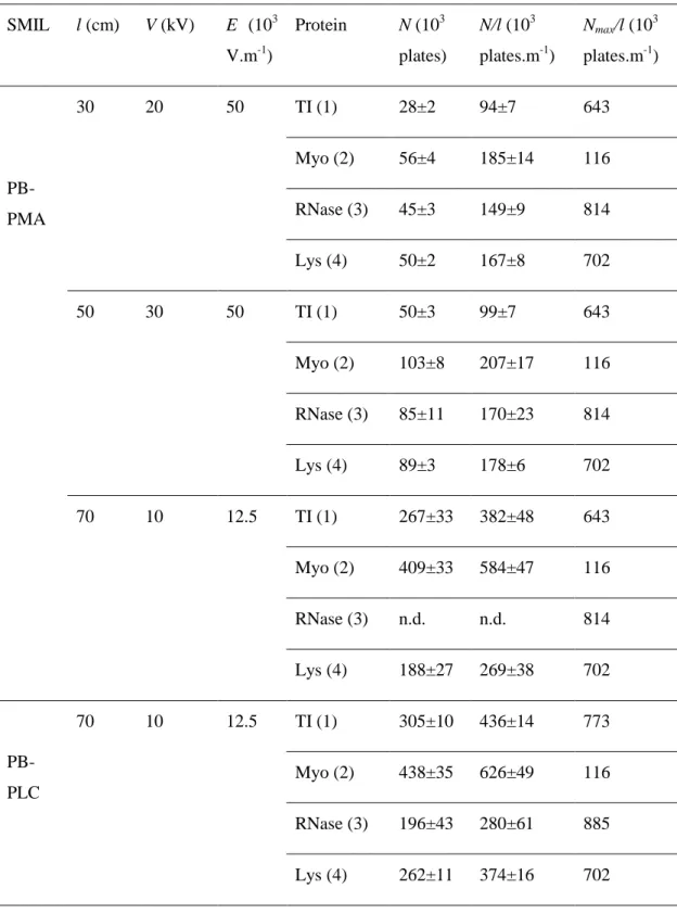
In this section, we consider the improvement of the separation efficiency by simultaneously adjusting the experimental parameters (voltage, capillary length, capillary I.D.) on SMIL coatings. As an example of optimization, N and N/l values obtained for a 5-layer PB-PMA coating on a 50 µm I.D. for different capillary lengths and voltages are presented in Table 2. The corresponding electropherograms are presented in Figure SI12. At a constant electric field of 50×103 V m-1, N increases with increasing effective length by a factor of about 2 corresponding to the effective length ratio (50/30~1.7, see Table 2), while the N/l values remain almost unchanged (as expected). Reducing the electric field from 50×103 V m-1 to 12.5×10³ V m-1 and increasing the effective capillary length to 70 cm leads to average plate numbers N~230×103 plates (N/l~330×103 plates m-1). Even better results could be obtained on
16
the most efficient PB-PLC SMIL coating in similar operating conditions with average plate numbers N ~300×103 plates (N/l~429×103 plates.m-1).
As discussed in the theoretical section, there is an optimum in velocity, hence in voltage, that maximizes the separation efficiency (see eqs (15) to (17)). The weaker is the adsorption phenomenon, the larger are the optimum velocity and the maximum plate number and the smaller is the optimum migration time. Indeed, for a pure electrophoretic process, since dispersion solely arises from axial diffusion, the shorter the time spent by the analyte in the capillary, the smaller the band broadening. However, the course for achieving very high efficiencies in CE by applying very high voltages becomes limited by increasing relative instrumental (injection and detection) contributions to band broadening as well as adverse Joule heating effect and dispersion by electromigration. From equations (16) and (17), and the
D and k values of the four model proteins reported in Tables SI2 and Table 1, for a 50 µm I.D.
capillary with the PB-PMA SMIL coating, it can be calculated that the maximum plate numbers per meter are equal to 640,000, 1150,000, 819,000, 704,000, for TI, Myo, RNase and Lys, respectively. It is noticeable that the maximum plate number does not depend on the diffusion coefficient of the analyte but solely on its retention factor and on the capillary diameter. However, the optimum migration velocity, and thus, the optimum applied voltage and the optimum migration time, depends on the diffusion coefficient of the analyte, as seen in equations (14) and (17).
The fact that the plate numbers reported in Figure 3 decrease with increasing voltage for each analyte, indicates that, in agreement with Eq. (14), the experimental migration velocities of the proteins were larger than the optimal ones, so that the liquid phase mass transfer is dominating the dispersion process. They are approaching these optimal values at the lowest voltage (10 kV).
17
Table 2. Separation efficiencies obtained on 5-layer PB-PMA and PB-PLC SMIL coatings with
different optimized conditions. Experimental conditions: Capillary dimensions, 40/60/80 cm (30/50/70 cm to detector) × 50 µm I.D.. Electrolyte: 0.5 M acetic acid, pH 2.5. Applied voltages and electric fields as indicated in the Table. Sample mixture: TI (1), Myo (2), RNase (3) and Lys (4) at 0.2 g L-1 each in water. Injection parameters: 0.4 psi, 4 s for l = 30 cm; 0.4 psi, 6 s for l = 50 cm; 0.4 psi, 8 s for
l = 70 cm. Temperature: 25°C. See SI for the coating procedure.
SMIL l (cm) V (kV) E (103 V.m-1) Protein N (103 plates) N/l (103 plates.m-1) Nmax/l (10 3 plates.m-1) PB-PMA 30 20 50 TI (1) 28±2 94±7 643 Myo (2) 56±4 185±14 116 RNase (3) 45±3 149±9 814 Lys (4) 50±2 167±8 702 50 30 50 TI (1) 50±3 99±7 643 Myo (2) 103±8 207±17 116 RNase (3) 85±11 170±23 814 Lys (4) 89±3 178±6 702 70 10 12.5 TI (1) 267±33 382±48 643 Myo (2) 409±33 584±47 116 RNase (3) n.d. n.d. 814 Lys (4) 188±27 269±38 702 PB-PLC 70 10 12.5 TI (1) 305±10 436±14 773 Myo (2) 438±35 626±49 116 RNase (3) 196±43 280±61 885 Lys (4) 262±11 374±16 702
18
V. Conclusion
The essential advantage of CE over other separation methods, such as chromatography, lies in its ability to provide very high separation efficiencies. This arises from the fact that, whatever their radial position in the capillary tube, except in a the very narrow region near the capillary wall, analyte molecules all move at the same velocity under the applied electrical field, so that the dispersion of the zones solely arises from axial molecular diffusion. For this reason, electro-osmosis was employed as a flow driving process in packed column or open-tubular electrochromatography44. Its plug-like or quasi-plug-like flow profile indeed allows high efficiencies for unretained or little retained compounds45. However, it was found that, although the efficiency of electro-driven systems are better than that of pressure-driven ones, their relative advantage decreases significantly with increasing retention46-48. A similar situation is encountered, as shown in this study, in capillary electrophoresis with adsorption, even for a rather weak one, since, as shown in Figure 2, the dispersion coefficient can be over 40 times larger than it would be in absence of interactions with the capillary wall.
In this work, a simple method allowing to quantify the adsorption of proteins onto the capillary surface was developed based on the determination of the retention factor using the theory of band broadening in open-tubular electrochromatography. The retention factor can be easily determined by measuring the separation efficiency of the individual proteins at different separation voltages (i.e. different linear velocity). Interestingly, we have proposed in this work to determine the residual retention factor based on the separation efficiency instead of using retention (migration) times as it would done in chromatography. This approach is justified by the fact that the mass transfer correcting term in the plate height due to weak adsorption in CE and electrochromatography is essentially proportional to the square of the retention factor, while this term does depend only little on k for a pressure-driven system. From equations presented in section III, it can derived that the relative rate of change of the efficiency (measured by the plate height, the plate number, or still the temporal or spatial variance), per unit change of k, (dH/H)/dk, is 2/k times larger than the relative rate of change of the migration time per unit change of k, (dt/t)/dk, in the low k range, for the high voltages used in CE. Hence, with k values around 0.04 found for the various proteins with the SMIL coatings, the sensitivity of the determination of the retention factor from plate height changes is about 50 times larger than that obtained from migration time changes.
19
This approach allows to quantitatively rank the separation performances of the different capillary coatings. PB-PLC coatings lead to slightly better performances than PB-PMA coating, and significant decrease of the retention factor compared to fused silica. Even if the values of k were very small on SMIL coatings (typically between 0.01 and 0.1), these are the signature of a residual protein adsorption limiting the plate numbers that are experimentally accessible.
Actually, the existence of very weak residual adsorption onto the capillary surface makes the electrophoretic separation world shifting into the chromatographic world. As a consequence, operating CE conditions should be optimized to improve the separation efficiency, with rules of thumb which are counter-intuitive for CE users. The electric field should be kept close to an optimum value, providing the maximum plate number achievable for a protein, with acceptable compromise with the analysis time, which is a very different conclusion compared to what is expected for CE in absence of adsorption. Longer capillary also brings higher plate numbers N, with N being proportional to the effective capillary length. Finally, and counter-intuitively but supported by the theory on OT-CEC, lower internal diameter also increases the separation efficiency due to lower mass transfer resistance. Performing a separation on a long capillary, and low electric field results in level of separation efficiency up to ~600 000 plates.m-1 in conditions compatible with MS coupling.
Finally, we believe that the present approach should greatly help to find the best suited capillary coating for a given application by quantifying the residual adsorption. We can also anticipate that the million theoretical plates should be routinely accessible by combining the best low adsorption coating with the best experimental operating conditions.
Supporting Information. Experimental protocol of the SMIL coatings. Main characteristics of the studied proteins. Electropherograms and Hl/(2Dt) vs u2 plots for PB-PMA (25 µm and
75 µm I.D.); Ohm laws; Study of different capillary lengths on a 50 µm I.D. PB-PMA SMIL coated capillary; Study on PB-PLC SMIL capillary coating and bare fused silica capillary; Electropherograms of optimized separations; A and p values for SMIL coated and fused silica capillaries
20
References
(1) Jorgenson, J.W.; Lukacs, K.D., Anal. Chem. 1981, 53, 1298-1302.
(2) Lindken, R.; Rossi, M.; Grosse, S.; Westerweel, J. Lab Chip. 2009, 9, 2551–2567. (3) Pattky, M.; Huhn, C. Anal. Bioanal. Chem. 2013, 405, 225–237.
(4) Leclercq, L.; Morvan, M.; Koch, J.; Neusüß, C.; Cottet, H. Anal. Chim. Acta. 2019,
1057, 152–161.
(5) Gaš, B.; Kenndler, E. Electrophoresis 2000, 21, 3888–3897. (6) Xuan, X.; Li, D. Electrophoresis 2005, 26, 166–175.
(7) Kasicka, V.; Prusik, Z.; Gas, B.; Stedry, M., Electrophoresis 1995, 16, 2034-2038. (8) Beckers, J.L. J. Chromatogr. A 1994, 662, 153–166.
(9) Malá, Z.; Gebauer, P.; Boček, P. Anal. Chim. Acta 2016, 935, 249–257.
(10) Khaledi, M.G. (Ed.) High Performance Capillary Electrophoresis – Theory, Techniques, and Applications, Wiley Intersci. (2007).
(11) Ghosal, S. Electrophoresis 2004, 25, 214–228.
(12) Ghosal, S. Annu. Rev. Fluid Mech. 2005, 38, 309–338.
(13) Gaš, B.; Štědrý, M.; Kenndler, E. Electrophoresis 1997, 18, 2123–2133. (14) Schure, M.R.; Lenhoff, A.M. Anal. Chem. 1993, 65, 3024–3037.
(15) Khodabandehloo, A.; Chen, D.D.Y. Anal. Chem. 2017, 89, 7823–7827. (16) Griffiths, S.K.; Nilson, R.H. Anal. Chem. 2000, 72, 4767–4777.
(17) Engelhardt, B.H.; Beck, W.; Kohr, J.; Schmitt, T. Angewandte Chemie, Int. Ed. 1993,
32, 629-649.
(18) Castelletti, L.; Verzola, B.; Gelfi, C.; Stoyanov, A.; Righetti, P.G. J. Chromatogr. A 2000, 894, 281–289.
(19) Hajba, L.; Guttman, A., Trends Anal. Chem. 2017, 90, 38-44. (20) Dolník, V. Electrophoresis 2008, 29, 143–156.
(21) Righetti, P.G.; Gelfi, C.; Verzola, B.; Castelletti, L. Electrophoresis 2001, 22, 603– 611.
(22) Lucy, C.A.; MacDonald, A.M.; Gulcev, M.D. J. Chromatogr. A 2008, 1184, 81–105. (23) Dawod, M.; Arvin, N.E.; Kennedy, R.T., Analyst 2017, 142, 1847-1866.
(24) Stepanova, S.; Kasicka, V., Anal. Chim. Acta 2016, 933, 23-42.
(25) Renard, C.; Leclercq, L.; Stocco, A.; Cottet, H. J. Chromatogr. A 2019, 1603, 361–370. (26) Bekri, S.; Leclercq, L.; Cottet, H. J. Chromatogr. A 2015, 1399, 80–87.
(27) Katayama, H.; Ishihama, Y.; Asakawa, N. Anal. Chem. 1998, 70, 2254–2260.
(28) Stock, L.G.; Leitner, M.; Traxler, L.; Bonazza, K.; Leclercq, L.; Cottet, H.; Friedbacher, G., Ebner, A.; Stutz, H. Anal. Chim. Acta 2017, 951, 1–15.
21
1888–1898.
(30) Graul, T.W.; Schlenoff, J.B. Anal. Chem. 1999, 71, 4007–4013. (31) Dubas, S.T.; Schlenoff, J.B. Macromolecules 1999, 32, 8153–8160.
(32) Clark, S.L.; Montague, M.F.; Hammond, P.T. Macromolecules 1997, 30, 7237–7244. (33) Dubas, S.T.; Schlenoff, J.B. Macromolecules 2001, 34, 3736–3740.
(34) Nehmé, R.; Perrin, C.; Cottet, H.; Blanchin, M.D.; Fabre, H. Electrophoresis 2008, 29, 3013–3023.
(35) Catai, J.R.; Tervahauta, H.A.; De Jong, G.J.; Somsen, G.W. J. Chromatogr. A 2005,
1083, 185–192.
(36) Schlenoff, J.B.; Dubas, S.T.; Farhat, T. Langmuir 2000, 16, 9968–9969.
(37) Ödberg, L.; Sandberg, S.; Welin-Klintström, S.; Arwin, H. Langmuir 1995, 11, 2621– 2625.
(38) Fritz, J.S.; Steiner, S.A. J. Chromatogr. A 2001, 934, 87–93.
(39) Haselberg, R.; Flesch, F.M.; Boerke, A.; Somsen, G.W. Anal. Chim. Acta 2013, 779, 90–95.
(40) Leitner, M.; Stock, L.G.; Traxler, L.; Leclercq, L.; Bonazza, K.; Friedbacher, G.; Cottet, H.; Stutz, H.; Ebner, A. Anal. Chim. Acta 2016, 930, 39–48.
(41) Verzola, B.; Gelfi, C.; Righetti, P.G. J. Chromatogr. A 2000, 868, 85–99.
(42) Leclercq, L.; Pollet, A.; Morcellet, M.; Martel, B. Eur. Polym. J. 1999, 35, 185–193. (43) Golay, M.J.E., Theory of chromatography in open and coated tubular columns with
round and rectangular cross-sections. In "Gas Chromatography 1958", Desty, D. H. Ed., Butterworths, London, 1958, pp. 36-68.
(44) Pretorius, V.; Hopkins, B.J.; Schieke, J.D. J. Chromatogr. 1974, 99, 23-30. (45) Tsuda, T.; Nomura, K.; Nakagawa, G. J. Chromatogr. 1982, 248, 241-247. (46) Giddings, J.C. J. Chromatogr. 1961, 5, 46-60.
(47) Martin, M.; Guiochon, G. Anal. Chem. 1984, 56, 614-620.
(48) Martin, M.; Guiochon, G.; Walbroehl, Y.; Jorgenson, J.W. Anal. Chem. 1985, 57, 559-561.
22


![[PDF] Apprendre C++ avec QtCreator Collectionner les pointeurs | Formation informatique](data:image/gif;base64,R0lGODlhAQABAIAAAP///wAAACH5BAEAAAAALAAAAAABAAEAAAICRAEAOw==)