HAL Id: hal-01114285
https://hal-univ-paris.archives-ouvertes.fr/hal-01114285
Preprint submitted on 9 Feb 2015
HAL is a multi-disciplinary open access
archive for the deposit and dissemination of
sci-entific research documents, whether they are
pub-lished or not. The documents may come from
teaching and research institutions in France or
abroad, or from public or private research centers.
L’archive ouverte pluridisciplinaire HAL, est
destinée au dépôt et à la diffusion de documents
scientifiques de niveau recherche, publiés ou non,
émanant des établissements d’enseignement et de
recherche français ou étrangers, des laboratoires
publics ou privés.
User-space Multipath UDP in Mosh
Matthieu Boutier, Juliusz Chroboczek
To cite this version:
User-space Multipath UDP in Mosh
Matthieu Boutier
[email protected]
Juliusz Chroboczek
[email protected]
Sorbonne Paris Cité, PPS, UMR 7126, CNRS, F-75205 Paris, France
Abstract
In many network topologies, hosts have multiple IP ad-dresses, and may choose among multiple network paths by selecting the source and destination addresses of the packets that they send. This can happen with multihomed hosts (hosts connected to multiple networks), or in mul-tihomed networks using source-specific routing [2]. A number of efforts have been made to dynamically choose between multiple addresses in order to improve the relia-bility or the performance of network applications, at the network layer, as in Shim6 [5], or at the transport layer, as in MPTCP [9]. In this paper, we describe our ex-perience of implementing dynamic address selection at the application layer within the Mosh Mobile Shell [12]. While our work is specific to Mosh, we hope that it is generic enough to serve as a basis for designing UDP-based multipath applications or even more general APIs.
1
Introduction
Standard networking APIs are mainly designed with the implicit assumption that a client with a single address connects to a server with a single address. This assump-tion is often incorrect: many hosts have multiple ad-dresses, either because they are multihomed (connected to multiple networks) or connected to a network that is itself multihomed.
WiFi 3G
Figure 1: A multihomed host
Multihomed hosts Many hosts have are connected to multiple networks (Figure 1). The most common case is that of a mobile host connected to the Internet over multi-ple network technologies (e.g. WiFi and cellular or WiFi
and Ethernet), but this is also the case of servers with redundant connectivity. Since hosts do not typically par-ticipate in the routing protocol, multihomed hosts have multiple addresses, one per network interface.
A similar situation arises with double-stack hosts, that have both IPv4 and IPv6 addresses. While both ad-dresses are assigned to the same network interface, such hosts are multihomed from the point of view of the higher layers.
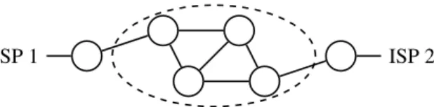
ISP 1 ISP 2
Figure 2: A network connected to two providers Source-specific routing and multihomed networks Similar to a multihomed host, a multihomed network (Figure 2) is one that is connected to the Internet over multiple physical links, either for fault tolerance or in or-der to improve throughput or reduce cost. Classically, such networks are assigned Provider-Independent (PI) addresses that are announced over all links, in which case the dynamic nature of the routing protocol automatically provided for fault-tolerance; improvements in through-put and reductions in cost can be achieved by careful en-gineering of the routing protocol.
PI addresses need to be announced in the Internet’s global “Default-Free Zone” and cannot be easily aggre-gated; they are therefore a costly resource. For smaller networks, it is a natural proposition to announce multi-ple Provider-Dependent prefixes, one to each provider. In this case, the internal routing protocol must be able to perform source-specific routing (sometimes called SADR), where outgoing packets are routed to the right gateway depending on their source. We describe our ex-perience with source-specific routing elsewhere [2].
1.1
Choosing addresses dynamically
In the presence of multiple addresses, hosts must choose a pair of a source and a destination address for every packet that they send. The usual approach is to make this choice at connection establishment: the set of pos-sible (source, destination) pairs is ordered according to a set of static rules [4], and the first that works is used throughout the lifetime of the connection. This is some-times slightly refined by probing all of the possible pairs in parallel [11].
An obvious drawback of such a relatively static ap-proach is that the choice of addresses cannot be changed once a connection has been established, with the conse-quence that a network hiccup will cause all established connections to drop (or, worse, to hang). A number of researchers have come up with protocols that switch ad-dresses mid-connection; this can be done at the network layer, at the transport layer, or, as in our work, at the ap-plication layer.
Network layer Shim6 [5, 8] is a host-centric layer 3 shim which provides reliability in multihomed networks. When a connection is established by higher layers to a remote host, Shim6 exchanges the local and remote ad-dresses. If the connection is broken, Shim6 finds an alter-native working path and changes the source and destina-tion addresses of both the outgoing and incoming packets of the connection. This operation is totally transparent to the higher layers.
Shim6 detects failures based on the natural traffic of the application: if packets are sent without response, then it is likely that a failure has occurred. In that case, Shim6 finds another responsive path using the reachability pro-tocol (REAP) [1].
REAP builds a list of all possible paths, and probes them to find one that works. REAP probes can be fairly heavyweight, since they contain information about the other probes sent and received, allowing REAP to detect and benefit from unidirectional paths. To limit the over-head of probes, REAP sorts the flows with a number of heuristics before probing them with an exponential back-off interval between two probes. Naderi et al. [6] remark that having more aggressive probing is desirable in prac-tice, since it achieves fastest convergence while the over-head will likely be less than the broken connection’s traf-fic.
Transport layer Multiple source and destination ad-dresses can be chosen by the transport protocol, as is the case in Multipath TCP (MPTCP) [9] and SCTP [10].
MPTCP is a reliable flow-oriented TCP-compatible protocol which establishes as many alternative paths as possible. These paths are called subflows, and provide
both reliability and better performance: MPTCP is able to balance traffic between its subflows, without perfor-mance losses due to slow flows. Subflows are continu-ously estimated by regular TCP messages, which act as probes.
SCTP is a reliable, message-oriented, connection-oriented protocol, designed to achieve reliability in mul-tihomed networks. When a SCTP connection (associa-tion) is established, a primary path is selected by each end-point and used to send packets to the other one. A number of mechanisms allow the end-points to exchange their addresses and build alternate paths. These paths are regularly probed at at fixed intervals (heartbeats) to check their reliability. When a failure is detected on the primary path, one of the working alternate paths is se-lected to be the new primary path. The protocol defini-tion gives no guidelines about the strategy to be used to switch to a better path when the primary path is active but less efficient than other paths.
Application layer A server’s addresses are usually stored within the DNS, and the client will try them all, either in turn [4] or in parallel [11]. Once a flow is estab-lished, it is no longer possible to change the source and destination addresses — from the user’s point of view, all connections are broken whenever a link outage forces a change of address.
A TCP connection is bound to a pair of addresses at connection establishment; however, a number of modern applications are based upon UDP and implement their own scheduling and retransmission strategies. This is notably the case of VoIP applications (SIP, Skype, etc.), of some recent peer-to-peer file transfer applications [7], and of Mosh, the Mobile Shell, an SSH replacement de-signed for lossy and high-latency links [12].
Since standard Mosh doesn’t implement full multi-path, it is unable to survive certain classes of topology changes. In the rest of this paper, we describe our imple-mentation of multipath for Mosh, and our experiences with our implementation.
2
The original Mobile Shell
The Mobile Shell is a lightweight and responsive remote shell. It differs from SSH mainly by two aspects. On the one hand, it predicts what should display the terminal while waiting for a server confirmation, which increase the user experience on slow links, and on the other hand, it uses the UDP transport protocol with an algorithm lim-iting the impact of packet loss and reordering.
Mosh is composed of multiple layers: the front-end layer, the transport layer and the network layer. The front-end layer is in charge of interaction with the user,
1 bit 63 bits direction sequence number ) 64 bits nonce 16 bits timestamp
16 bits timestamp reply
Figure 3: Original Mosh packet format
client-side, and with the remote host, server-side. It in-cludes the prediction algorithm, and communicates with the server through the Mosh transport layer.
The transport layer is in charge of keeping the states of the two peers in sync and of data fragmentation. It is also its responsibility to deal with packet loss and re-ordering: essentially, it maintains the knowledge of the last acknowledged state, and tries to send deltas from that state to the current local state. If a packet is lost, its con-tent will (probably) be included in the next packet, avoid-ing the need for a retransmission. Reorderavoid-ing is also not a problem: as newer packets have also the information bring by the older, the older has just to be ignored.
The network layer is in charge to receive and send packets, estimate the Maximum Transmission Unit (MTU), Round Trip Time (RTT) and Retransmission TimeOut (RTO), encrypt and decrypt packets, and keep connection active, even in the presence of NAT. Our modifications to enable multipath are confined to the net-work layer.
Mosh network protocol The Mosh network protocol
header is described in Figure 3, and consists of 12 octets (96 bits) The first 64 bits contain a cryptographic nonce, a flag indicating the direction of the flow (client to server, or server to client), and the message sequence number (seqno). The rest of the header consists of two timestamp fields used to measure the RTT.
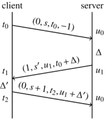
RTT measurement When a packet is about to be sent, the timestamp field is filled with the host’s current times-tamp, and the timestamp reply field is set to the last timestamp received from the remote peer plus the time elapsed since the packet bringing that timestamp was re-ceived. The RTT is computed as the difference of the current timestamp and the timestamp reply field of each packet; and is averaged by an exponential mean to com-pute the smoothed RTT (SRTT).
Figure 4 illustrates this process: the client sends a packet destined to the server (destination= 0), with se-qno s, timestamp t0, and timestamp reply −1, because it
has not yet received a timestamp from the server. The server receives the packet at time u0, and stores both t0
and u0 as the last timestamps received from the client.
When it next sends data to the client, at time u1, it fills the
packet with the right destination field (destination= 1),
client server t0 u0 (0, s,t 0,−1) ∆ u1 t1 (1, s 0,u 1,t0+ ∆) ∆0 t2 u0 (0, s +1,t 2,u1+ ∆0)
Figure 4: A Mosh network layer exchange
its seqno s0, the timestamp u1, and the timestamp reply
t00= t0+ ∆ = t0+ (u1− u0). On reception, the client
com-putes the value of the RTT as RTT= t1− t00, and stores
the two timestamps for future messages.
In order to keep accurate measurements, only in-order messages are considered, i.e. messages with a strictly in-creasing sequence number. The payload of out-of-order packets is still transmitted to the transport layer, but the control information is ignored.
Connection timeout As Mosh uses UDP, an unreliable transport protocol, it must determine when the connec-tion has been lost. Mosh uses the standard RTO compu-tation, as defined in TCP: RTO= SRTT + 4 × SRTTVAR. The timeout value is not used by the network layer, but by the higher layers, so that data are sent at regular in-tervals to continuously monitor the connection, and to inform the user that the connection has been lost.
Connection loss A connection can be lost due to many causes: network failure, link removal, changing IP ad-dresses, or NAT timeouts. Mosh makes a best effort to keep the connection active, and will never give up with-out an explicit request from the user.
If the connection times out, data packets are still sent to the server, but at larger intervals. When the network offers connectivity again, the connection recovers almost immediately.
Mosh resists to IP address changes because by using the sendto system call with no explicit source address, leaving the responsibility of choosing the source address to the operating system. It is therefore possible to use the same Mosh session from multiple addresses (e.g. after moving a laptop).
NATs sometimes time out active connections. As
NATs associate a connection to the 5-tuple (transport protocol, IP src, IP dst, port src, port dst), a Mosh client switches ports regularly when it has no sign of the server. This is done by creating and using a new socket to send
data. Mosh retains a small number of older sockets, in case a packet from the server arrives for a previously used port.
Limitations of Mosh In some cases, the mechanisms implemented in Mosh are not sufficient to keep a con-nection, or simply to choose the best connection among multiple possible ones. In a multi-address environment, a Mosh client may have multiple paths to reach the des-tination; since Mosh lets the system choose the source address, it will not switch to a better path or change pro-tocol familites.
3
Multipath Mosh
There are potentially as many different paths as pairs (s, d) of addresses, where s is a client address and d a server address. Our implementation of a multipath Mosh continually estimates the latency of each of these paths and selects the best one. We call flow the structure repre-senting a path and its characteristics; this corresponds to MPTCP’s subflows or SCTP’s paths.
We have added a flag field to the network layer proto-col in order to have more types of messages. We use it to differentiate data, probes, and address gathering. Proto-col details are described in Section 4.
3.1
Address gathering
In order to build all possible flows, the client must gather both its local addresses and the server’s addresses. Both the client and the server have access to their local ad-dresses through standard APIs (such as getifaddrs) provided by the system. At bootstrap, the client has a reachable address of the server: in combination with its local addresses, it builds an initial set of flows.
Gathering server’s addresses The client asks the
server for its addresses at regular intervals. In particular, it sends an address request at bootstrap to quickly have a complete set of flows. Both the request and the reply messages are tagged with the ADDR_FLAG flag bit.
On reception of a message with the ADDR_FLAG set, the server answers with the set of its local addresses. The message bringing the answer is also tagged with the ADDR_FLAG, and may not contain other data than the server’s addresses.
On reception of a message with the ADDR_FLAG set, the client parses the message and extracts the server’s local addresses. It then completes the set of flows it has to the server. Existing flows are not modified.
Address pair filtering Some pairs of addresses will not lead to a valid flow: for example, an IPv4 source address cannot be used with an IPv6 destination address. Filtering such incompatible combinations can reduce the number of flows being probed. Of course, determining if combination is valid or not is not always obvious, and it is more desirable to consider too many flows rather than filter out good ones.
We only do very limited filtering in our implementa-tion, such as verifying that the two addresses of the same pair have the same address family, are both loopback ad-dresses or not, and are both link-local or not. While more discrimination would be possible, we prefer to keep a more general implementation, the overhead being toler-able (see Section 3.5).
3.2
Sending packets on a flow
To send a datagram on a given flow, we must specify both its source and destination IP addresses. There are three possible implementations:
• using one socket per flow, each bound both to a local address (with bind) and to a remote address (with connect). Sending and receiving messages on a particular flow is then done with the send and recv system calls: the socket parameters indicate without ambiguity which are the local and remote addresses of both outgoing and incoming packets.
• using one socket per local address, in combination with the sendto and recvfrom system calls, which respectively set the destination of outgoing packets, and retrieve the remote peer address of incoming packets. The local address is specified and retrieved as previously, by the socket.
• using one socket per network-layer protocol (IPv4, IPv6), with the sendmsg and recvmsg system calls which allow to specify and retrieve both the source and the destination address of each packet.
After a number of experiments, we have decided to use the third one: it results in a much simpler implemen-tation, especially in the presence of port hopping (see above).
More precisely, messages are sent with the sendmsg system call, with the msg_name and msg_namelen fields providing the destination address. The source address is provided by a control message (msg_control and msg_controllen). In IPv4, we use IP_PKTINFO and IP_SENDSRCADDR, depending on the operating system; IPv6 provides the portable API IPV6_PKTINFO. (We have found out that this only works if the socket is ex-plictly bound to the wildcard address — on some sys-tems, using an unbound socket leads to a kernel panic.)
We did consider using a single hybrid (IPv6 and IPv4) socket. Unfortunately, hybrid sockets’ options are a small subset of plain IPv6 options, not sufficient for our needs.
3.3
Flow selection
Mosh is an interactive lightweight protocol: the metric we want to optimize is clearly the RTT, and load balanc-ing is not in our scope. To measure the RTT, very small messages, called probes, are regularly sent on flows to estimate their latency. Probe exchanges are only initiated by the client: the server only response to probes.
We consider that paths are bidirectional and symmet-ric, so the client and the server use the same flow at any one given time. This flow is selected by the client, which chooses the flow with lowest RTT, while the server merely selects the flow of the latest in-order data packet received to send data back.
We didn’t implement any mechanism to limit insta-bility, which is not a problem in the case of Mosh. In-deed, having instability with two paths of roughly same RTT will at worst cause packet reordering, which is not a problem for the higher layers of Mosh. Our tests with flows of similar RTT exhibited good behaviour, but more investigation in this area may be needed.
3.4
Probing flows
Probing flows consists in periodically sending small mes-sages, known as probes, that carry enough information to estimate the flow’s RTT. The interval between two probes is determined dynamically: waiting for a flow RTT up-date should be of the same order of magnitude as the RTT itself; in effect, faster paths will be probed more often than slower ones. Beyond a certain frequency, however, sending more probes no longer improves the user expe-rience. For that reason, our implementation never sends more than one probe every 500 ms.
An additional issue is that of non-functional flows: since no probes will be received, the RTT will not be nat-urally increased, while a single packet loss should not be considered as a broken path. We maintain an idle_time field in the flow structure which represents the time dur-ing which a flow has not been responsive. The SRTT value of an idle flow is unchanged, but the value used for choosing flows is the sum of the SRTT and the idle time. A packet loss, or lack of response, is detected using RTO. We use the standard TCP’s RTO computation, also taking the idle time into account:
RTO:= (SRTT + idle_time) + 4 × SRTTVAR
When a RTO has elapsed with no response from the server, the client immediately sends another probe, even if the next probe for this flow was delayed, and the idle time is increased by one RTO. Increasing by no more than one RTO is important, even if more time elapsed since the last probe sending: the event loop may give us back control after a lot of time, leading to a signifi-cant over-estimation of idle time on a simple packet loss. We observed delays of several seconds, leading the mosh client to choose a worst flow. On the other hand, increas-ing by one RTO is enough: since the computation of the RTO takes the idle time into account, it is the same be-haviour on idle flows as doubling the RTT each time:
idle_time := idle_time + RTO
Mosh uses delayed acknowledgements. To compen-sate, the Mosh network layer receives the maximum lay interval from the higher layers, and computes a de-layed RTO (dRTO). The dRTO is used to compute the probing interval and the actual timeout of packet ac-knowledgements, but we keep the RTO value to increase the idle time: the delays induced by the delayed acknowl-edgements are not representative of the real idle time. This leads to the following equations:
dRTO:= RTO + max_delack probe_interval := max(dRTO,500ms)
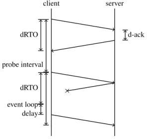
An example of the whole process is described in fig-ure 5: the client sends a probe to the server, and sched-ules the next probe. The server receives the probe, and delays the acknowledgement before sending back a probe. The client receives the acknowledgement in dRTO, so it waits for the end of the probe interval to send again a probe to the server. This time, the server de-cides to send back the probe immediately, but the packet is lost. The client notices the loss when the event loop next yields control: it adds RTO to the flow’s idle time, and immediately sends back a probe, without waiting for a whole probe interval.
3.5
Probe overhead
Our approach will lead to permanent overhead in the net-work, with regular probes on each flow. As the number of flows is the product of the number of local addresses and the number of remote addresses, it might in principle grow to fairly large values.
Figure 6 shows the overhead induced by one flow, de-pending on the probe interval. These values are real-world measurements (obtained using wireshark). One probe is contained in an Ethernet frame of less than 90 octets. An idle flow, having a probe interval higher than
client server dRTO d-ack probe interval × dRTO event loop delay
Figure 5: Probe scheduling
Probe interval (ms) 100 500 1000 10000
IPv6 overhead (B/s) 900 180 90 9
IPv4 overhead (B/s) 720 144 72 7.2
Figure 6: Ethernet probing frame overhead of one flow.
10 seconds, will lead to an overhead of less than 10 B/s, while an active and efficient flow will lead to an overhead of less than 200 B/s.
Considering a client and a server having 4 (compat-ible) addresses each, 16 flows will be built. If each of these flows has latency better than 500 ms, we will have an overhead of less that 3 kB/s for the whole network.
4
Protocol details
In this section, we describe the modifications made to the Mosh network protocol. The new packet header is rep-resented in Figure 7. There are two main modifications: the identification of flows by a flow ID, and the presence of a flags field.
Flow ID In standard mosh, the cryptographic nonce is constituted of the direction and the sequence number. The direction indicates if the message was sent by the client (with a value of 0), or by the server (value of 1), while the sequence number is used by the received to de-termine whether the packet is the most recent one. As the nonce has double usage, and needs to be unique, mosh gives up when the sequence number overflows (wraps around to 0). Since it is a 63-bit value, this is unlikely to be a serious problem.
We use a separate flow ID, allocated by the client, to identify flows, and sequence numbers increase indepen-dently for each flow. Both the flow ID and sequence
1 bit 15 bits 48 bits direction flow ID sequence number 64 bits nonce 16 bits flags 16 bits timestamp
16 bits timestamp reply
Figure 7: Multipath Mosh packet format
length family port address
1 1 2 length - 3
Figure 8: Address sub-messages format
number are encoded in the nonce, and the server and the client must retain flow IDs. The client reuses exist-ing flow IDs when new pairs of addresses become pos-sible: both the client and the server will have a limited amount of flow’s structure in memory, equal to the max-imum number of simultaneous flows encountered during the session.
Flags The Flags field is used to extend the network layer protocol. Two flags are defined: the PROBE_FLAG and the ADDR_FLAG. Currently, the flags serve as a mes-sage type: either none or exactly one of the two flags will be set, identifying the type of message.
Because the main objective of a probe is to be lightweight, a probe does not carry any extra data from higher layers, and therefore is exactly 14 bytes long.
An address request message, i.e. a message with ADDR_FLAG set and originated by the client, doesn’t carry any extra-information, like a probe. An address response message contains the list of the server’s addresses, in the format described in figure 8: 1 octet for the sub-message length (in octets), 1 octet for the address family, 2 octets for the port number, and the rest for the address (4 octets for IPv4 addresses, and 16 octets for IPv6 addresses).
Since an address request is always sent at the begin-ning of the connection, it may in principle be possible for a malicious program to send duplicates of a message containing an address request; since the server’s reply is much larger than the request, this could be used for an amplification attack. For that reason, we ignore address request packets unless they are in-order.
5
Results
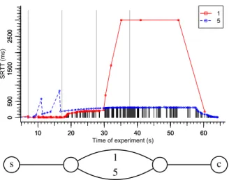
We tested our implementation in a simple testbed illus-trated in figure 9: the client and the server are connected to two routers connected by two distinct paths. We use the Linux netem module to simulate variable delay and loss ratios on our links, and unplug an Ethernet cable to
0 0 500 1500 2500 0 500 1500 2500 SR T T (ms) 10 20 30 40 50 60 10 20 30 40 50 60 1 5 Time of experiment (s) s 1 c 5
Figure 9: Testing mp-mosh on delayed or broken paths
simulate a connection loss with no address changes. The routing is assured by the Babel routing protocol [3].
In this graph, we only use two flows, and we bound the higher plots to 3 seconds, both for readability purposes. Each of the black segments at the bottom of the graph represents a sent packet, and indicates which flow has been chosen to send the data. The two curves indicate the RTT values computed by Mosh.
Initially, both paths have negligible delay. At time 7 s, we add 300 ms delay on (the path taken by) flow 5: Mosh’s estimate converges slowly to that value while data are sent on flow 1. This paths happened to experi-ment two isolated packet losses, which increased the idle time, but didn’t disturb the SRTT value computation.
At time 17 s, we add 200 ms on flow 1: its SRTT com-putation grows quickly to the expected value, and data continue taking this flow, which still has the lower la-tency. The convergence of the RTT is faster, since flow 1 received a larger number of packets. Only a small num-ber of probes were sent on flow 5.
At time 28 s, we unplug the Ethernet cable used by flow 1. The first data packets are sent on flow 5 roughly one second later, and the RTT of flow 1 grows without bound (bounded at 3 s on the figure).
Finally, at time 38 s, we plug back the Ethernet ca-ble. This time, Mosh takes around 21 seconds to recover, which is the time needed for the lower layers (notably routing) to recover, and to the probing interval which has already reached its maximum value (10 s in our imple-mentation).
6
Limitations and future work
Mosh doesn’t consume much bandwidth. Contrary to MPTCP, we didn’t need to balance the load on
multi-ple flows, but only choose the most responsive. As the Mosh-transport layer is resilient to packet’s reordering, it would be possible to split traffic among multiple flows; we have not investigated this possibility.
Our implementation makes no efforts to avoid insta-bility when multiple flows have similar latency; this did not appear to be a problem in our experiments. In high-throughput scenarios, Mosh may fragment messages into multiple UDP datagrams; in that case, Mosh only buffers a single message; if two different fragmented messages overlap, both might be discarded. Further experimenta-tion is necessary in order to determine if this is a problem in practice, and whether it is more desirable to increase the amount of buffering done by Mosh, or to limit the amount of instability, which might in turn decrease our algorithm’s responsivity to link outages (and perhaps the amount of natural load balancing due to instability.)
Mosh is an application designed to have a mobile client and a fixed server. Client and server thus have strongly asymmetric roles. We have used this property, putting all the intelligence on the client side with no choice of the path on the server side. In other appli-cations, both the client and the server might be mobile, which would require smarter server-side algorithms.
Our implementation assumes that the links are sym-metric, both in reachability and in delay. Asymmetric protocols such as REAP require larger probes, since each probe needs to carry information about the other flows. It is not clear to us whether this is worthwile in real-world topologies, and whether the overhead can be somehow reduced.
7
Conclusion
We have designed and implemented a multipath version of mosh, using the assumption that using different source and destination addresses leads to different paths. We use active and continuous probing to estimate the RTT of the flows induced by these paths, while having techniques to (i) limit and adapt the number of probes depending on the performances of the flows, (ii) quickly discriminate idle flows while not being affected by occasional packet loss, and (iii) deal with external time delays to allow delayed acknowledgements and event loop integration.
Our implementation achieves fast re-convergence, small overhead, and does not interrupt the event-loop to generate extra traffic. Our modifications are contained in the Mosh network layer, built as a separate C++ library: it could in principle be used by any UDP-based applica-tion that would benefit from multiple paths.
8
Available software
Our multipath mosh implementation is available at: http://github.com/boutier/mosh
References
[1] Arkko, J., and van Beijnum, I. Failure Detection and Locator Pair Exploration Protocol for IPv6 Multihoming. RFC 5534 (Pro-posed Standard), June 2009.
[2] Boutier, M., and Chroboczek, J. Source-specific routing. sub-mitted for publication(2014).
[3] Chroboczek, J. The Babel Routing Protocol. RFC 6126 (Experi-mental), Apr. 2011.
[4] Draves, R. Default Address Selection for Internet Protocol ver-sion 6 (IPv6). RFC 3484 (Proposed Standard), Feb. 2003. Obso-leted by RFC 6724.
[5] Garc´ia-Mart´inez, A., Bagnulo, M., and Van Beijnum, I. The shim6 architecture for ipv6 multihoming. Communications Mag-azine, IEEE 48, 9 (2010), 152–157.
[6] Naderi, H., and Carpenter, B. Experience with ipv6 path probing. Internet-Draft draft-naderi-ipv6-probing-00, IETF Secretariat, October 2014. http://www.ietf.org/ internet-drafts/draft-naderi-ipv6-probing-00.txt. [7] Arvid Norberg. uTorrent transport protocol. BEP-29, October
2012. http://bittorrent.org/beps/bep_0029.html. [8] Nordmark, E., and Bagnulo, M. Shim6: Level 3 Multihoming
Shim Protocol for IPv6. RFC 5533 (Proposed Standard), June 2009.
[9] Raiciu, C., Paasch, C., Barr´e, S., Ford, A., Honda, M., Duch-ene, F., Bonaventure, O., and Handley, M. How hard can it be? designing and implementing a deployable multipath tcp. In USENIX Symposium of Networked Systems Design and Imple-mentation (NSDI’12), San Jose (CA)(2012).
[10] Stewart, R. Stream Control Transmission Protocol. RFC 4960 (Proposed Standard), Sept. 2007. Updated by RFCs 6096, 6335. [11] Wing, D., and Yourtchenko, A. Happy Eyeballs: Success with
Dual-Stack Hosts. RFC 6555 (Proposed Standard), Apr. 2012. [12] Winstein, K., and Balakrishnan, H. Mosh: An interactive remote
shell for mobile clients. In USENIX Annual Technical Conference (2012), pp. 177–182.