Publisher’s version / Version de l'éditeur:
Engineering Journal, 57, 5-6, pp. 73-80, 1974-05
READ THESE TERMS AND CONDITIONS CAREFULLY BEFORE USING THIS WEBSITE.
https://nrc-publications.canada.ca/eng/copyright
Vous avez des questions? Nous pouvons vous aider. Pour communiquer directement avec un auteur, consultez la première page de la revue dans laquelle son article a été publié afin de trouver ses coordonnées. Si vous n’arrivez pas à les repérer, communiquez avec nous à PublicationsArchive-ArchivesPublications@nrc-cnrc.gc.ca.
Questions? Contact the NRC Publications Archive team at
PublicationsArchive-ArchivesPublications@nrc-cnrc.gc.ca. If you wish to email the authors directly, please see the first page of the publication for their contact information.
NRC Publications Archive
Archives des publications du CNRC
This publication could be one of several versions: author’s original, accepted manuscript or the publisher’s version. / La version de cette publication peut être l’une des suivantes : la version prépublication de l’auteur, la version acceptée du manuscrit ou la version de l’éditeur.
Access and use of this website and the material on it are subject to the Terms and Conditions set forth at
Empirical method for calculating fire resistance of protected steel
columns
Lie, T. T.; Stanzak, W. W.
https://publications-cnrc.canada.ca/fra/droits
L’accès à ce site Web et l’utilisation de son contenu sont assujettis aux conditions présentées dans le site LISEZ CES CONDITIONS ATTENTIVEMENT AVANT D’UTILISER CE SITE WEB.
NRC Publications Record / Notice d'Archives des publications de CNRC:
https://nrc-publications.canada.ca/eng/view/object/?id=a5dd1e8a-ee3b-4220-8dc5-5f2adc8ce740 https://publications-cnrc.canada.ca/fra/voir/objet/?id=a5dd1e8a-ee3b-4220-8dc5-5f2adc8ce740Empirical Method for
Calculating Fire Resistance
of Protected Steel Columns
by
T.T. Lie and W.W. Stanzak
Reprinted from Enqineerinq Journal
9_ Vol. 57, No. 5 / 6 , ~ a ; / ~ u n e 1974, p. 73
(Transactions of the-Canadian Society for Civil Engineering)
Research Paper No. 61 9 of the
Division of Building Research
Price 25 cents
OTTAWA
Les auteurs examinent, au moyen de methodes techniques experimentales et analytiques, la resistance au feu des poteaux d'acier proteges par des matieres isolantes a faible densite. Ils calculent les temperatures critiques de ruine et decrivent des methodes servant a calculer I'augmentation de la temperature. Ils proposent des methodes simples et pratiques pour la protection des poteaux metalliques de construction contre le feu, avec exemples a I'appui.
73-CSCE- 10 x 7t, * -
- * ? .
EIC-74-BR & STR 2
4
A>
,+
;
>
MayIJune, 1974
-
*%@tA
Published in
The Engineering Journal
Division of Building Research. National Research Council of Canada, Ottawa, Ont.
Empirical Method for Calculating
Fire Resistance of Protected Steel Columns
Fully developed building fires generally attain gas tenipera- tures in the order of 2000°F. As the mechanical properties of steel deteriorate rapidly at temperatures of about one half this magnitude, it is necessary to ,provide some means of keeping steel columns relatively cool during exposure t o fire, with the possible exception of extremely massive steel sections.' External insulation of a steel section t o prevent excessive heat transfer during the expected period of fire exposure
*
is the most common method of providing fire resistance, although internal liquid-cooling has recently proved to be a viable fire protection method as well.Typical forms and methods of fire protection in current use are illustrated in Figures 1 to 4 . Lightprotectioli (Figure 1) using low density materials applied either t o the profile of a section or in box form is most popular from an economic point of view. Massive protection, particularly concrete encasement, is used in special cases and forms the subject of a separate External protections, which d o not readily fall i n t o either of these categories, have been labelled "corn- plex protection" (Figure 3) because their analysis may require special methods or engineering judgement. Box pro- tected H-columr~s with core filling or very thick contour protection are examples. Liquid-filling as fire protection (Figure 4 ) can be accomplished by use of design methods described in References 3 and 4 . This paper will confine itself to an examination of the fire resistance of steel colunins protected by relatively low-density materials, examining tlie problem by both fundamental and experimental engineering methods.
The ability t o maintain its load carrying capacity is the only performance requirement of a building column during [ire exposure. Consequently, the first applicable North American fire test standard5 required a sample a t least 9 ft in length to be tested under a n applied load calculated to develop the theoretical workiiig stresses of the design. In this standard the column is required t o sustain the applied load for a period equal t o tlie length of time for which classifi- cation is desired. Such classifications, measured in hours,
* [:ire reg~rlarior~s arld 'srar~dards' cotlcertl rhcrrzsel~~es orzly wirh prrf'orrr~ar~ce d~tritlg a fire rrsr, rlar ~ v i r h rlle degree of darrzage s~rfyi,red b y a striicr~tre or its possible re-tisability a frer a fire.
form the basis of column protection required b y building regulations.
Experience with the loaded column fire test indicated that failure o f a protected steel column was reasonably predict- able on the basis of the temperature attained by the steel cross-section. This newer alternate test of protection for structural steel columns requires that a sample a t least 8 ft in length be tested in a vertical position without applied load. The test is applicable when the protection is not required by design t o carry any part of the colulnn load. T h e applied protection ~ i l u s t be restrained against longitudinal thermal expansion greater than that of the steel column. Tempera- t i ~ r e s are measured by a t least three thermocouples locatedat each of four levels (cross-sections). The upper and lower levels are 2 ft from the ends of t h e steel column a n d the two intermediate levels are equally spaced. The test is considered successfi~l if the transmission of heat through the protection during the period of fire exposure for which classification is desired does n o t raise the average (arithmetical) tetnperati~re of the steel a t any level above 1 0 0 0 " ~ , or above 1 2 0 0 " ~ at any one of the measured points. These methods are stated in the current version6 of the fire test standard and standard test methods used in other countries are essentially similar.
The expense involved with large-scale fire testing(in the order of several thousand dollars per test) has encouraged a more fundame~ital approach t o the evaluation of fire resist- ance. The present paper is the m o s t recent effort a n d isbased on the findings of other research workers and t h e results of many calculations and experiments by the authors.
\ ( a ) Box P r o t e c t i o n ( b ) C o n t o u r p r o t e c t i o n 1
I i
Critical Temperatures and Structural Design
The critical temperature of a steel column is defined as that c~oss-sectional average temperature a t which the member can n o longer perform its load-carrying function; it is the cross- sectional average temperature at w h ~ c h the factor of safety incorporated in the s t r u c t ~ ~ r a l design becomes u111ty. With ax~ally-loaded members the temperature a t which the column buckles is usually regarded as the critical temperature in file resistance studies and depends on several factors. The most significant are: load intensity (stress); mech:unical properties of the steel; shape, unit mass and lengtl1;end conditions;and contribution of the protection to the strength of the s t r i ~ c - tural unit.
In the present study it was assumed that the plotection does not contribute to column strength and that the column is axially loaded to the allowable stless permitted by CSA S 1 6
- 1969". Accordingly, the following expressions were used In the calculations:
KL/T
I
C, F, = 0.60 F, ( 1 )C,
<
K L / TI
C, I;h = 0.60 P , - vz(I<L/r - C,) (2)The allowable stresses calculated with the above equations are similar t o those specified In several other
'
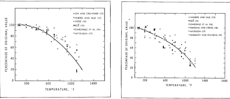
The mechanical properties that most significantly affect the critical temperature of a steel column are modulus o f elasticity ;und yield strength of the steel. Both decrease as temperature increases. Data concerning the dependence of these properties on t e m p e r a t u ~ e have been reported by several authors.' M e a s u ~ e d values of the modulus elastic~ty and the yleld strength of vallous structural carb steels (ASTM A-36, St-37, CSA C40. 12) as a function tempelatitre ale plotted In Figures 5 , ~ n d 6. T h e wlde spre; in the data can be a t t ~ i b u t e d to many factors, the m
important being the variability of steel cliemlcal composit and the Influence of strain late and cleep ploperties on test results.
Curves have already been dlawn20 t o suit a n ana exp~ession as well as the data repol ted in the literature. w ~ l l be used t o evaluate the clitlcal t e m p e ~ a t u r e s o columns and their dependence on column size, shape length. The authors point o u t that the yield btrengtli c u ~ v represents the average decrease with temperature, bu modulus of elasticity culve, because it represents thc l n l p o ~ t a n t variable, is somewhat conservative. The a pllate analytical expressions f o ~ yield stlength ;und rn
of elasticity are:
wherc C, = 30
-
F,/5 b u t not more t h a n 20:but not less than 78
F, - 13 and E = E,(1
-
2.488')respectively. I n the above equations
Figzlre 3. Comples PI-otection.
The following assumptions were made in the calculations: for columns whose p~otectlon does not add significantly to
I ) The column is free to expand duringheating. the strength of the structural unit,complete failure occursat
2) The ~nfluence of creep is neglig~ble at ternperatules below temperatures 5 0 to IOOF deg higher than the temperature at : ~ p p ~ o x ~ m a t e l y 950°F" and will not be separately talten which the column begins to buckle. Consequently, the into account. It should be realized, however, that the 1000°F critical cross-sectional temperature permitted in the presence of creep deformation is already inherent in the current ASTM and CSA stal:dards6 " appeals appropriate
explesslons for ~ n e c h a n ~ c a l p~opertles used in the calcula- because fire tests are not cons~dered terminated until com- tions. plete structural fi~ili~re has o c c u ~ r e d .
3) The stress-stla~n curve at elevated temperatures can be
obtained from a n expresslon s ~ n i ~ l a r to that proposed by Temperature Rise of Protected Steel Columns
~ a l a m b o s ~
'
fol normal bervlce temperatures: The ten~perature rise in a protected steel column IS mast10 rel~ably obtained by conduct~ng a fire test, but ~t can also be
3P
6
=!!
++)
calculated by e n g i n e e ~ ~ n g methods with a reasonable degreeE 7 E F , (6) of acculacy. The proble~ii, onlike fire resista~ice proble~ns
following nlettlod was used to c o ~ i c e ~ n ~ n g more con~plex structural elements, is one ofheat stresses and crllical telnperntllres for steel with condi1ct1011 ; I I I ~ has, over the years, been the subject of various slenderness ratios: several theoretlcnl studies. The following methods al~eady
For stresses below the yield strength of steel the exist to e x p l a ~ n the mechanism of heat transfer from a file bucltl~ng stress F
,,
is given by through insulation to the steel core (see F ~ g u r e l(a)).iWet/zzocl 1 , ong~nally proposed by Geil~nger an d ~ 1 ~ 1 , ~ ~
T' E l assumes one-dimens~onal heat transfer through tlie ~nsula-
li' - -
CI - ( 7 ) t ~ o n . Acco~dingly, the model rep~esenting a protected steel
(I<
'
calumn exposed t o fire 1s a steel plate hav~ng the same weightwhere E~ is the tangent m o d u ~ L l s obtained by differentiatlllg to heated surface area ratlo as the foul s~des o f a unit lengthof equation (6), so that the heated column, protected on the fire s ~ d e and perfectly insulated on the o t h e ~ side. '. The heat capacity of tlie
dF
E , = - = E protective material I S neglected and the temperature gradient
de ~ O ( P / P , ) ~ (8) therein is assumed to be l ~ a e a r . Thermal ~esistance to heat
7 transfer between the fire and an exposed surface is taken ~ n t o
For low slenderness ratios the calculated values of F
,,
will exceed the yield strength of steel. In this case buckling stress is considered to be the yield strength of the steel at the te~nperature under consideration, a temperature that can be determined by means of equa tion (4).Using equations (4) to (8), and assuming values of F y o and E of 36 and 29.000 ltsi respectively, column curves have been calculated for various steel temperatures. These curves are plotted in Figure 7, along with tlie CSA S-I 6 design curves given by equations (1) to (3). The curves show that the critical temperature of the shorter columns isapproximately 880°F and that of intermediate and long c o l u ~ n n s about 950°F. Many fire tests on loaded c o l u ~ n a s ~ 2 - 2 4 ~ndicate ' that,
account, but is i~sually negligible in comparison with the resistance of the protection, for whichconstant vali~esof the tliermal properties are assumed. If desired, the temperature dependence of the heat capacity of steel can be accounted for, but this is i~sually superfluous, considering tlie in- accuracies normally inherent in the assumptions previously made for protection.
il,letllod 2 is the same as method I , with the following
exceptions: the heat capacity of the protection is accounted for by adding one half its value to the heat capacity of the steel core, as proposed by McGuire et al.27 Othershave used " nzis rrlodel has alrencl~~ Deerz erl7plo.vcd with good results it1 calculati~zg the tettlprratttre rise v / i i t ~ p r v t c c t c d steel cohirnns.
T E M P E R A T U R E . F
Y
3
2
Fig~ire 5. Modulus of elasticity of carbon steels asa function
of temperature. OLEA A N D CROUnHER (12) .INBERG A N D SALE (13) ~ V E R S ~ (14) - o G A R O F A L 0 E l AL i l b l - 4 2 'WITTEVEEN (17) - 80
-
0 - (L - - 0 6 0 - - 0 Y - - U u + 4 0 - - 2 Y - U LL 20 - - - - 0 I I I I I I I I Z O O 6 0 0 1 0 0 0 1 4 0 0 1600 w 3 T E M P E R A T U R E . ' FFigure 6. Yield strength of carbon steels as a function of
tenlperature.
I I l l I
' INGBIRG AND SALE (13) m R O ~ (151
OGAROFALO E l AL (161 .SIMMONS AND C W S S (18)
.
WITIEVEEN (171Z AHARM4THY AND STANZAK (I91
; so - - z - 0 u. 6 0 - 0 w -0 2 40 - w U z
:
20 - ,-e ~ p e r i r n e n t . ~ ~
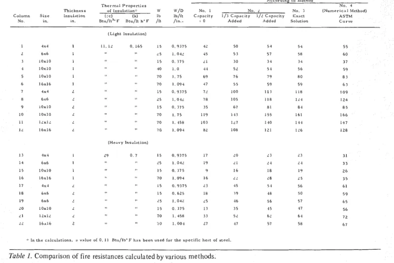
The authors have examined these methods in detail with a heat capacity of steel
view t o determining their relative merits and limitations. A heat capacity of insulation heat capacity of steel
thickness and material properties was e x a m ~ n e d , and the still low compared with the values p ~ o d u c e d results are listed in Table 1 . Both light and heavy protective methods and experiment.
materials were considered.
Calculations were based on an expression that accurately
approximates the ASTM curve3 values obtained by method 4 (numerical) f o r li
T h e r m a l Properties
T h ~ c k n e s s of I n s u l . l t ~ o n \V W/D No I No. L No j ( N u m e r ~ c ~ t 1 M e t h o d ) Colurmn S t z e L n s u l * t ~ o n I:c) ( k ) Ib Ib/it C n p a c ~ t y 1 / 3 C a p r c t t y 1/L C ~ l p a c ~ t y E x d c t A S T M
No I" ~n ~ t u / i t " ~ B t u / i t h 0 F /it / I "
.
- 0 A d d e d Added S o l u t ~ o n C u r v e (Light I n s u l d t , ~ " ) I 4x4 1 I I . 1 L 0 1 6 5 15 0 9 3 7 5 4L 50 5 4 5 4 5 5 L 6 x 6 1 ~ 5 I 04L 45 5 3 57 58 6 0 3 l o x 1 0 I 1 5 0 3 7 5 L I 3 0 34 3 4 3 7 4 1 0 x 1 0 I 40 1 0 .I 4 5 L 5 4 5 6 5 9 5 1 0 x 1 0 1 7 0 1 7 5 6 9 7 6 7 9 8 0 8 3 6 1 6 x 1 6 1 7 0 1 0 9 4 47 5 5 5 9 59 6 3 7 4 x 4 L 15 0 9 3 7 5 7' 1 0 0 I 1 3 118 1 0 9 8 6 x 6 L5 I . O4L 7 8 1 0 5 1 1 8 1 L4 1 2 4 9 1 0 x l O L 1 5 0 3 7 5 3 5 6 7 8 1 8 4 8 5 1 0 1 0 x 1 0 L 7 0 L 7 5 1 1 9 1 4 3 1 5 5 1 6 1 1 6 6 11 l L x l ~ 7 0 1 458 1 0 3 1L7 1 4 0 1 4 4 1 4 7 1 ~ 1 6 x 1 6 L 7 0 1 0 9 4 8L 1 0 8 1 2 1 I L6 1 2 8 ( H e a v y I n s u l . ! t ~ o n ) ': In t h e c a l c u l a t i o n s , ;I v a l u e o i 0 . I 1 B t u / 1 b o F h a s b e e n u s e d f o r t h e s p e c i f i c hein of s t e e l ..
For more dense materials the results ob- Design Formulaeone half of the insluation's capacity or The derivation of the design forlnulae was bas hat lower than those of m e t h o d 4 . examination of the parameters governing the ssumption that the surface temperature temperature during fire exposure. Empirical for
is equal t o the fire telnperature is on the most significant parameters were derived iently satisfied. It can be that be described.
eavy material, i.e., the product kpci large, the One of the ;issumptions common t o all methods :~se ure of the surface will be appreciably lower than the analysis is that heat transmitted through the insulatio
the steel core is equal t o the increase in the heat conten obtained by co sing method 4 are the most realistic, the steel (the heat capacity of air spaces enclosed by accurately known. one-dimensional heat transfer is assumed (methods 1 t o 3
the temperature rise of the steel is given by: should be pointed out that where methods 1 to 3 are
for the solution of fire resistance problems a value can
d T , aTi
ith the aid of a sllde rule or desk c,W
-
= Ak-
at ax
sonably representa-
d often found in the where
re. Application of method 4 requires a high-speed cs = specific heat of steel aterials properties obtainable from = mass of steel per unit lengtll
laboratories, including the authors'. A = area of protection a t the interface between protection able for c a l c ~ ~ l a t i o n s and steel through whlch heat is transferred t o the ving protective materials containing components that steel, per unit length
rgo significant chemical reactions a t elevated tempera- 1, = therlnal c o l l ~ u c t i v i t y of insulation ures, for example, cement paste and gypsum. The change in Ts= steel temperature
h materials, particularly increase in Ti = insulation temperature t in an increased fire resistance. =
heat with tempera- = coordinate perpendicular to insulation surface regular pattern and
representative values at elevated temperatures are often If thermal resistance between the i n s u l a t i o ~ ~ surface and difficult to provide, rendering methods 1 to 3 unsuitable for fire is neglected and a linear temperature gradient tl,rough sdch protective materials. the insulation assumed, it becomes
For lighter materials whose heat capacity is relatively
small, on the other hand, the influence on fire resistance of dTi T J - T ,
changes in heat capacity with temperat~lre is also relatively - = - ax I (13)
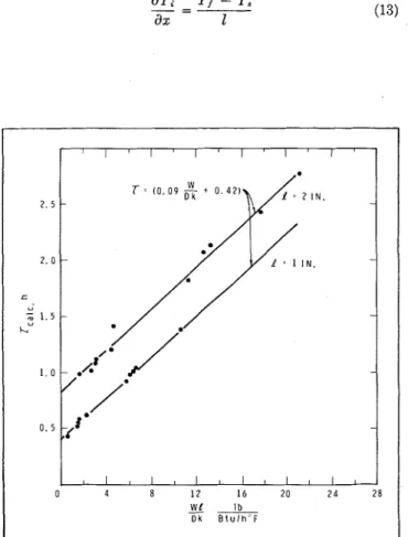
small. By examining the results obtalned by means o f methods 1 t o 4 it was possible t o derive simple forlnulas for the fire resistance of steel columns thus protected. These are accurate enough for most practical purposes, as will be s11owu. 8 4 0 I I I I I I I I 3 5 - - 30 - - - I 0 - 20 40 60 80 100 1 2 0 I 4 0 1 6 0 180 200 S L E N D E R N E S S R A T I O . K L l r
Figure 7. Buckllngstress as a function of the slenderness ratio Figure 8. Calculated fire resistance as a function of WJLIDk for
where Tf = fire temperature attempt was made t o find a ~ e l a t ~ o ~ l between density and Q = tlilckness of insulation thermal c o n d u c t i v ~ t y for use In equation (1.5). F ~ g i u e 9 1s a S u b s t ~ t u t ~ o n In equation (1 2) then y ~ e l d s plot of k versus p and ~ n d ~ c d t e s that t h e two can be
approxlnlately elated by the exp~ession.
c,Wl
= T, - Ta,
--
a
at (14) k = 0 . 0 0 4 6 ~ (16)It should be noted that gypsum b o a ~ d s , whose t h e ~ m a l w h ~ c h shows that the steel temperature is a function of the properties vary llregularly with temperatllre because of parameter WQ/fi, if the specific Is taken as a dehydlation, ale not Inclllded in tile glaplls. Neither 1s
constant. Because the heated area A 1s ploportional t o the equation (16) applicable to polous m l n c l a l wood heated perimeter D, the steel temperature 1s also a fiunct~on witll a density of less
201b/ft3 their
of WQ/Dk. tllermal c o n d u c t ~ v ~ t y ~ n c ~ e a s e s vely rap~dly wl A plot o f the fire resistances obtained by means o f model temperature owing t o radlatlon f l o m fibre to fibre.3s 4 and the ASTM fire curve against the parameter WQ/Dk leference states, howevel, t h a t a ofapploxln,ately ( F i g u ~ e 8 ) shows that this parametel alone cannot 0.15 Btu/ft h
O F can be used In f o ~ m u l a (15) f o ~
sufficiently desc~ibe the fire resistance o f a p ~ o t e c t e d steel c o n ~ l l c t l v l t y of mineral wool density lange to column. This IS not unexpected because the palameter does
lb/ft3. l ~ ~ l l s t l a t e s [hat calltlon slloLlld be applied I not ~ n c l u d e the influence of the heat c a p a c ~ t y of the c o r l e c t Llse of
insulation on the steel temperatule. Adding another G e n e ~ a l l y , light, fibrous, polous materials such a palameter, however, that Is a function of
'
and can wool products will provide lowel f ~ r e res~stances tlt h ~ l s take Into account t o a certain degree Ille lnsulatlon's ca]cll]atetl. Otllers that chellllcal changes (gypsulll, lleat capacity makes it possible t o exPless the compllted cement paste, some ccnclete
01 plaster aggregates) wll]
file res~stance by a single formula: p r o v ~ d e higher file ~ e s ~ s t a n c e . Chem~cally stable materials
(vermiculite, p e ~ l ~ t e , dense mineral wool, asbestos, clay) are
W l expected t o y ~ e l d file ~ e s ~ s t a n c e s very close to those
T = 0.09 DJC
+
Cl, calculated by the deslgn folmula. 0 1 1 s u b s t ~ t u t ~ o nequatlon (16) Into equation (15), t h ~ s becomes:
where C IS a c o n s t a ~ ~ t . As i n d ~ c a t e d , the term CQ takes ~ n t o W l
account the heat capaclty of the insulation and a value o f T = 2 0 - + C l DP
0.42 for C glves a good fit with the computed fire
resistances ( F ~ g u ~ e 8). All p a ~ a m e t e ~ s in this expression can be ~ e a d i l y d e t e ~ m ~ n e All parameters ~n the fo~milla can be d e t e r m ~ n c d readily Using a value of C = 0.43- (which gave t h e best fit wl except the thermal conductivlty of the lnsulation, k, which fire leslhtances compl1ted b y method 4), the acculacy allnost always varies with temperatL1re, ~f a value expressloll (17) was examined by c o m p a r ~ n g calculated fl
o f k Is thelefore, I t sllould be cl,osen so as to r e s ~ s t ; ~ ~ i m s w ~ t h e x p e ~ ~ m e n t a l data flom l a b o ~ a t o r ~ e s in
c h n ~ a c t e ~ ize a p p ~ oxlmately the actual the1 ma1 conductlvlty Bllt"l1 'JFRO), Canada (NRCC j, I-lolland (TNO), Japan a t elevated t e m p e ~ a t l u e s . Such a p p ~ o x ~ n l a t e values ale given (BRI) a n d the United States (ULI). The materials
m
theIn R e f e ~ e n c e s 35 and 36.
Normally, thermal c o ~ i d u c t i v ~ t y inc~eases with density. As density is a q u a n t ~ t y that can be readlly d e t e ~ m l n e d , a n
Fzgo.e 9. A p p ~ o x ~ m a t e thermal c o n d u c t ~ v ~ t y (k) a t elevated Flg~ae 10 Cornpallson between calculated and e x p e l ~ n ~ e n t a l
t e m p e r a t u ~ e s of various materials as a functlon of the11 fire lesistances (calculated from f o ~ m u l a ( 1 8 ) for 11ght and density (p). chern1cally stable p r o t e c t ~ o n s ) .
7 6 0.7 0 6 u. r Z 0 5 -
.
3-
m g 0 4 - > - + V 2 0 3 Z 0 V 2 4 2 0 2 - L L L I I I I ISPRAYED FIBRE [ULI ( 3 7 d
0 VERMICULITE @LC 1389
- -
.
SPRAYED ASBESTOS [TNO (39)l0 VERMICULITE !NO ( 3 9 0 I VERMICULITE @FRO (40)] I 1 I t I I - - - -
/
-CUY BRICK [AUTHORS (NRCC)]
- 1 SPRAYED ASBESTOS ~ U T H O R S (30)] v VERMICULITE [AUTHORS (NRCC)] 4 - c U - rn u - I- 3 - 2 - - - I I I I 0 1 2 3 4 5 6 i r , x p , h + - I I 1 I 0 20 40 60 80 100 120 1 4 0 D E N S I T Y l b l f l 3
tests were for the iiiost part common protective materials Further exa~nination of low-density mineral wool such as ver~niculite, perlite and sprayed fibres with various protections serves rls an e x a ~ n p l e . It has been stated that binders, and mineral wool. One test involved a clay brick. equation ( 1 6 ) and hence equation (17) are n o t valid for Both box and contour type protections were represented. these protections. If the actual therlnal conductivity of k =
The comparison sllows that calculated values of fire 0 . 1 5 Btu/ft 11 O F is used in equation (15), as has been
resistance are in f a ~ r agreement with experimental results, recommended, reasonable agreement with experimental although generally slightly lower for chemically stable data may be obtained for the density range 7 t o 2 0 1b/ft3. materials. As a result, the following expression was chosen
as yielding the most representative answers (Figure 10):
for relat~vely lightweight protectwe materials (p
5
5 0 Ib/ft3 ).For materials that contain cement paste or gypsum, formula ( 1 8 ) plovides conservative answels. Using C
-
1.2 gives good results (Figure 11) and for these materials the expressionshould be used (p L 5 0 lb/ft3).
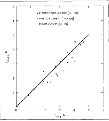
Design formulas (18) and (19) were developed by a semi-empirical approach and offer a far simpler solution to column flre resistance problems than has previously been available. Users should appreciate, however, that because of their generality certain p ~ t f a l l s can be encountered if they are applled to a problem indiscriminately, as has already been illustlated for lninelal wool products. The accuracy o f calculated results can be improved for any matelial by returning t o equatlon (1 5 ) whenever sufficient test data are available.
I I I I I
.
CEMENTITIOUS MIXTURE [ULI 137d n A S B E S T O S CEMENT [TNO (39)l- -
O PERLITE PLASTER [BRI (28)]
-
/
-
-.
D /:* A I I I IFigure 11. Comparison between calculated and experimental
fire resistances (calculated from formula (19) for light pro- tections containing cementitious components).
W ~ t h even lighter products, such as those normally used for sound absorption, a value of k = 0.25 Btu/ft
OF
o r higher was found to be appropriate.An important practical application of the derived formulae is to show how column fire resistance varies with the so-called " s i ~ e and shape" frlctor, WID. This variation is illustrated in Figure 11 for a typical sprayed fibre on varlous commonly used column sections. As rnay be seen, the effect of the "size and shape" factor o n fire endurance is extremely signif~cant and should not be ignored in the deslgn of c o l ~ ~ r n n f ~ r e protection.
Co~lclusion
Means for solviilg fire resistance problems of protected steel colulnns have been presented. All rely o n careful engineering judgment in the choice o f solution and assessment of the confidence level of that solution. With known a n d widely used ~naterials, for which considerable fire test data al-e available, it is suggested that formulae (18) and (19) be incorporated in building regulaiions in the form
whereC = 0.5 - for protections mainly consisting of chemically stable materials such as verniiculite, perlite, sprayed asbestos with various binders, and dense ( p 5 2 0 Ib/ft" mineral wool; C = 1 .? for protections containingcement paste or
gypsurn, such as asbestos-cement board, plasters and cementitious ~nixtures.
Forlnula (20) is valid for relatively light protective materials (p 1 5 0 lb/ft3). M i e n used for heavier materials, it is expected t o give conservative estimates of fire resistance. This paper is a contribution from the Division of Build- ing Research, National Research Council of Canada and is published with the approval of the Director of the Division.
References
I. S t a n z a k , W.W. and Lie, T.T. Fire Resistance of U n p r o t e c t e d Steel Columns. ASCE, Jolrrt~al o f ' t l ~ e Strrlctrrral D i v i s i o t ~ , paper 9 7 1 9 , May 1973. pp. 837-852.
2 . Lie, T.T. a n d T.Z. H a r m a t h y . Fire Resistance o f Concrete I'rotected S t e e l Columns. T o b e published
3. Seigel, L.G. Water-l:illed T u b u l a r Steel C o l u m n s . Fire l'rotection W i t h o u t Coating. Civil E t ~ g i t ~ e e r i r ~ g , V o l . 37, No. 9,
S e p t . 1967, pp. 65-67.
4. Port, L.W., J . J . Keough, a n d 1i.W. Woollett. Water-Filled Steel C o l u m n s f o r Fire I'rotection. l ~ l s t i t u t i o n o f Engineers, Vol. C E I I , No. 2 , Australia, O c t . 1969.
5 . Standard Specifications for Fire Tests o f Materials and Constructions. ASTM C 19-26T, 1926.
6. Standard M e t h o d s of Fire T e s t s of Building C o n s t r u c t i o n and Materials. ASTM E l 19-7 1 , 1 9 7 1 B o o k o f ' A S T A ~ S t a r ~ d a r d s , Part
1 4 , pp. 431-448.
7 . Steel S t r u c t u r e s for Buildings. CSA S t a n d a r d S16-1969, Canadian S t a n d a r d s Association, 1969.
8. Canadian S t r u c t u r a l Design Manual. Supplement N o . 4 to the Nation;~l Building Code of C a n a d a , National Research Council of Canada, 1970, p. 371 ( N R C C 11530)
Allowable S t r e i d l y - L o a d e d S t e e l o n o f S t r u c t u r a l
Wiley & S o n s , Inc., N e w Y o r k , 1 9 6 6 , p. 3 6 ,
12. Lea, F.C. a n d O.H. C r o w t h e r . T h e C h a n g e o f t h e M o d u l u s o f
E l a s t i c ~ t y a n d of O t h e r P r o p e r t i e s of Metals w i t h T e m p e r a t u r e . P r o t e c t e d w t t h Vtculad Panels. Depart E ~ ~ g i n e e ~ i ~ z g , V o l . 9 8 , 1 9 1 4 , p. 4 8 7 . Industrial Research a n d Fire Offices' 1 3 . Ingberg, S.H. a n d P.D. Sale. Compresstve S t r e n g t h a n d Research O r g a n i z a t t o n . U n p u b l i s h e d test
D e f o r m a t i o n o f S t r u c t u r a l Steel a n d C a s t - I r o n S h a p e s a t T e m p e r a t u r e s u p t o 9 5 0 ' ~ ( 1 7 4 2 ' ~ ) . Proceedir2gs o f the A m e n c a m Society for Testing and Materials, Vol. 2 6 , 11, 1 9 2 6 , p. 3 3 .
14. Versg, G. T h e Elasttc P r o p e r t i e s o f S t e e l a t High T e m p e r a t u r e s .
T r a n s a c t i o n s , A m e r t c z n S o c i e t y o f Mechanical Engineers, Vol. Nomenclature 5 7 , 1 9 3 5 , p. 1.
15. Ros, M. Feuersicherheit u n d Feuerscliutz d e r S t a h l k o n s t r u k - Notatiotzs t i o n e n . G u t a c h t e n e r s t a t t e t an die T e c h n i s c h e Kommission d e s
V e r b a n d e s Schweizertscher Bri'clembau-und S t a h l h o c h b a u - a thermal diffusivity, f t 2 /h U n t e r n e h m u n g e n , Z u r i c h , 1 9 4 7 . c specific heat, Btu/lb OF
1 6 . G a r o f a l o , E., P.R. M a l c n o c k , a n d G.V. S m ~ t h . T h e I n f l u e n c e o f C constant taking into account t h e h e a t c a p a c i T e m p e r a t u r e o n t h e Elastlc C o n s t a n t s of S o m e C o m m e r c ~ a l
Steels, D e t e r m i n a t i o n o f E l a s t ~ c C o n s t a n t s . A S T M S T P 1 2 9 , ti0n A m e r i c a n S o c i e t y f o r Testtng a n d Materials, 1 9 5 2 , p . 10.
17. Witteveen, J . B r a n d v e t l ~ g h e t d S t a a l c o n s t r u c t i e s , C e n t r u m B o u w e n in Staal. R o t t e r d a m , 1 9 6 6 .
1 8 S ~ r n m o n s , W.F. a n d C C . H o w a r d . E l e v a t e d - T e m p e r a t u r e Proper- through whichheat is transferred tosteel) ttes o f C a r b o n Steels. A S T M Speclal Technlcdl Publication No. E ofelasticity,ksi
1 8 0 , A m e r i c a n S o c i e t y f o r Testing a n d Materials, Phtladelplita, 1 9 5 5 .
a n d C r e e p P r o p e r t ~ e s o f S o m e S t r u c t u r a l a n d Prestressing Steels. K effective length factor A m e r i c a n S o c i e t y f o r T e s t i n g a n d Materials, Speclal T e c h n ~ c a l
Publlcdtion 4 6 4 , 1 9 7 0 , p. 1 8 6 . 1 thickness of insulation, in. 2 0 . Lie, T.T. a n d D.E. Allen. Calculation o f t h e Fire Resistance o f L height of column, ft
R e i n f o r c e d C o n c r e t e C o l u m n s . N a t i o n a l Research Council o f
C a n a d a , D i v ~ s ~ o t i o f Building Research. N R C C 1 2 7 9 7 , August r radius of gyration, f t
1 9 7 2 . t time, h r
2 1. G a l a m b o s , T.V. S t r u c t u r a l M e m b e r s a n d F r a m e s , Prentice-Hall, T Temperature, O F
Inc.. E n g l e w o o d Cliffs. N J . 1 9 6 8 .
2 2 . Mitchell, N.D. Fire T e \ t s o f C o l u m n s P r o t e c t e d w i t h G y p s u m , steel section per f t l
lblft
Research Paper R P 5 6 3 , Bureau o f S t a n d a r d s , J o u r n a l o f R e - x coordinate perpendicular t o insulation surface s e a r c h , V o l . 1 0 , J u n e 1 9 3 3 .
2 3 . Ingberg, S.H., H.K. Griffin, W.C. R o b i n s o n , a n d R.E. Wilson. Fires T e s t s o f Building C o l u m n s . T e c h n o l o g i c Papers o f t h e Bureau o f S t a n d a r d s , No. 1 8 4 , U.S. D e p a r t m e n t o f C o m m e r c e ,
National Bureau of S t a n d a r d s . Washineton. 1 9 2 1. Greek Letters 2 4 . A s h t o n , L.A. a n d N. D a v e y . ' F i r e ~ e i t s o f S t e e l C o l u m n s f r o m
"lnvestigatioti o f Building Fires. Part V. 1:ire T e s t s o f S t r u c t u r a l Elements". National Building S t u d i e s , Research Papcr No. 1 2 , H.M. S t a t i o n e r y Office, L o n d o n , 1 9 5 3 .
2 5 . M e t h o d s o f Fire T e s t s o f WaIls,Pnrtitions, F l o o r s , Roofs, Ceilings. C o l u m n s , Beams a n d Girders. C S A S t a n d a r d 8 5 4 . 3 - 1 9 6 4 , Cnnn- dian S t a n d a r d s Association, O t t a w : ~ , 1 9 6 4 .
2 6 . Geilinger. W. a n d S . Bryl. I-euersicherheit d e r S t a h l k o n s t r u k s - t i o n e n , IV Tei1:Feuerschutz von S t a h l s t u t z e n . Verlag Scliweizer S t a h l b a u v e r b a n d . Zurich. 1 9 6 2 .
2 7 . McGuire, J.H., W.W. S t a n z a k , a n d M. Law. T h e Scaling o f Fire Resistance Problems. In p r e p a r a t i o n .
2 8 . Fujii, S . T h e T h e o r e t i c a l Calculation o f T e m p e r a t u r e - R i s e o f T h e r m a l l y P r o t e c t e d S t e e l C o l u m n E x p o s e d t o t h e I.'ire. Building Research Institute. 0ccasion:ll R e p o r t No. 1 0 , T o k y o , 1 9 6 3 . 29. Pettersson, 0 . Utvecklingstendenser r o r a n d e b r a n d t e k n i s k
a fraction of insulation capacity added to t h a t of steel
E strain, in/in. p density of insulation, l b / f t 3 T fire resistance, h Subscripts a allowable cr critical f of fire i of insulation d i m e n s i o n e r i n g av ~ t a l k o n s t r u k t i o n e r . Vag-och vattenb)>ggarerz, o a t room temperature No. 6 - 7 , S t o c k h o l m , 1 9 6 4 , p p . 2 6 5 - 2 6 8 .
3 0 . Lie. T . T . T e m o e r a t u r e of P r o t e c t e d S t e e l in Fire. Paoer 8 o f "Behaviour of S t r u c t u r a l Steel in Fire," Ministry o f T e c h n o l o g y a n d Fire Offices' C o m m i t t e e , J o i n t Fire R e s e a r c h O r g a n i z a t i o n . S y m p o s i u m No. 2 , H.M.S.O., L o n d o n . 1 9 6 8 .
3 1. Lie, T.T. a n d T.Z. H a r m a t h y . A Numerical P r o c e d u r e t o Calculate t h e T e m p e r a t u r e o f l'rotected S t e e l C o l u m n s E x p o s e d t o Fire. National Research Council o f C a n a d a , 1)ivision o f Building Research. M R C C 1 2 5 3 5 , March 1 9 7 2 .
3 2 . Williams-Leir, (;. A n a l y t i c Equivalents o f S t a n d a r d Fire T e m p e r a - t u r e Curves. Fire Techr~olog)), Vol. 9 , No. 2. May 1 9 7 3
3 3 . Grave, A. d e a n d G.A. H e r p o l . La Resistance a u F e u d e s E l 6 m e n t s d e C o n s t r u c t i o n . C e n t r e S c i e n t i f i q u u et T e c h n i q u e d e la C o n - s t r u c t i o n , Bruxelles. 1 9 7 1 .
3 4 . Witteveen, J . Brandveiligheid S t a a l c o n s t r u c t i e s , C e n t r u m B o u w e n in S t a a l , R o t t e r d a m , 1 9 6 6 .
3 5 . Lie, T.T. Fire a n d Buildings. Applied S c i e n c e Publishers Ltd., L o n d o n , J a n u a r y 1 9 7 2 .
3 6 . Bereclinung d e s B r a n d w i d e r s t a n d e s von S t a h l k o n s t r u k t i o n e n . Schweizerisclien Zentralstellr f u r S t a h l b n u , Z u r i c h , 1 9 6 9 .
t tangent y yield
of Building Research of the National Research Council of Canada. I t should not be reproduced in whole or in part without permission of the original publisher. The Division would be glad to be of assistance in obtaining such permission. Publications of the Division may be obtained by mailing the appropriate remittance (a Bank, Express, or Post Office Money Order, or a cheque, made payable to the Receiver General of Canada, credit NRC) to the National Research Council of Canada, Ottawa. K1 A OR6. Stamps are not acceptable.
A list of all publications of the Division is available and may be obtained from the Publications Section, Division of Building Research, National Research Council of Canada, Ottawa. KIA OR6.