HAL Id: tel-01677896
https://tel.archives-ouvertes.fr/tel-01677896
Submitted on 8 Jan 2018HAL is a multi-disciplinary open access archive for the deposit and dissemination of sci-entific research documents, whether they are pub-lished or not. The documents may come from teaching and research institutions in France or abroad, or from public or private research centers.
L’archive ouverte pluridisciplinaire HAL, est destinée au dépôt et à la diffusion de documents scientifiques de niveau recherche, publiés ou non, émanant des établissements d’enseignement et de recherche français ou étrangers, des laboratoires publics ou privés.
Myriana Rifai
To cite this version:
Myriana Rifai. Next-generation SDN based virtualized networks. Other [cs.OH]. Université Côte d’Azur, 2017. English. �NNT : 2017AZUR4072�. �tel-01677896�
Research Team: SIS-SigNet
PhD Thesis
to obtain the title of Docteur en Informatique de l’Université de Côte d’Azur
by
Myriana RIFAI
Next-Generation SDN Based Virtualized
Networks
Directed by: Guillaume URVOY-KELLER Co-supervised by: Dino LOPEZ-PACHECO Defended on 25 September 2017
Jury Members:
Dino Lopez-Pacheco Maître de Conférences, Université de Côte d’Azur, France Co-supervisor Guillaume Urvoy-Keller Professor, Université de Côte d’Azur, France Thesis Director Laurent Mathy Professor, Université de Liège, Belgium Reporter Mathieu Bouet Research Team Leader, Thales Communications & Security, France Examinator Pietro Michiardi Professor, Eurecom, France Reporter Thierry Turletti Researcher, INRIA Sophia Antipolis, France Examinator Yin Zhang Staff Software Engineer, Facebook, USA Examinator
Software Defined Networking (SDN) was created to provide network programmability and ease complex configuration. Though SDN enhances network performance, it still faces multiple lim-itations. In this thesis, we build solutions that form a first step towards creating next-generation SDN based networks.
In the first part, we present MINNIEto scale the number of rules of SDN switches far beyond the few thousand rules commonly available in Ternary Content Addressable Memory (TCAM), which permits to handle typical data center traffic at very fine grain. To do so MINNIEdynamically compresses the routing rules installed in the TCAM, increasing the number of rules that can be installed.
In the second part, we tackle the degraded performance of short flows and present our coarse grained scheduling prototype that leverages Software Defined Networking (SDN) switch statistics to decrease their end-to-end delay. Then, we aim at decreasing the 50ms failure protection interval which is not adapted anymore to current broadband speeds and can lead to degraded Quality of Experience (QoE). Our solution, PRoPHYS, leverages the switch statistics in hybrid networks to anticipate link failures drastically decreasing the number of packets lost.
Finally, we tackle the greening problem where often energy efficiency comes at the cost of performance degradation. We present SENAtoR, our solution that leverages SDN nodes in hybrid networks to turn off network devices without hindering the network performance. Finally, we present SEaMLESS that converts idle virtual machine (VM) into virtual network function (VNF) to enable the administrator to further consolidate the data center by turning off more physical server and reuse resources (e.g. RAM) that are otherwise monopolized.
Keywords: SDN, TCAM, Scalability, Hybrid Networks, Performance, Scheduling, Resilience, Energy Efficiency, Service Availability
Les réseaux logiciels "Software Defined Networking (SDN)" permettent la programmation du réseau et facilitent sa configuration. Bien que SDN puisse améliorer les performances, il reste confronté à de multiples défis. Dans cette thèse, nous avons développé des solutions qui con-stituent un premier pas vers les réseaux SDN de prochaine génération.
D’abord, nous présentons MINNIE qui permet la scalabilité des commutateurs SDN, qui ne supportent que quelques milliers de règles dans leur coûteuse mémoire TCAM. MINNIE com-prime dynamiquement les règles de routage installées dans le TCAM, augmentant ainsi le nombre de règles pouvant être installées.
Ensuite, nous abordons le problème de la dégradation de performance des flux courts avec un prototype d’ordonnancement qui exploite les statistiques des commutateurs pour diminuer leur délai de bout-en-bout. Puis, nous visons à diminuer l’intervalle de protection de 50ms qui n’est plus adapté aux applications modernes et réduit leur qualité d’expérience. Notre solution PRo-PHYS s’appuie sur les statistiques des commutateurs dans les réseaux hybrides pour découvrir les pannes de liens plus vite que les solutions existantes.
Enfin, nous abordons le problème de l’efficacité énergétique qui souvent mène à une dégrada-tion de performance. Nous présentons SENAtoR, qui exploite les nœuds SDN en réseaux hybrides pour éteindre les noeuds réseau sans entraver la performance. Également, nous présentons SEaM-LESS qui convertit le service fourni par une machine virtuelle inactive en une fonction de réseau virtuelles pour permettre à l’administrateur d’utiliser les ressources bloquées tout en maintenant la disponibilité du service.
Mots clés: SDN, TCAM, Scalabilité, Réseaux Hybrides, Performance, Ordonnancement, Résilience, Efficacité Énergétique, Disponibilité des Services
First, I want to thank my supervisors Prof. Guillaume Urvoy-Keller and Mr. Dino Pacheco Lopez for believing in me and for all the help, guidance, support and encouragement that they have offered me during my stay at I3S lab. Working with my professors was a real pleasure, as they were constantly supporting me and they have managed to provide a friendly environment which allowed me to prosper and develop my skills, as well as bypass my flaws.
I also sincerely thank all my friends and colleagues in the SIS team for their support and the nourishing friendly environment that they have provided in I3S lab. It was very nice working with you.
Moreover, I thank the members of the COATI team Joanna Moulierac, Frederic Giroire, Nico-las Huin and Christelle Caillouet and Signet team Engineer Quentin Jacquemart for their cooper-ation, help and support during the projects that we conducted together.
And, I deeply thank prof. Yusheng Ji for hosting me in her lab at the National Institute of Informatics and for guiding me and providing me with everything I needed during my internship in Tokyo, Japan.
I also thank my parents, grandparents and brother for their help during all the previous years. I would not have been here if it was not for their financial help, their encouragement to develop, prosper, and follow my dreams.
Finally, I dedicate this thesis to my fiancée Majdi Kharroubi and thank him for all his support and encouragement during my PhD years. In particular, I want to thank him for the inspiration that he provided me which allowed me to solve the complex problems that I was faced with during my PhD years, and for his patience when I had to work all day long non-stop.
Les réseaux, tels que les réseaux des centres de données (en anglais Data Center "DC") et les fournisseurs d’accès Internet (en anglais Internet Service Provider "ISP"), sont généralement com-posés de multiples périphériques réseau hétérogènes comme les commutateurs, les routeurs, les pare-feux, etc. Dans les centres de données, les périphériques réseau sont généralement situés dans la même zone géographique et fourni multiples services. D’autre part, les périphériques réseau dans les réseaux ISP, également appelés réseaux backbone, sont dispersés géographiquement au-tour d’un pays ou d’un continent et génèrent une énorme quantité de trafic. Dans les réseaux traditionnels, ces périphériques réseau doivent être configurés individuellement par les adminis-trateurs réseau utilisant l’interface de ligne de commande (en anglais Command Line Interface "CLI") pour fournir la configuration requise pour appliquer la politique définie. Ce processus est très difficile à gérer, puisque les politiques de réseau sont de plus en plus complexes et parfois restreints par le fournisseur de périphérique réseau [BAM09]. De plus, la complexité de la con-figuration, l’augmentation de la variabilité du trafic et de la dynamique du réseau a poussé vers la nécessité d’avoir des réseaux programmables qui permettront aux administrateurs de program-mer les périphériques pour leur permettre de prendre des mesures automatiquement sur certains événements [NMN+14]. Afin de résoudre tous les problèmes mentionnés auparavant, les réseaux définis par les logiciels ( en anglais appelé Software Defined Network "SDN") ont été créés.
SDN est une nouvelle architecture de réseau prometteuse et hautement flexible qui surmonte les limites des mécanismes d’acheminement des réseaux basés sur le protocole Internet (abrégé en IP) existants. En effet, les réseaux SDN peuvent non seulement utiliser l’adresse de destination IP pour prendre des décisions d’acheminement, comme les réseaux IP traditionnelles, mais peuvent également utiliser plusieurs autres informations de l’en-tête de paquets niveau couche de liaison de données, réseau et transport [MAB+08]. Les technologies SDN font également une séparation nette entre le plan de commande et le plan de données où les deux plans sont physiquement séparés. Le plan de données est matérialisé par les commutateurs, et le plan de commande est déplacé vers une entité centralisée, le contrôleur (Figure 0.2). Dans les réseaux SDN, les commutateurs SDN sont considérés comme des périphériques qui ne suivent que les politiques de transfert dictées par une entité programmable externe: le contrôleur, qui implémente le plan de contrôle (Figure 0.1). Ainsi, il n’est plus nécessaire d’avoir plusieurs périphériques réseau en boîte noire avec des fonctions de réseau spécifiques telles que les commutateurs, les routeurs, les pare-feux, etc. De plus, il n’est plus nécessaire d’exécuter une commande pour configurer des périphériques réseau
propagera les règles d’acheminement à tous les équipements SDN [HPO13].
La création de SDN qui permet la centralisation du plan de contrôle, la vue globale du réseau et la programmabilité du réseau offre la possibilité de créer de nouveaux services qui permettent d’améliorer les performances des réseaux traditionnels et de contourner leurs limites et restric-tions. Cependant, SDN est une nouvelle architecture de réseau évolutive qui en est encore à ses balbutiements. Pour permettre sa maturité et le déploiement complet des réseaux SDN, plusieurs sujets de recherche, y compris la conception, la scalabilité et la résilience des commutateurs et des contrôleurs, sont encore en cours d’étude [KREV+15].
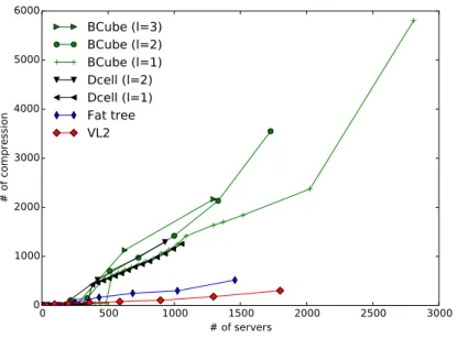
Dans cette thèse, nous abordons d’abord le problème de scalabilité des commutateurs SDN. Le principal problème qui se pose ici, c’est que les commutateurs SDN utilisent la mémoire ter-naire adressable par contenu (en anglais Ternary Content-Addressable Memory "TCAM") pour en-registrer les règles de transfert et fournir les meilleures performances. Cependant, cette mémoire est à la fois coûteuse et consomme trop d’énergie. Pour résoudre ce problème, nous avons créé une solution appelée MINNIE. MINNIE est une solution construite en tant que module du contrôleur Beacon qui maximise l’utilisation de l’espace TCAM. Lorsque la limite TCAM est atteinte sur un nœud SDN, MINNIE comprime automatiquement du côté du contrôleur la table d’envoi du périphérique SDN concerné, en fonction des adresses IP source ou destination. Ensuite, MINNIE transmet la nouvelle table de routage compressée au périphérique SDN pour remplacer l’ancienne table de routage qui a utilisé l’espace SDN complet. À l’aide d’expérimentations, nous prouvons que MINNIE fourni un taux de compression entre 71% et 97% quelle que soit la topologie DC (Figure 0.3) et n’a pas d’impact négatif sur les performances du réseau. Nous avons également prouvé numériquement, que la durée de compression de MINNIE est de l’ordre de quelques mil-lisecondes. MINNIE peut compressé des millions des règles et la plupart des topologies de réseau peuvent installer toutes leurs règles avec un espace TCAM de 1000 règles.
Ensuite, dans la deuxième partie de cette thèse, nous utilisons des dispositifs SDN pour améliorer la performance des flux. Dans cette partie, nous tirons parti de la centralité du contrôleur et de la programmation du réseau, et créons d’abord un nouveau prototype d’ordonnancement qui peut détecter dynamiquement les flux longs dans le réseau et les deprioritiser sans modifier les hôtes finaux ou les périphériques réseau. Ensuite, nous créons une deuxième solution nommée PRoPHYS: Providing Resilient Path in HYbrid Sdn qui vise à fournir un chemin résilient dans un réseau SDN hybride. PRoPHYS insère des périphériques SDN dans les réseaux traditionnelles pour créer des réseaux hybrides afin d’améliorer la résilience des flux en détectant les défaillances de liens qui sont connectées à des nœuds SDN ou des routeurs traditionnels avant qu’ils ne soient déclarés comme tels par le périphérique voisin. Cette méthodologie permet ainsi de diminuer le nombre de paquets et connexions perdus lors du reroutage du flux avant que les pannes de liaison ne soient déclarées.
0 500 1000 1500 2000 2500 3000 # of servers 0.5 0.6 0.7 0.8 0.9 Compression ratio
BCube (l=3)
BCube (l=2)
BCube (l=1)
Dcell (l=2)
Dcell (l=1)
Fat tree
VL2
Figure 0.3: Taux de compression de MINNIE.
grands flux. Notre prototype comporte deux ordonnanceurs: (i) à état et (ii) sans état. L’ordonnanceur à état détecte des gros flux en extrayant les statistiques de chaque flux des périphériques SDN. D’autre part, l’ordonnanceur sans état surveille d’abord l’utilisation de la bande passante du client. Ensuite, lorsque l’utilisation du trafic client est supérieure à son seuil de bande passante prédéfini, l’ordonnanceur zoome dans le trafic du client et utilise l’ordonnanceur à état pour détecter les grands flux (Figure 0.4). Les grands flux sont détectés en surveillant le nombre de paquets trans-mis de chaque flux. Tout flux qui a transtrans-mis plus que le seuil de paquets défini par l’administrateur (par exemple 100 paquets) est considéré comme un flux grand. Après avoir détecté les gros flux, ce prototype - dans les deux variantes - change la priorité des grands flux (passe de la file d’attente de priorité la plus élevée à la file d’attente de priorité la plus basse) afin de permettre aux flux courts de se terminer rapidement. Les résultats des tests ont montré que cette solution était efficace sur les petites topologies linéaires, où tous les flux courts ont réussi à se terminer rapidement. Cepen-dant, ces ordonnanceurs ont offerts de moins bonnes performances sur les topologies de l’arbre et des VL2 (Figure 0.5). Pour cette raison, nous avons abandonné cette piste d’étude et nous avons capitalisé sur le savoir acquis dans cette étude pour l’étude suivante qui porte sur la résilience des réseaux SDN hybrides.
En effet après avoir exploité la centralité du contrôleur pour améliorer la performance du réseau, nous l’avons exploité pour améliorer la résilience du réseau. Pour fournir de la résilience, notre solution PRoPHYS, dispose de deux méthodes pour améliorer la résilience du réseau en diminuant le temps de détection de la défaillance de la liaison dans les réseaux hybrides SDN. La première méthodologie estime le dysfonctionnement d’une liaison en détectant les divergences entre les statistiques des ports transmis et reçus du même ensemble de flux sur les nœuds SDN. Cette méthodologie construit d’abord une matrice de ports communicants. On surveille ensuite les statistiques transmises et reçues de cet ensemble de ports au niveau du contrôleur. Une fois
(b)Étape 2
Figure 0.4: Ordonnanceur à état.
Figure 0.5: Réseau VL2.
Intermediate
Aggregation ToR
de réseau. Cette méthodologie a permis de réduire l’intervalle de détection de défaillance de liaison/nœud réseau de 50%. La deuxième méthodologie utilisée par PRoPHYS dépend de la transmission d’un paquet sonde de suivi du chemin issu du contrôleur (Figure 0.6), au lieu des commutateurs, ce qui diminue la surcharge des processeurs généraux (non dédiés au transfert de paquets entre interface) dans les commutateurs. Cette méthodologie est plus rapide que les méthodes traditionnelles de détection de panne telles que la détection de transfert bidirectionnel (en anglais Bidirectional Forwarding Detection "BFD") car elle détecte une défaillance de lien ou de segment une fois que le paquet n’est pas reçu après un délai d’attente moyen dynamique calculé en fonction du délai réel entre les nœuds au lieu d’un délai d’attente fixe. Nos simulations utisant la topologie dans Figure 0.7 prouvent que cette méthodologie a également permis de réduire de 50% le nombre de pertes de paquets par rapport aux méthodes classiques de détection des pannes. Les deux méthodologies (envoi de paquets sondes et suivi des statistiques) ont permis de maintenir les connexions vivantes malgré les pannes introduises.
La dernière partie de cette thèse est consacrée à résoudre le problème de l’efficacité én-ergétique des réseaux actuels, où l’efficacité énén-ergétique vient habituellement au détriment de la performance du réseau. La première solution que nous proposons est appelée SENAtoR (en anglais Smooth ENergy Aware Routing). SENAtoR utilise les nœuds SDN pour désactiver les pé-riphériques réseau sans perdre des paquets lors de la désactivation des liens, des pannes de liens ou lorsque des pics de trafic se produisent. La deuxième solution que nous proposons dans cette section s’appelle SEaMLESS. SEaMLESS transforme les services des machines virtuelles VMs inactifs en fonctions virtuelles des réseaux (en anglais Virtual Network Functions "VNFs") dans le but de maintenir les services disponibles tout le temps, permettre une meilleure consolidation de serveur (c’est à dire augmenter le nombre de machines virtuelles hébergées par serveur physique), et la libération de mémoire utilisée par la machine virtuelle– puisque la mémoire est la ressource rare dans les centres de données et les nuages d’entreprise (private cloud).
SENAtoR est une solution éconergétique pour les réseaux hybrides de backbone développés conjointement avec l’équipe COATI. Comme pour les algorithmes de routage compatibles avec l’énergie, SENAtoR éteint/allume les périphériques SDN en fonction du trafic. SENAtoR à permet en plus de préserver les performances du réseau et d’éviter les pertes de paquets lorsque des pannes soudaines ou des pics de trafic se produisent (Figure ??). Tout d’abord, pour éviter les pertes de paquets lors de l’arrêt des périphériques réseau, SENAtoR demande au contrôleur d’arrêter d’envoyer des paquets OSPF hello du commutateur SDN à ses périphériques OSPF voisins, une fois que le commutateur SDN doit être éteint ou mis en mode veille. Après, une durée supérieure à la période de détection et de convergence des pannes en OSPF, le contrôleur met le commu-tateur SDN correspondant en mode veille qui permet d’économiser de l’énergie sans perdre les règles d’acheminement précédemment installées dans la mémoire vive (TCAM en l’occurrence). Deuxièmement, SENAtoR surveille le trafic réseau pour détecter les éventuelles défaillances de la liaison ou les pointes de trafic soudaines lorsque les nœuds SDN sont désactivés. Si des
défail-lances de liaison/nœud sont découvertes ou si des pics de trafic apparaissent, SENAtoR sort de leurs état de veille tous nœuds SDN précédemment désactivés pour empêcher la déconnexion du réseau ou la perte des paquets de données. Troisièmement, SENAtoR utilise des tunnels pour ren-voyer le trafic des voisins des nœuds SDN vers la destination correcte pour empêcher les boucles de routage en raison des différences dans la table de routage des nœuds OSPF (en anglais Open Shortest Path First) et SDN.
SEaMLESS est une solution créée par l’équipe Signet à laquelle j’ai participé qui résout le problème des VMs inactives dans les datacenters actuels et les nuages d’entreprise. Le prob-lème consiste principalement à libérer toutes les ressources utilisées (par exemple, la mémoire et l’énergie) tout en maintenant la disponibilité du service fourni. Afin de libérer la mémoire utilisée par ces machines virtuelles et de permettre une consolidation optimisée des serveurs, SEaMLESS migre le processus passerelle des VMs inactives vers un fonction de réseau virtuel (VNF) qui permet d’éteindre la machine virtuelle VM tout en maintenant ses services accessibles (Figure 0.9). Lorsque les utilisateurs essaient de se connecter à ce service, la VNF établit la connexion en premier, puis, en cas d’une tentative d’accès aux données du VM, le contrôleur de SEaMLESS redémarre la VM inactive et la VNF fait migrer la session vers la VM pour qu’elle soit traitée. Cela permet ainsi une disponibilité de 100% des services VM dans les data centers et les nuages d’entreprise tout en optimisant l’utilisation de la mémoire et des ressources énergétiques. Nos résultats montrent que la suspension de la VM inactive, même sans la reconsolidation du serveur, permet d’économiser entre 5 % et 10 % d’énergie. De plus, des dizaines de VNF peuvent être déployés dans 1 Go de mémoire vive (appelé en anglais Random Access Memory "RAM") au lieu de 1 ou 2 machines virtuelles selon les pratiques habituelles de dimensionnement dans les serveurs virtualisés.
À la fin de cette thèse, nous analysons les limites de chaque solution et leurs extensions possibles. Nous indiquons principalement la nécessité de tester toutes les solutions fournies dans un véritable scénario de réseau à grande échelle pour tester l’efficacité de chaque solution. De
Orchestrator Sink Server Sink VNF 2 Sink VNF 1 Sink VNF 3 Server VM 2 VM 1 VM 3 Step 1 Step 5 Step 6 Step 2 Step 3 Step 4 Step 5 Step 4
Figure 0.9: Procédure de migration d’une machine virtuelles a un Sink Server
plus, nous conseillons de développer une extension du schéma de routage couche 3 du SDN aux périphériques existants pour permettre la même vue réseau sur SDN et les périphériques existants dans des réseaux hybrides.
Enfin, nos études ont montré que SDN peut être utilisé pour améliorer les performances actuelles des ISP, du centre de données et du cloud et de l’efficacité énergétique. SDN pour-rait aller plus loin avec l’analyse de réseau temps réel et la modification dynamique à l’aide de techniques d’intelligence artificielle.
Abstract iii
Résumé v
Acknowledgments vii
Résumé Étendue ix
Contents xix
List of Figures xxiii
List of Tables xxvii
1 Introduction 1
1.1 Software Defined Networking . . . 2
1.1.1 Mode of Action . . . 2
1.1.2 Main Components . . . 3
1.1.2.1 SDN Forwarding devices . . . 3
1.1.2.2 Southbound Interface . . . 4
1.1.2.3 Controller Server . . . 5
1.1.3 Migration from Legacy to SDN Networks . . . 6
1.2 Contributions . . . 7
1.3 Roadmap . . . 8
1.4 List of Publications . . . 10
2 State of the Art 11 2.1 Attempts to Overcome SDN Challenges . . . 12
2.1.1 Control Plane Scalability . . . 13
2.1.2 Resilience . . . 14
2.1.3 Multiple Switch Designs Interactivity . . . 15
2.1.4 Flow Table Capacity . . . 15
2.1.5 Switch Performance . . . 16
2.2.1 SDN in hybrid networks . . . 17
2.2.2 Traffic Engineering and Energy Efficiency . . . 18
2.2.3 Resilience . . . 19
2.2.4 Network Virtualization and Management . . . 20
2.3 Conclusion . . . 20
3 Flow Scalability: Minnie 23 3.1 Related work . . . 25
3.2 Motivation: Software vs. hardware rules . . . 26
3.3 Description of MINNIEalgorithm . . . 27
3.3.1 MINNIE: compression module . . . 30
3.3.2 MINNIE: routing module . . . 31
3.4 Implementation: MINNIEin SDN controller . . . 35
3.5 Experimental results using an SDN testbed . . . 36
3.5.1 TestBed description . . . 36
3.5.2 The need of level-0 OvS . . . 37
3.5.3 Number of clients chosen for the experimentations . . . 38
3.5.4 Experimental scenarios . . . 39
3.5.4.1 Traffic pattern . . . 40
3.5.5 Experimental results . . . 41
3.5.5.1 Scenario 1: Compression with LLS . . . 41
3.5.5.2 Scenario 2: compression with HLS . . . 49
3.6 Simulations scalability results . . . 52
3.6.1 Simulation settings . . . 53
3.6.1.1 Scenarios . . . 53
3.6.1.2 Data center architectures . . . 53
3.6.2 Simulation results . . . 56
3.6.2.1 Efficiency of the compression module . . . 56
3.6.2.2 Efficiency of MINNIE . . . 57
3.6.2.3 Comparison of MINNIEeffect on topologies with 1000 servers 60 3.6.2.4 Comparison with XPath . . . 61
3.7 Discussion . . . 62
3.8 Conclusion . . . 65
3.9 Publications . . . 65
4 Performance 67 4.1 Control Plane Centrality . . . 68
4.2 Coarse-grained Scheduling . . . 68
4.2.1 Related Work . . . 69
4.2.2 Scheduling Methodologies . . . 71
4.2.3 Results . . . 72
4.3 PRoPHYS: Enhancing Network Resilience using SDN . . . 77 4.3.1 Related Work . . . 79 4.3.1.1 Hybrid SDN Networks . . . 79 4.3.1.2 Total Downtime and Rerouting . . . 79 4.3.2 Passive Probing Failure Detection Methodology . . . 80 4.3.2.1 Matrix of Communicating SDN Ports . . . 81 4.3.2.2 SDN Ports Monitoring . . . 81 4.3.2.3 Failure Detection Module . . . 82 4.3.3 Active Probing Failure Detection Methodology . . . 83 4.3.4 Rerouting . . . 84 4.3.5 Performance Evaluation . . . 85 4.3.5.1 Impact on Network Traffic . . . 87 4.3.5.2 Impact of the Segment Delay on PortStats . . . 90 4.3.6 Discussion . . . 91 4.4 Conclusion . . . 92 4.5 Publications . . . 94 5 Energy Efficiency 95 5.1 Related Work . . . 97 5.1.1 Backbone Networks . . . 97 5.1.2 Data Center . . . 98 5.2 SENAtoR: Reducing Energy Consumption in Backbone Networks . . . 99 5.2.1 Energy Aware Routing for Hybrid Networks . . . 100 5.2.1.1 Heuristic Algorithm (SENAtoR) . . . 102 5.2.2 OSPF-SDN interaction and traffic spikes/link failures . . . 104 5.2.2.1 Lossless link turn-off. . . 104 5.2.2.2 Traffic bursts mitigation. . . 104 5.2.2.3 Link failure mitigation. . . 105 5.2.3 Experimentations . . . 105 5.2.3.1 Testbed . . . 105 5.2.3.2 Results . . . 106 5.2.4 Numerical evaluation . . . 108 5.2.4.1 Simulations on larger networks . . . 109 5.3 SEaMLESS: Reducing Energy Consumption in DataCenters . . . 115 5.3.1 Migrating from the VM to the Sink Server . . . 116 5.3.2 Migrating from the Sink Server to the VM . . . 117 5.3.3 Addressing Routing Issues . . . 118 5.3.4 Detecting User Activity . . . 119 5.3.5 Energy Saving Strategies . . . 120 5.3.5.1 Servers in Standby Mode . . . 120 5.3.5.2 Powered-Off Servers . . . 121
5.3.6 Performance Evaluation . . . 121 5.3.6.1 Impact on the Quality of Experience . . . 121 5.3.6.2 Scalability and Energy Consumption of the Sink Server . . . . 122 5.4 Conclusion . . . 124 5.5 Publications . . . 125 6 Conclusion 127 6.1 Scalability . . . 127 6.2 Performance . . . 128 6.3 Energy Efficiency . . . 130 6.4 Final Remarks . . . 132 Glossary 133 Bibliography 137
0.1 Traitement des paquets dans un réseau SDN. . . x 0.2 Structure de réseau basé sur SDN [KREV+15] . . . x 0.3 Taux de compression de MINNIE. . . xii 0.4 Ordonnanceur à état. . . xiii 0.5 Réseau VL2. . . xiii 0.6 Transmission d’un paquet sonde de suivi du chemin issu du contrôleur. . . xiv 0.7 Réseau de testde PRoPHYS. . . xiv 0.8 Numéro des liens/nœuds éteint en fonction du numéro des paquets envoyé pour
atlanta. . . xvi 0.9 Procédure de migration d’une machine virtuelles a un Sink Server . . . xvii
1.1 SDN data packet treatment process. . . 3 1.2 SDN network structure. [KREV+15] . . . 5
2.1 SDN main research topics discussed in this thesis. . . 12
3.1 Packet delay boxplot . . . 27 3.2 Our k=4 Fat-Tree architecture with 16 OvS switches, 8 level 1, 8 level 2, and 4
level 3 switches. . . 37 3.3 Total number of rules installed as a function of the number of servers, in a k = 4
Fat-Tree configuration. . . 39 3.4 Total number of rules installed in the whole network . . . 43 3.5 Average duration of compression period. . . 43 3.6 Scatter plot of the time to compress a routing table of a k = 12 Fat-Tree. . . . . 44 3.7 Network traffic between the switches and the controller. . . 45 3.8 First packet delay boxplot . . . 46 3.9 First packet average delay with low load . . . 48 3.10 Average packet’s delay boxplot for packets 2 to 5 . . . 49 3.11 Average packet delay of pkts 2 to 5 with low load . . . 50 3.12 Packet delay boxplot under high load . . . 51 3.13 Total number of rules installed in the network under high load . . . 51 3.14 High load and hardware rules: Delay of packets 2 to 5 - Compression at 20 entries 52 3.15 Example of topologies studied. . . 54
3.16 Compression ratio for the different topologies in Scenario 2. . . 57 3.17 Number of compression executed for different topologies . . . 58 3.18 Maximum number of rules on a forwarding device as a function of the number of
servers for different data center architectures. . . 59
4.1 State-full scheduler mode of action. . . 71 4.2 Scalable scheduler mode of action. . . 73 4.3 Experimental set-up . . . 74 4.4 Flow completion time CDF for long and short flows . . . 75 4.5 Switch response time. . . 76 4.6 Flow completion time with respect to bandwidth transmitted. . . 76 4.7 Example topology for PRoPHYS. . . 78 4.8 Flows passing through the network. . . 81
4.9 P acket_out transmission over the network. . . . 84
4.10 The SDN testing network topology in Mininet. . . 86 4.11 Packets loss of connections using the failing link. . . 88 4.12 Number of false positive detections of segment failures with PortStats. . . 89 4.13 Number of packets retransmitted by TCP. . . 90 4.14 Packet loss and false positive variation with the variation of delay on the failed
island using PRoPHYS PortStats 50% methodology . . . 91 4.15 Flowcharts of combination of methodologies in PRoPHYS. . . 92 4.16 Total number of events triggered per second over every switch in the network. . . 93
5.1 3 PoPs interconnected in a hybrid network. . . 101 5.2 Senator impact on atlanta topology using sinusoidal traffic flow. . . 107 5.3 Traffic spike experiment with the atlanta topology . . . 107 5.4 Link failure experiment with the atlanta topology . . . 108 5.5 Daily traffic in multi-period . . . 109 5.6 Daily energy savings over the day for the (a) atlanta, (b) germany50, (c)
zib54and (d) ta2 networks. with 10, 25, 50 and 100% SDN nodes deployment. Top plots: power model of the HP switch. Bottom plots: power model of an ideal energy efficient SDN switch. . . 111 5.7 Number of average tunnels installed per node on the (a) atlanta, (b) germany50,
(c) zib54, and (d) ta2 networks . . . 112 5.8 Stretch ratio for four different levels of SDN deployment on (a) atlanta (b)
germany50, (c) zib54, and (d) ta2 networks. The box represents the first and third quartiles and whiskers the first and ninth deciles. . . 113 5.9 Delays for the demands in the (a) atlanta (b) germany50, (c) zib54, and
(d) ta2 networks. . . 114 5.10 Energy gain when turning off idle virtual machines on a physical server. . . 115 5.11 Components and architecture of SEaMLESS . . . 116 5.12 Migration procedure from a working virtual machine to a Sink Server . . . 117
5.13 Migration procedure from a Sink Server to a working virtual machine . . . 118 5.14 RAM and CPU used as a function of number of deployed Apache 2 with PHP
module VNF . . . 123 5.15 Energy consumption of the sink server with VNFs compared to the same server
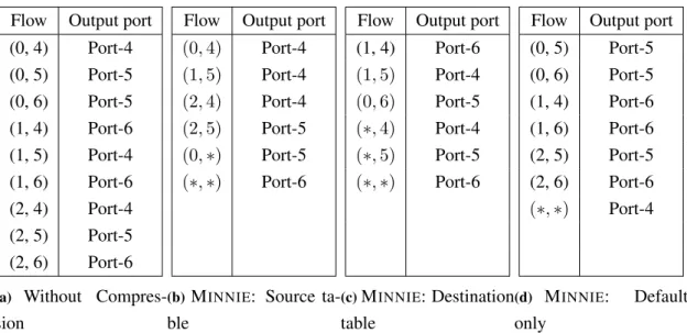
3.1 Examples of routing tables: (a) without compression, (b) compression by the source, (c) compression by the destination, (d) default rule only. Rules’ reading order: from top to bottom. . . 28 3.2 Average number of SDN rules installed in a virtual switch at each level . . . 41 3.3 Average percentage of SDN rules savings at each level . . . 42 3.4 Total number of compressions and packet loss rate. . . 46 3.5 Average percentage of SDN rules savings at each level under high load . . . 51 3.6 Comparison of the behavior of MINNIE for different families of topologies with
around 1000 servers each. For the Fat-Tree topologies, we tweak the number of clients per server to obtain 1024 "servers". . . 61 3.7 Comparison of the maximum number of rules on a switch between XPath and
MINNIE(between servers or ToRs). . . 62
4.1 SDN ports communication matrix Mports as built within the SDN controller for
the flows depicted in Figure 4.8. . . 81 4.2 Bandwidth and time of transmission of 1000 MByte of data from a client to a server. 85 4.3 Maximum number of packets lost. . . 87
5.1 Size of the archived (tar.lzo) image of real-world applications. . . 122 5.2 Maximum number of VNFs that can be configured in a Sink VM with 1 CPU and
Introduction
Contents1.1 Software Defined Networking . . . 2 1.1.1 Mode of Action . . . 2 1.1.2 Main Components . . . 3 1.1.3 Migration from Legacy to SDN Networks . . . 6 1.2 Contributions . . . 7 1.3 Roadmap . . . 8 1.4 List of Publications . . . 10
Networks such as Data Centers (DC) networks and Internet Service Providers (ISP) networks are usually composed of multiple heterogeneous network devices such as switches, routers, fire-walls etc. In DC, the network devices are generally located in the same geographic area and host multiple services. On the other hand, the network devices in ISP networks, also called backbone networks, are geographically dispersed around a country or a continent and host huge amount of traffic. In legacy networks, these network devices should be configured individually by network administrators using Command Line Interface (CLI) to provide the required configuration to apply the defined policy which is very hard to manage, as network policies are getting more complex and are sometimes restrained by the network device provider [BAM09]. In addition to config-uration complexity, the increase in traffic variability and network dynamics pushed towards the need for programmable networks that will allow network administrators to program network devices to allow them to take actions on certain events [NMN+14]. Active networks (AN) were proposed as a first attempt to program the network. AN allow network devices to do complex com-putations based on the received packet’s contents, and then based on the computation result one might change the packet’s contents [TSS+97]. The Software Defined Networking (SDN) inherits from the AN, where SDN networks also perform complex computation on the received packet’s content. However, the computation is done on a centralized entity called the controller and the context has changed where, nowadays, flexibility is not an option anymore as exemplified by the wide industrial support (HP, AWS, etc.) behind SDN.
SDN is a new highly flexible promising network architecture, which overcomes the limits of forwarding mechanisms of legacy IP networks. Indeed, SDN-based networks (or SDN networks, as we will call it in the remaining of this document) might not only use the IP destination address to make forwarding decisions, like legacy IP networks do, but can also use several other information from the MAC, Network and Transport header of packets [The12]. SDN technologies make also a clear separation between the control plane and the data plane where the two planes are physically separated where the forwarding devices only have the data plane and the control plane is moved to a centralized entity, the controller. In SDN, the forwarding devices (or switches) are considered as dummy devices that only follow the forwarding policies dictated by an external programmable entity: the controller, which implements the control plane (Figure 1.1). Thus, there is no more need to have multiple black-box network devices with specific network functions such as switches, routers, firewalls, etc. Moreover, there is no need anymore to run a CLI to configure network devices, and repeat such operations for every concerned device. In SDN networks, any needed change in the forwarding policies is coded only once in the controller, and the latter will propagate the forwarding rules to all the SDN equipments [HPO13].
1.1
Software Defined Networking
As explained before, an SDN network is composed of four basic components: (i) the controller that implements the control plane, (ii) the forwarding devices/switches which feature the data plane, (ii) the southbound interface, e.g. OpenFlow [The12], which is the communication channel between the controller and the forwarding devices and (iv) the northbound interface which allows the controller to communicate with the user-defined networking applications. In this section, we will first describe in general how SDN networks deal with user’s data traffic, and then we will explain in brief SDN network’s main components.
1.1.1 Mode of Action
Pure SDN networks are composed of SDN switches that are connected to the controller (Figure 1.1). When a packet arrives at an SDN switch, see Figure 1.1 step 1, the switch will first check its list of pre-installed forwarding rules (e.g. Rule: incoming packets from port 1 source A to destination B should be sent at port port 2). If the packet header information do not match any previously installed rule, i.e. packet miss, the switch will then forward the packet to the controller using the default SDN rule (step 2). Upon reception of the data packet on the controller, the network applications in the controller will analyze the packet headers and decide the list of actions to be taken when matching packets arrive at the SDN switches (step 3) e.g. modify the packet header information, forward to port B, flood, drop, etc. Afterwards, the controller will transmit this packet back to the switch and implement the actions directly to it (step 4). In addition to that, the controller will transmit a flow_mod event to the switch which contains the list of forwarding rules that need to be installed in the switch (step 5) so that next upcoming matching packets can
Figure 1.1: SDN data packet treatment process.
be treated directly on the the switch without the need to forward them to the controller.
1.1.2 Main Components
1.1.2.1 SDN Forwarding devices
As explained earlier, SDN forwarding devices also called SDN switches do not have any built intelligence that allows them to analyze the packets. When SDN devices are integrated in an SDN network, they first notify the controller of their existence, their basic configuration and state of their components (ports, directly connected links, tunnels etc). These switches then rely on the controller to give them a set of rules to know how to treat incoming packets. These rules, also called forwarding rules, are then saved in the switch physical memory. SDN switches mainly use the TCAM to store the flow. TCAM allows rapid matching of packets as it is able to search all of its entries in parallel [ZHLL06]. However, TCAM memory is both expensive and power hungry [COS], hence most physical switches provide small TCAM memory supporting around a couple of thousands to no more than 25 thousands flows [SCF+12a]. When the TCAM is full, the SDN rules are then placed in the software memory. However, installing rules in software ( that is classical RAM) degrades the performance as packet matching will then require to use the Central Processing Unit (CPU) of the switch which will increase the delay, a.k.a the slow path.
Two types of SDN switches exist: (i) hardware switches such as Pica8 [PIC], HP 5412zl [hp5] etc and (ii) software switches such as OpenvSwitch (OvS) [PPK+15]. Only hardware switches install the forwarding rules (flows) in the TCAM. Software switches such as OvS can however benefit from the memory cache to boost performance. The functionality of the forwarding de-vice, depends on the forwarding rules installed, it can act for example as standard switch, router, firewall, load balancer all together.
1.1.2.2 Southbound Interface
The southbound interface allows the exchange of control messages between the controller and the SDN forwarding devices. This interface dictates the format of the control messages exchanged between the controller and the forwarding devices in the network protocol. Multiple southbound interfaces exist such as OpenFlow [The12], ForCES [DDW+10], and POF [Son13]. ForCES southbound interface requires the presence of the ForCES architectural framework in the legacy networking node, e.g. router. The ForCES architectural framework logically separates the control elements (i.e. operating system) from the forwarding elements (i.e. ASIC) inside the legacy node. In this architecture, the ForCES protocol allows to define logical functions on the control elements. These functions are then sent to the forwarding elements without the need to: (i) insert a centralized controller entity or (ii) change the legacy network architecture. Thus, ForCES requires the control plane to be managed by a third-party firmware and lacks centralization of the control plane. On the other hand, POF southbound interface allows– similarly to OpenFlow– the total physical separation of the control and the data plane which leads to a total change in the legacy network architecture to enable the use of controllers and forwarding devices. However, unlike OpenFlow, POF does not dissect the packet header on the switch to match incoming packets, it rather uses a generic flow instruction set (FIS) generic key that the switch uses to perform packet matching on the forwarding devices.
In our work, we used the OpenFlow SDN architecture which uses the OpenFlow protocol as the southbound interface as it is the most deployed SDN protocol southbound interface [MOS]. Multiple OpenFlow protocol versions exist especially (v1.0, 1.3, 1.5). During this thesis, we used the most stable releases of OpenFlow at the time (v1.0 and v1.3). In OpenFlow, an SDN forwarding rule- also called a flow entry- is composed of three parts:
1. Match fields: packet header values to match the incoming packets in addition to the ingress port- to match any value of a specific field a wildcard is used.
2. Actions: set of instructions to apply to the matching packet such as forward to port B, flood, drop, send to controller or modify packet headers.
3. Counters: used to collect statistics of packet and byte count match for each flow in addition to the idle and hard timers information.
All OpenFlow protocol versions use the same structure of SDN rules, with some action and match-ing field additions in each version. The basic flow rule in v1.0 matched 12 packet header fields. This increased to 15 fields in v1.3. The usage of multiple field matching instead of destination based matching in the switches allows thus to unite multiple legacy network device functionali-ties in a single rule. However, the forwarding rule complexity comes at the price of increase in memory space used per rule.
Figure 1.2: SDN network structure. [KREV+15]
1.1.2.3 Controller Server
In SDN, the controller server is responsible for managing the control plane of all the network. The controller server is composed of (Figure 1.2):
• Network Operating System (NOS) • Northbound interface
• Network applications
The SDN controller runs on the NOS, where the NOS is the main software platform1that runs on
any-purpose server and allows the access to the server resources, such as the network interface, and basic services such as input/output services. The NOS allows the applications on the controller server to communicate with the SDN network devices, and creates the global topology view of the network. The NOS is also able to monitor the state (e.g. connected or disconnected) of all the network forwarding elements regularly. The NOS, then, informs the network applications of the network states using the northbound interface such as the REST API. Then, the network applica-tions manage and implement policies in the network devices using the northbound interface.
Based on the network configuration requirements and specific needs, the administrator can program new network applications (new network functionalities) in standard programming lan-guages such as Java, C++ or Python. This gives the administrator full control over the network topology and allows the infrastructure to be reactive to network and traffic dynamics.
1
Two types of SDN controllers exist:
• Centralized controller • Distributed controller
The centralized controller provides a centralized global view of the network which allows online reactivity to spurious changes in network states and simplifies the development of sophisticated functions. These controllers are usually designed to handle small to medium-sized datacenters and enterprise networks flow throughput. However, the centralized controllers fail to handle large-networks throughput. Moreover, the centralization of the control plane in a single node reduces network resilience as the centralized controller represents a single point of failure in the network. Multiple centralized SDN controllers exist such as POX [POX15], NOX [Int12], Ryu [Ryu17], Beacon [Eri13] and Floodlight [Iza15]. In 2013, more than 30 different OpenFlow controller existed that were created by different vendors or research groups [SZZ+13]. These controllers use different programming languages and different runtime multi-threading techniques. The POX controller is mainly used for prototyping [SZZ+13]. The NOX controller is not supported any-more. As for the remaining most known controllers (e.g. Ryu, Beacon and Floodlight), the study in [SZZ+13] shows that Beacon has the best performance, i.e. it features the highest throughput and lowest latency. Thus, in this thesis, we used the Beacon controller. However, when the Beacon controller was not maintained anymore we used Floodlight v2.0 which is a fork of Beacon.
A distributed controller can be either a physically distributed set of controllers, or a central-ized cluster of controller nodes. A distributed controller provides fault tolerance, but requires an additional overhead to maintain the network state consistent across all the controllers. Hence, when the network state changes there will always be an inconsistency period of time. Multiple dis-tributed controllers exist, e.g. OpenDaylight [Opeb] and ONOS [Ono]. Both OpenDaylight and ONOS provide similar functionalities with similarities in performance. However, while ONOS focuses more on meeting the needs of service providers, OpenDayLight focuses on providing all of the detailed network functions that one needs to be able to integrate any functionality required. OpenDaylight is thus said to be the "Linux of networking " [Lin15].
1.1.3 Migration from Legacy to SDN Networks
Since migrating legacy networks to SDN networks comes at a high cost and management complex-ity, different scenarios may be envisioned [VVB14]. The most realistic one is using progressive migration, where the administrators replace legacy devices by SDN devices incrementally i.e. en-abling hybrid networks. In hybrid networks, SDN and legacy devices coexist and interact with each other. Nowadays, SDN hybrid devices exist, such as HP5412zl, where a switch device can be configured to have some ports in SDN mode and others in legacy mode. Moreover, SDN hybrid devices can act either as legacy devices by communicating using legacy routing protocols or as pure SDN devices. Hence, the migration from legacy to pure SDN network is cost efficient.
Multiple big companies have started integrating SDN in their networks, e.g. Google has de-ployed software defined network to interconnect its datacenters [JKM+13]. Based on [JKM+13] the integration of SDN in their production network helped improve operational efficiency and reduce network cost.
Several types of hybrid topologies exist such as topology-based, service-based, class-based and integrated hybrid SDN topologies [KREV+15]. In topology-based hybrid SDN networks, the network is divided into different zones, and in each zone all the nodes are either legacy nodes or SDN nodes. In service-based hybrid SDN networks, some network services are provided by legacy devices (e.g. forwarding) while other services (e.g. traffic shaping) is provided by SDN. In class-based hybrid SDN nodes, the traffic is separated into classes, where depending on the class of the traffic and the network administrator configuration, the traffic would be managed either by SDN or by legacy protocols. As for the last type, i.e. integrated hybrid SDN networks, SDN is responsible to provide all the required networking services and then it uses the legacy protocol as an interface to the forwarding base (e.g. OSPF). Several controllers such as OpenDaylight [Opeb] and OpenContrail [Opea] integrate non-SDN technologies such as BGP, SNMP and NETCONF2 [EBBS11] to enable hybrid networks.
In this thesis, in addition to using pure SDN networks, we also used a mix of topology based and integrated based hybrid SDN networks. We constructed hybrid SDN networks that: (i) contain a mixture of SDN and legacy nodes (topology-based) and (ii) use the legacy routing protocols to communicate with the legacy devices and with the forwarding information base (integrated hybrid SDN).
1.2
Contributions
The creation of SDN which allows the centralization of the control plane, global network view and network programmability, gives the opportunity to create new services that allow to enhance legacy network performance and bypass their limitations and restrictions. However, Software Defined Networking is a new evolving network architecture that is still in its infancy. To enable its maturity and full SDN networks deployment, multiple research topics including switch and controllers design, scalability, and resiliency are still under study [KREV+15].
At the beginning of this thesis, we tackled one of the basic problems that SDN devices have, that prevents SDN network’s scalability while maintaining the same level of network performance, which is namely their TCAM limited size [RHC+15, RHC+17]. Then, we aimed at using SDN in order to enhance current network flow performance [RLPUK15, MR17] and decrease the net-work’s energy consumption [HRG+17, DLP17]. In collaboration with the COATI team [COA] at INRIA and with my colleagues in SigNet team [SIG], we developed the following solutions:
• In collaboration with the COATI team, we addressed the problem of limited hardware
mem-2
ory (TCAM) used by the hardware SDN forwarding devices (Chapter 3). Their small size limits the number of SDN flow rules that can be installed in the hardware memory as SDN rules are complex and long. Thus, when the hardware memory is full, new rules will be installed in software which highly degrades the flow performance as we will see in Section 3.2. To allow network scalability while optimizing the usage of the TCAM memory, we cre-ated a solution called MINNIE that dynamically compresses the routing rules in an SDN node to maximize the number of flows that can use the TCAM memory.
• We leveraged the benefits of the centralized control plane at the SDN controller, and its capability to have a general view of the topology to enhance the flow performance in the network. We proposed two solutions:
– A prototype that provides dynamic scheduling in the datacenter based on the flow and port statistics feedback at the controller. This approach is innovative as it tries to extend SDN to alter the data plane of the switch (here the scheduling policy). Unfor-tunately, this solution was effective only on small-size datacenters.
– A solution named PRoPHYS that allows to provision network link failure or link dis-ruption in hybrid ISP networks. This solution monitors the flow paths in the network, and leverages the received information to estimate whether a network failure has oc-curred. Then, after detecting a possible failure, PRoPHYS reroutes the traffic that uses the assumed down network segment to minimize the amount of traffic that could be lost in case of network failures.
• Then we focused on the energy problem in datacenters and SDN hybrid ISP networks. – To enhance energy efficiency in ISP networks we created a solution called SENAtoR
(in collaboration with the COATI team) that inserts SDN nodes in legacy networks to avoid packet loss when network devices are turned off to save energy.
– To tackle the energy problem in the datacenter in the SigNet team, we started working on the SEaMLESS project which helps decrease the energy consumption of enterprise cloud networks. SEaMLESS migrates an idle VM service (e.g. idle Web server) to a lightweight virtual network function (VNF) service. This enables to turn off idle virtual machines (VMs) while maintaining the connectivity to the network services provided by the virtual machine (VM).
1.3
Roadmap
In this chapter, we listed the added benefits of SDN over legacy networks, and defined the main concept and components of SDN networks and their mode of actions. We then introduced the concept of hybrid networks and their importance in the migration from legacy to SDN networks. Finally, we summarized in brief the main problems that we tackled during this thesis and our main
contributions. We provide below a brief outline of the rest of the manuscript.
Chapter 2 introduces the main challenging research topics of SDN networks. It then states in general the major contributions that the research community have already provided to enhance SDN networks.
Chapter 3 introduces our solution called MINNIE that was developed in collaboration with the COATI team. In this chapter, we first define the problem that MINNIE solves and then we explain the theoretical basis of this solution. Afterwards, we provide experimental testing results to validate the efficiency of this solution and its impact on the network traffic and network devices functionality. Then, we provide our numerical evaluation results that prove the scalability of this solution. At last, we sum up our findings along with a discussion of the possible extensions of this work, its adaptability to network traffic, and its impact on multiple domain such as security.
In chapter 4, we introduce our SDN solutions to manipulate the data plane of SDN switches to improve the resilience and performance of SDN networks. Both solutions leverage the centrality of the control plane at the controller, capability to maintain a general network topology view at the controller and capability to prompt the switches for statistics. In the first section, we describe our coarse grained scheduling solution for datacenter networks that aims at decreasing the flow completion time of small flows. We start by explaining the basic idea of our solution, then we provide some basic experimental results that show the efficiency and the limitation of our solution. Then, in the second part of this chapter, we extend our coarse grained scheduling solution and we develop a new solution called PRoPHYS for hybrid ISP networks that aims at enhancing flow resilience against unexpected failures in a hybrid network. We first describe the technique and the algorithm used to detect failures across non-SDN network segments in a hybrid network. Then, we provide our results that show the efficiency, performance and scalability of our solution. At the end of this chapter, we conclude with a summary of the results as well as the limitations and possible extensions of the solutions presented in this chapter.
In the last technical chapter of this thesis, Chapter 5, we tackle the energy efficiency problem in data center and ISP networks. We introduce our solution called SENAtoR that was developed in collaboration with the COATI team in INRIA and describe in brief the recently started project in SigNet team called SEaMLESS. For the case of SENAtoR, we describe the heuristic that computes the set of devices to turn off (nodes or links), and the basic technologies that this solution uses in order to keep near zero packet loss rate even when sudden traffic peaks occur. Then, we provide some testing results that prove the efficiency and practicality of our energy efficient solution SEN-AtoR which allows almost zero packet loss. Afterwards, in the second part of this chapter, we describe SEaMLESS where the SigNet team proposes to save energy by turning off idle VMs by keeping their service connectivity up and running by migrating the front end of the service from its hosting VM to a VNF. We describe first how does the migration mechanism works when mi-grating from VM to VNF and vice versa while preserving network state and connectivity. Then, we provide some basic testing results that show the efficiency of SEaMLESS and its impact on user’s traffic and energy consumption.
We conclude this document in Chapter 6, where we sum up all of our contributions and describe in details the future work that can take place to enhance our work and extend its imple-mentation use cases.
1.4
List of Publications
• Journal– Rifai, M., Huin, N., Caillouet, C., Giroire, F., Moulierac, J., Pacheco, D. L., & Urvoy-Keller, G. (2017). Minnie: An SDN world with few compressed forwarding rules. Computer Networks, 121, 185-207.
• International Conferences
– N.Huin, M.Rifai, F.Giroire, D.Lopez Pacheco, G.Urvoy-Keller, J.Moulierac , "Bring-ing Energy Aware Rout"Bring-ing closer to Reality with SDN Hybrid Networks", IEEE Globe-com 2017.
– M.Rifai, N.Huin, C.Caillouet, F.Giroire, D.Lopez, J.Moulierac ,G.Urvoy-Keller "Too many SDN rules? Compress them with Minnie", IEEE Globecom 2015.
• National Conferences
– Myriana Rifai, Nicolas Huin, Christelle Caillouet, Frédéric Giroire, Joanna Moulierac, et al.. MINNIE : enfin un monde SDN sans (trop de) règles. ALGOTEL 2016 - 18èmes Rencontres Francophones sur les Aspects Algorithmiques des Télécommunications, May 2016, Bayonne, France.
• Poster
– D. Lopez Pacheco, Q. Jacquemart, M. Rifai, A. Segalini, M. Dione, G. Urvoy-Keller "SEaMLESS: a lightweight SErvice Migration cLoud architecture for Energy Saving capabilitieS", ACM SoCC 2017.
– Myriana Rifai, Dino Lopez, Guillaume Urvoy-Keller,"Coarse-grained Scheduling with Software-Defined Networking Switches", ACM Sigcomm 2015.
• Research Report
– Myriana Rifai, Dino Lopez, Quentin Jacquemart, Guillaume Urvoy-Keller "PRoPHYS: Providing Resilient Path in Hybrid Software Defined Networks".
State of the Art
Contents2.1 Attempts to Overcome SDN Challenges . . . 12 2.1.1 Control Plane Scalability . . . 13 2.1.2 Resilience . . . 14 2.1.3 Multiple Switch Designs Interactivity . . . 15 2.1.4 Flow Table Capacity . . . 15 2.1.5 Switch Performance . . . 16 2.2 Attempts to Enhance Network Performance using SDN . . . 17 2.2.1 SDN in hybrid networks . . . 17 2.2.2 Traffic Engineering and Energy Efficiency . . . 18 2.2.3 Resilience . . . 19 2.2.4 Network Virtualization and Management . . . 20 2.3 Conclusion . . . 20
During the last years, Software Defined Networking has been developing rapidly and a lot of researchers have been working on migrating legacy networks to full SDN to benefit from network programmability, control plane centrality, and global network view that SDN technology features (Figure 2.1). However, the full migration to full SDN is blocked by the centrality of the controller which features a single point of failure, lack of standardization of SDN protocols and switch design, and the limited scalability and performance of SDN controllers and hardware switches [KREV+15]. However, even-though SDN is still under development, multiple research domains benefited already from its development where SDN is being deployed in current networks such as Facebook [dep15] and Google B4 network [JKM+13]. Legacy networks, traffic engineering, energy efficiency, network virtualization and network management domains have all leveraged the centrality of the control plane, programmability and the global network view of the whole topology at the SDN controller.
Figure 2.1: SDN main research topics discussed in this thesis.
In the first section of this chapter, we present a non-exhaustive list of the main solutions that address the main challenges of SDN. Then, in the second section, we provide a list of solutions that solve existing problems or limitations in current SDN or legacy networks and enhance the overall network performance and programmability.
2.1
Attempts to Overcome SDN Challenges
The basic idea behind Software Defined Networking is the physical separation of the control plane from the data plane and the centralization of the control plane at the controller. Though the central-ization of the control plane at the controller provides a global view of the network, and provides administrators with the capability to dynamically control and program the network, it is accompa-nied by multiple challenges. First, the separation of the control plane from the data plane would require a communication channel between both layers to transmit control messages. This commu-nication channel becomes the bottleneck when a large number of control messages are transmitted between the controller and the SDN switches. Second, the fact that the control plane is totally sep-arated from the data plane decreases network resilience and fault tolerance. In SDN, the network undergoes the risk of loosing data when a network failure prevents the communication between the data plane and the control plane. Moreover, the centralization of the control plane might constitute a single point of failure.
In addition to the two main challenges stated above, recent studies proved that SDN switches (data plane) have pointed out other potential weaknesses of SDN. Due to the lack of standardiza-tion of SDN switch design and southbound interface, multiple SDN switches exist each featuring its own set of actions and communication protocol. Some switches use OpenFlow protocol (v1.0 or v1.3 till v1.5 etc), while others use POF. Hence, a new mechanism should be elaborated to either enable the communication between all the switches or standardize the switch design and southbound interface. Moreover, as we will see in this thesis, SDN devices have limited flow table capacity and limited network performance which prevents network scalability. In this section, we detail the challenges stated above and we discuss some works that were designed to address them.
2.1.1 Control Plane Scalability
As stated before, the separation of the control plane from the data plane hinders the scalability of the network as the communication channel between the controller and the data plane could become the bottleneck. The centralized controller could also be the bottleneck as all the SDN switches in the network will ask the centralized controller for decisions to analyze and route the traffic in the network, increasing the control traffic, the processing load on the controller and the flow installation and processing delays [TGG+12]. The data plane (SDN switch) could also become the bottleneck for the same reasons stated above. The lack of scalability in any of these three components (SDN switch, controller and the channel between them) will hinder the scalability of the whole network increasing the flow delay and possibly causing flow loss degrading the Quality of Service (QoS).
To enhance control plane scalability researchers attempted to enhance the performance of the controllers by: (i) building distributed controllers [Ono, Opeb, KCG+10, DHM+14, KCGJ14], (ii) dynamically deploying controllers based on network traffic demand (elastic control plane) [BRC+13, TG10] and (iii) enhancing the performance of a single controller [Eri13, NCC10, TGG+12] by using the new developments in parallelism and multi-threading. Distributed con-trollers such as ONOS and OpenDaylight [Ono, Opeb] distribute the control plane on a group of controllers which allows the controllers to manage bursts of network traffic. ElastiCon [DHM+14] is also a distributed controller with an additional elasticity feature that supports the addition and deletion of controllers based on traffic demands. However, the drawback of distributed controllers is their need to exchange information among each other to preserve a consistent view of the net-work topology which increases the control traffic, could increase the processing delay and can result in network inconsistencies. On the other hand, a centralized controller manages the whole network topology and will thus always have a global centralized view of the network. Thus in [BRC+13], the authors suggested to deploy centralized controllers dynamically in the network based on traffic demand to preserve scalability. Hyperflow [TG10], provides scalability while maintaining a centralized control plane. It features a logically centralized but physically distributed controller which allows to centralize decision procedures but distributes SDN switch events among the control nodes. Nonetheless, the centralization of the control plane could lead to a single point of failure.
In addition to enhancing the performance and scalability of the controller, some researchers enhanced the scalability of the control plane channel (channel between the controller and the SDN switches) [CMT+11, YRFW10, HSM12]. In [CMT+11], the authors propose DevoFlow which modifies the OpenFlow model by allowing only significant flows to contact the controller and uses wildcards aggressively in the flow table to decrease the number of control messages transfered between the controller and the switch. Difane [YRFW10], similarly to DevoFlow, tends to decrease the number of flows– that require the controller intervention– to be installed by using intermediate switches in which the controller stores some necessary rules to be used by the end switches. Though these solutions can decrease the load on the control channel, they can not be
deployed in networks where complex policies are implemented or flow rules are created due to network dynamics. In addition to decreasing the number of events arriving at the controller, some researchers studied the placement of the controllers in the network to decrease the traffic load on the links connecting the switches to the controllers [HSM12, JCPG14] to avoid traffic loss. Unfortunately, so far, these placement solutions can not decrease the control load on the links, maintain the minimum delay between the switch and the controller, and be resilient to link failures all together.
Finally, to enhance the scalability of SDN switches, some researchers aimed at decreasing the processing delay on SDN switches by migrating the counters from the hardware memory Application-Specific Integrated Circuit (ASIC) to the software memory such as Software-Defined Counters (SDC) [MC12], in addition to enhancing the SDN switch performance (see Section 2.1.5) and increasing the switch flow table size (see Section 2.1.4).
2.1.2 Resilience
The centralization of the control plane at the controller degrades the resilience of SDN networks. In such networks, the controller becomes a single point of failure. The loss of connectivity be-tween the controller and the SDN devices would lead to the loss of network control, and thus data traffic could be lost. Multiple researchers tried to enhance the resiliency of the control plane (i.e. the controller) [BBRF14] by trying to build distributed controllers such that if one of the controllers fails the remaining controllers can take over its nodes [Ono, Opeb]. But, as stated before these controllers need to constantly exchange network topology information and may re-sult in inconsistent views of the network. In addition to building a fault tolerant controller, some researchers aimed at studying the placement of the controller taking into consideration the fault tolerance ratio and probability of link failure of the links connecting the data plane to the control plane [GB13, HHG+13, HWG+13, LGZ+15]. However, as stated before, to our knowledge there is no placement algorithm that can provide scalability, resilience and performance altogether.
Others studied additional architectures or methodologies that enable the switch itself to over-come failures without disrupting the controller state machines [KZFR15, BBRF14]. In [KZFR15, BBRF14], the authors introduce a platform where the switches and the controller maintain a state machine (stored in a shared database or independently) to know whether the data traffic has been treated correctly. In case of failure, the switch can manage the data traffic using the state ma-chine database information and then informs the controller once the connection is re-established. Notwithstanding, storing the state machine in a shared database would increase the controller analysis delay, which degrades the controller’s performance.
Moreover, to maintain network resilience, the authors of [WWW+14], suggested a simplistic solution that pre-installs backup routes in the switches. These backup routes are then used quickly as "fast-fail-over" actions where the switch monitors its port and upon the failure of one port, the switch uses the set of backup rules related to the port failure. However, these solutions require the
installation of additional forwarding rules on the switch decreasing the available memory space for main forwarding rules.
2.1.3 Multiple Switch Designs Interactivity
After the development of SDN architecture, many researchers and industrial companies (e.g. HP, Juniper, Brocode) developed SDN switches and southbound interfaces. However, the lack of standardization, lead to the creation of diverse SDN switches, each one having a unique flow table structure, set of actions to be applied to incoming traffic, and different versions of supported south-bound interfaces, such as POF and OpenFlow v1.0, v1.3, etc. The diversity of SDN switches and southbound interface design increased the complexity of managing the communication between the controller and the SDN switch. To accommodate the heterogeneity of the data plane devices and the heterogeneity of the southbound interface multiple solutions such as NOSIX, tinyNBI, and libfluid [YWR14, CSS14, VRV14] arose.
Both libfluid [VRV14] and tinyNBI [CSS14] attempted to create an API capable of supporting the heterogeneity of OpenFlow. TinyNBI API supports the heterogeneity of all OpenFlow versions between 1.0 and 1.4 while libfluid API supports only versions 1.0 and 1.3. NOSIX [YWR14] on the other hand, was developed as an API that supports the heterogeneity of the SDN switch flow table features. NOSIX creates a single format of virtual flow table on all types of SDN switches, then it translates this virtual table to the actual switch forwarding table. Though NOSIX, tinyNBI, and libfluid were provided to allow the existence of multiple types of SDN protocols and SDN switch designs in the network, they still do not cover the full diversity of SDN devices and SDN protocols and they add processing delay to decrypt the messages and encode them in the correct protocol version or forwarding table design.
Finally in [HYG+15], the authors propose a new all programmable SDN dataplane switch, called ONetSwitch, that can cope with all SDN platforms while maintaining a high performance, flexibility, small size and low power consumption. ONetSwitch can be both reprogrammed and hardware restructured to cope with the different physical requirements and inner functionalities required so that it can cope with all current SDN protocols. Nonetheless, this switch is still a prototype and have not been fully implemented or tested in real networks.
2.1.4 Flow Table Capacity
Current SDN hardware switches use TCAM hardware memory to store their forwarding tables. Though this memory is both expensive, small, and power hungry [COS], it is used in current SDN network devices due to its very high lookup speed (around 133MHz [KB13b], i.e. 133 million lookups per second). Thus, a lot of research has been conducted to maximize the number of SDN rules in the TCAM memory. Some researchers, among many others, aimed at decreasing the total number of rules such as [RSV87, ACJ+07, MLT10, MLT12] while others tried to decrease the size