HAL Id: inria-00350648
https://hal.inria.fr/inria-00350648
Submitted on 7 Jan 2009
HAL is a multi-disciplinary open access
archive for the deposit and dissemination of
sci-entific research documents, whether they are
pub-lished or not. The documents may come from
teaching and research institutions in France or
abroad, or from public or private research centers.
L’archive ouverte pluridisciplinaire HAL, est
destinée au dépôt et à la diffusion de documents
scientifiques de niveau recherche, publiés ou non,
émanant des établissements d’enseignement et de
recherche français ou étrangers, des laboratoires
publics ou privés.
severely handicapped people - A one click approach.
C. Dune, Cédric Leroux, E. Marchand
To cite this version:
C. Dune, Cédric Leroux, E. Marchand. Intuitive human interactive with an arm robot for severely
handicapped people - A one click approach..
IEEE Int.
Conf.
on Rehabilitation Robotics,
Intuitive human interaction with an arm robot for severely
handicapped people - A One Click Approach
Claire Dune
1,2, Christophe Leroux
2, Eric Marchand
1 Abstract— Assistance to disabled people is still a domain inwhich a lot of progress needs to be done. The more severe the handicap is, more complex are the devices, implying increased efforts to simplify the interactions between man and these devices. In this document we propose a solution to reduce the interaction between a user and a robotic arm. The system is equipped with two cameras. One is fixed on the top of the wheelchair (eye-to-hand) and the other one is mounted on the end effector of the robotic arm (eye-in-hand). The two cameras cooperate to reduce the grasping task to ”one click”. The method is generic, it does not require marks on the object, geometrical model or the database. It thus provides a tool applicable to any kind of graspable object. The paper first gives an overview of the existing grasping tools for disabled people and proposes a novel approach toward an intuitive human machine interaction.
I. INTRODUCTION
People often wish computers would behave according to what they really have in mind. Technological tools (phones, computers, multimedia, home domain, mobile devices gateways or games) taking more and more importance, day after day, many people feel they spend far too much time in making these things work rather than benefiting from their services. These problems are familiar to valid people. They can frequently lead to a rejection of technology.
Current works on pervasive or autonomic
computing [44], [32] aim at hiding these technological aspects and tool management problems from the end user. Furthermore in robotics for many years now, efforts have been made to simplify users’ tasks. The existing solutions include the use of force or haptic feedback as well as three dimensional graphic supervision [35]. This assistance however, remains non-intuitive since it always needs great attention from the operator. In this paper we present our work and results conducted on an intuitive human machine interface and aiming at hiding the technological aspects of the devices involved.
The application we study is the grasping of unknown and non marked objects with a robotic arm controlled by quadriplegic people. Severely disabled people could be seen as an extreme case in the study of the relation between a human and a machine - If a system is suitable for use by people suffering from a handicap, this system is
1INRIA, IRISA, Lagadic Project, F-35000 Rennes, France 2CEA List, F-92265 Fontenay Aux Roses, France
This work has been done at IRISA-INRIA Rennes in collaboration with CEA List. It was also supported by CEA and by Brittany County Council under contribution to student grant.
Fig. 1. Survey on the interest of disabled people for grasping and releasing objects [3]
straightforward for a valid person to use. We can say this system has been ”designed for all”.
Section II presents a state of the art of object grasping for disabled people. This section also introduces the main categories of robotic assistance to disabled people and carries on with a description of the main human machine interface principles proposed to a user to interact with a robotics grasping tool. Section III is dedicated to the method we propose, which reduces the effort of the user to trigger some robotic action to minimum. Section IV presents the perspectives and next stages of our research.
II. OVERVIEW OF THE STATE OF THE ART Service robotics is a fast growing field. One of its application is the development of robotic assistants for elderly or disabled people. The World Health Organization [40] states that several actions like carrying, grabbing, picking up and moving objects may be achieved by robots. According to [3], a survey investigating disable people’s opinion about robot aids, almost 50% of the subjects feel that a robotic arm would have a positive effect on the level of care they would need. Only 4.5% feel negative about this effect. Furthermore, 86% of the subjects feel that they would be able to achieve new things in their life and especially 66% think that the possibility of grasping and releasing objects is important to them (see fig (1)).
Besides, since the late 1960’s one of the main objectives of rehabilitation robotics has been to help disabled people to recover some manipulation capabilities in their everyday-life [23]. The Rancho ”Golden” arm, developed at Rancho Los Amigos Hospital in Downey, California in 1969 was
Fig. 2. four types of robots for disabled people : a) workstationMAS
-TER[11] ; b) ISAC stand alone Robot [31]; c) Victoria wheelchair mounted
robot [9] d) Care-O-Bot mobile manipulator [21]
the first successful rehabilitation robot manipulator[1].
A. Four main types of rehabilitation robots
Surveys of the different rehabilitation robotic projects, show four main developmental concepts [30], [24], [29] (see Fig (2)):
1) Static robots that operate in a structured environment (workstation) ;
2) Stand alone manipulators ;
3) Wheelchair-mounted robotic systems ; 4) Mobile manipulators following the person.
1) Workstations: Workstations were the first robots
designed for disabled people. Their aim was to give disabled people more autonomy in their daily work. Basically, a workstation is made of a desk and some shelves where a robotic manipulator is fixed. No sensor is used. The arm is programmed to hit some parts of the desk or shelves to get some specific devices, such as draft paper, phone, printer, book whose position is perfectly known. All the objects have to be installed and organized at the dedicated places by a valid person. The projects DeVAR [48], ProVar [49], RAID [28] and Master [11] are some examples of desks equipped with a robotic arm. Another type of workstations are low-cost workstations dedicated to self feeding tasks. They consist of a light weight robotic arm mounted on a special plate that is either
put on a table or mounted on a stand. RAIL [47], Handy
I [46] and MySpoon [27], [45] are some systems of this type.
Workstations offer good mechanical stability but they suffer from a lack of reaction with respect to changes in its environment that is expected from assistant robots : any error between the current and the expected position of an object results in the failure in its grasping task. Therefore, the idea of using sensor for environmental perception is attractive.
2) Stand alone manipulators: The second type of robotic
system is stand alone. It is made of a robotic arm fixed on a desk or a stand and equipped with sensors. The positions of the objects to grasp is not known and the sensors are used to get some information about the robot’s environment. The Tou robot [12] and the ISAC robot [30] are two examples of such systems. A drawback of such systems is that they can’t handle objects that are far from their fixtures point, which a mobile robot could grasp.
3) Wheelchair mounted manipulators: Another type of
rehabilitation robot is a wheelchair fixed with light weight manipulators. It allows disabled people to feed themselves and reach objects on the floor, on a table or above their head. A survey on this type of robotic systems is given in [2].
The current market leader of this type is the MANUS [17],
[33]. The manus arm can be controlled by devices adapted to the handicap : smart ball, breath control, eye movement based control, panel, joystick, voice, etc. It is used in several research projects such as FRIEND [50], AVISO [34], [35] and VICTORIA [9]. Their purpose is to command the arm by using information given by vision sensors, in addition VICTORIA [9] sets up a mimic recognition interface and a touch screen and FRIEND [50] presents a voice controller and a special tray that is covered with force sensor. Another wheelchair arm currently available is the Raptor arm [38] that can currently only be controlled by a keypad and a secondary joystick.
These systems are fixed on the wheelchair, the working area is thus limited to the close neighborhood of the wheelchair.
4) Mobile robots: The fourth type of rehabilitation
systems consists of a mobile manipulator following the user’s wheelchair. WALKY [39], MOVAID [14], ARPH [25], HERMES [8], KARES II [7], CARE-O-BOT [21] are examples of such systems. These robots bring in new advantages: the ability to move independently from the wheelchair, they can move from one room to another and fetch and carry objects and they can be shared by more than one person, whereas wheelchair-borne robots are personal.
5) Mats system: Apart from this classification stands the
Mats system [4]. This system is made of a single arm that can dock into a table or into a wall. Thus it can be seen as a workstation as well as a wheelchair mounted device, that’s why we will consider it belongs to wheelchair mounted arm. Any robotic assistant is controlled by the user through a specific interface to fetch and carry objects. How to
designed such an interface ? How to share the tasks between the robot and the user for the system to be the more secure and the less tiring ?
B. Existing Human Machine Interface (HMI)
According to some surveys [10], [30], [24], [29] disabled people expect robots to give them a better autonomy in their every-day life. Moreover, they do care for the quality of the tools provided by rehabilitation robotics. They ask for safe, not complicated and reliable devices that do not re-quire painstaking trainings.Another characteristic that would clearly facilitate the generalization of robotic assistance is obviously its price. Because of their low price and ease
of use, Hand 1 and MANUS arm were two commercial
successes [24], [43]. Providing disabled people with both intuitive and inexpensive grasping tools is becoming one of the main issues in the rehabilitation robotic field.
All robots above-mentioned are equipped with several control modes: manual, automatic and shared. In [10], it is shown that even though people find automatic and share modes interesting, 80% judge the manual mode as necessary on security and autonomy grounds but in practice too slow and too complex. What should be controlled by the robot for the user to feel secure? Most of the time, reflex-like part is given to the robot and high level tasks, such as decision making, are made by the driver.
In the case of a grasping task, three phases may be distinguished : the designation of the object to seize, the approach toward the object and the grasping of the object. This paper addresses the two first steps.
1) Designation of the object to seize: During the first
phase, control can be shared between the man and the machine or left manually driven by the user. On the one hand, the user has to launch the robot action. On the other hand the user needs a feedback about the robot system state to validate or discard the robot interpretation. A wide spread way to communicate is the use of a graphical interface displaying on a monitor the view of cameras mounted on the arm or the wheelchair [21], [34], [50], [9], [25]. To select the object to grasp, the user may use a commercial devices adapted to his handicap [10], such as touch screens [9], [21] or higher level tools such as mimic recognition [9] or speech recognition [50], [11], [21].
Then four approaches for objects detection may be distin-guished:
1) The objects are marked using visual marks or RFID [9];
2) The objects appearance are known and stored in a database;
3) Some geometrical models are known and stored in a database;
4) The objects are not known a priori by the system. In the case of known objects (1, 2) users may exploit a high level controller such as speech recognition (”Give me the orange juice”). In the one hand, if the system has to
Fig. 3. The AVISOsystem consists of a MANUSarm [17], [33] mounted on a wheelchair, a stereo vision system fixed on the end effector of the arm, a graphical interface displayed on a monitor, any device adapted to the user’s handicap (speech recognition, head movement, breath controller, joystick, etc. )
grasp a new object that has never been seen, the methods based on object database are less efficient than methods based on geometrical model and generic objects. In the other hand, the higher flexibility of other methods, due to the lower knowledge imposed on considered objects, requires nevertheless a higher implication of the user. He may give the robot some additional information about the object location. For example, if the sensors are cameras, the user may select an area where the object is in the camera’s view [34], [9]. Then the question is how to select efficiency and accurately an object in a view ? In [16] a first step towards intuitive object selection was proposed.
2) The approach toward the object: The second phase
deals with the arm approach toward the object. This is the step during which the arm reach a pose that allow him to make the final grasp. It goes from its initial pose to this final pose avoiding obstacles, occlusions, positioning the gripper etc. This step could be done in an automatic mode but most of the time it is a shared control [34], [25]. In the ARPH project [25], manual modes are used either to avoid obstacles or to correct the gripper position. At start, the arm’s position is a random, thus the object is not necessarily in the field of view of the eye-in-hand camera. A drawback of most of the methods using vision sensor is that the object to grasp must be in the cameras’ fields of view. So, the object has to be brought in the cameras’ field of view before performing the approach. In the AVISO project [34] the user has to move manually the arm in order to bring the object into the field of view of the camera that is fixed on the gripper. Although it could take several user actions and it is quite tiring for the driver, this step is necessary to grasp an object. This paper proposes a solution to bring the object in the mobile view autonomously. The user launches the grasping only by clicking once in a wide view of the scene.
The solution presented in this paper is using a MANUS
object fixed frame eye-to-hand camera camera eye-in-hand
Fig. 4. Eye-in-hand/eye-to-hand system reference frames
the end effector of the arm (eye-in-hand) and one camera is mounted on the top of the wheelchair (eye-to-hand). It aims at minimizing the user control of the robot to ”One Click” on the view of the eye-to-hand camera. The ”One Click” project
[16] is based on the AVISOproject [34] (see Fig3). The next
section(III) is dedicated to the autonomous positioning of the gripper for eye-in-hand camera to focus on the object from ”One Click” [16]
III. ONE CLICK METHOD FOR THE ARM APPROACH TOWARD THE OBJECT
In order to make the grasping task easier to control, the approach of the arm toward the object should be performed in an automatic mode. In [16], we have developed a method to focus on the object using only the information provided by the user click. The system is a wheelchair equipped with the
MANUSrobotic arm and two cameras. One camera is called
”eye-to-hand”. It is mounted on the top of the wheelchair and it gives a large view of the scene. The other one is called ”eye-in-hand”. It is fixed on the gripper. The user’s click on the eye-to-hand view launches the grasping. The object is generic and it is assumed to be within the eye-to-hand field of view, whereas it may not be within the eye-in-hand one. The object lies in a complex scene and no assumption is made about the background. The system is supposedly calibrated, i.e. intrinsic and extrinsic camera parameters are known. The objective of [16] is to achieve eye-in-hand/eye-to-hand cooperation with these two cameras (see fig (4)).
Few papers [36], [20], [18] (and to some extent [26]) deal with eye-in-hand/eye-to-hand cooperation. [36], [20], [18] and most of the multi camera systems assume that the interest area is common to every cameras field of view. On the contrary, in the proposed approach, the object of interest is within the field of view of only the eye-to-hand camera. indeed, this assumption is not necessarily true for the eye-in-hand camera since the initial arm pose is assumed to be purely random. Given a point of the object’s surface in the eye-to-hand camera’s image plane and the calibration of the system, the coordinates along x and y axis of the eye-to-hand camera frame are easy to compute. However, no assumption about the object’s depth is made. The basic idea of [16] is to cover the line of view associated to the clicked point
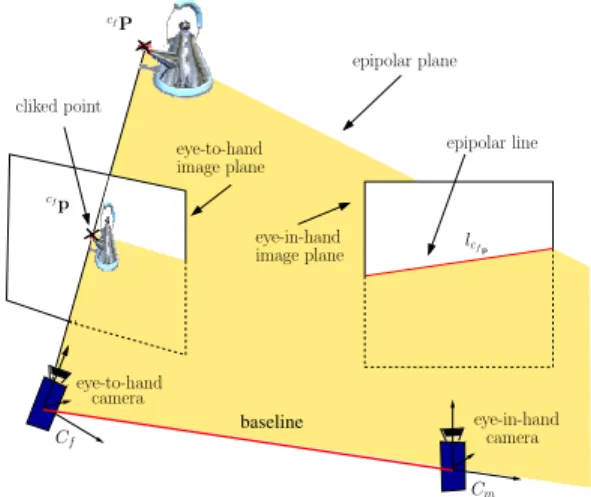
baseline cfP cliked point epipolar plane eye-to-hand image plane eye-in-hand image plane epipolar line lcfp eye-in-hand camera Cm eye-to-hand camera Cf cfp
Fig. 5. Epipolar geometry of the eye-to-hand/eye-in-hand system
where the object is known to be, until sufficient information is gathered to focus on it. The methods involved are epipolar geometry, visual servoing and Bayesian enforcement. they are described in the following of this section.
A. Epipolar geometry
The correspondant of a point in an image is necessarily on a line in an other image, corresponding to the intersection of the epipolar plane and the image plane(see figure (5)). This relation is given by the the epipolar constraint eq. (1) [22], it is well defined by the following equation :
cfpT cfEc
mcmp = 0 (1)
where cfp is the clicked point in the eye-to-hand’s view.
It is the projection of a 3D pointcfP belonging to the object
to grasp andcmp is the projection ofcmP in the eye-in-hand
camera’s image plane.cfEc
m is called the essential matrix and
is defined by:
cfE
cm = [cmtcf]×cmRcf (2)
with cmtc
f and cmRcf are respectively the translation and
rotation matrix between the two camera frames respectively
and [.]×the cross product. The extrinsic and intrinsic camera
parameters are known at each step of the process, allowing to compute the essential matrix and thus the epipolar line at each step of the process.
Therefore, as long as we know the motion between the two cameras (ie. the essential matrix is known), if we ensure that
the epipolar line corresponding tocfp is centered in the
eye-to-hand camera view, then rotating the mobile camera along its normal axis will guaranty the object to get into the eye-in-hand camera’s view at some moments. Such a task may be achieved using a visual servoing scheme [19].
B. Visual Servoing
Epipolar-geometry-based robot control has been studied in the past, mostly for visual homing applications [41], [42], [5], [26]. In [41], [42], the visual servoing is based on
the matching of a desired epipole position and the current computed epipole. In [5], the epipolar lines in both the current and the desired views are computed and aligned. These methods assume that some common visual features are shared in both views so that one can estimate the epipolar geometry. In [26] an initialization step is used to ensure that the object detected by the eye-to-hand camera falls within the eye-in-hand camera’s field of view. Our approach can be seen as an extension of [5] and [26] since the servoing task we propose consists in surfing the epipolar line in order to localize the object of interest.
Visual servoing is a robotic control based on visual
fea-tures extracted from one or several cameras. Let s be the
current visual feature and s∗ be the desired visual feature.
The main task is to regulate the error vector
e1=s − s∗
to zero. The associated interaction matrixL1 of the taske1
links the time variation of the selected visual features to the relative camera/object kinematics screw. It is defined by [19]:
˙
s = Lsv (3) Then, considering the eye-in-hand camera, a control law that regulates e1 is [19]:
v = −λ1cL1+e1+Pz (4)
Where cL1+ denotes the pseudo inverse of an
approxima-tion or a model of L1,λ1 is a positive gain that tunes the
exponential decrease of the task,z is an arbitrary secondary
control vector and P = I − L+
1L1 is a projection operator
that guarantees that the control vectorz has no effect on the
main task e1. Let us introduce a secondary task e2 and its
associated matrixL2. Thenz is set to be:
z = −λ2cL2+e2 (5) By including (5) in (4), the control law computed from the two tasks is:
v = −λ1Lc1+e1−λ2PcL2+e2 (6) With v a 6 dimension vector that is the velocity of the camera that is fixed on the gripper.
In this paper the primary task is a focusing task with regard to the epipolar line while the secondary task allows movements along this line [13], [19]. Indeed, as soon as the visual servoing task ensures that epipolar line is horizontal and centered, the secondary task can be considered to look for the object of interest along the epipolar line.
C. Localization of the object on the epipolar line
The object to grasp is in the neighborhood of the point cfp in the eye-to-hand image (see Fig. 5). So, a view of the object is available and may be used to detect the object in the eye-in-hand image while the eye-in-hand camera is covering
the epipolar line associated with cfp.
A classical object recognition scheme, such as Lowe’s SIFT [37], may be used to match the appearance of the object in eye-to-hand and eye-in-hand images.
Features are extracted and matched all along the movement of the eye-in-hand camera. The main assumption in [16] is that more matched features will be found on the object area than on the rest of the scene.
A Bayesian chaining is used to gather data issued from several views, thus, false matches due to specularities will appear only in some views and there contribution to global depth estimation will decrease using information from other views. The more views taken, the more accurate the estima-tion.
Let A and B be two random values and P a probability density function (we refer to it as pdf), P(A|B) is a condi-tional probability density function of A knowing B. Bayes formula is the following [6], [15]:
P(B|A) = P(B)P(A|B)P(A) (7)
P(B|A) is the a posteriori probability (we refer to it as
posterior). It is the current probability of B knowing A. P(B) is the a priori pdf (we refer to it as prior). It corresponds to the a priori knowledge we have on the variable B. P(A|B) is called the likelihood. It is computed on the current measure of A. P(A) is called evidence, it is in fact a kind of normal-ization factor. This formula can easily be chained, taking the posterior of the current state as the prior of the following state. This chain allows fusing information acquired along the time. From one step to another, prior is better known. The process ends when the distribution is unimodal.
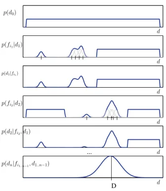
At the beginning of the depth estimation, the prior is uniform on the line of view. No information about the dis-tance between the object and the camera is indeed available. The top frame of (6) represents the a priori knowledge at the initialization step. The probability density function is uniform. The second frame is the probability density function corresponding to the first measurements. Some features have been matched giving some evidence on the object depth. They are represented as gaussian functions to model measure errors. The third frame is the posterior. It is computed using the Bayes formula and the pdf of the two first frames. It is used as the prior of the next step. The next frame represents a new measurement set. Fifth frame is the posterior computed using the fourth and the third frame pdf, and so on, until the pdf converges to an unimodal distribution that has a maximum at the object estimated depth (see Fig. 6).
The depth estimation is computed as the maximum of the posterior. To refine the estimation, the segment may be covered several times. Two stop criteria may then be used: a threshold on the maximum of the posterior or a measure of the information, such as Shannon’s entropy. A compromise has to be reached between the accuracy of the estimation and the time spent to compute it.
As soon as the stop criterion is reached, an estimation of the object depth is returned allowing the eye-in-hand camera
... D d d d d d d p(d2|fi2, d1) p(dn|fi1..n−1, d1..n−1) p(fi2|d2) p(d1|fi1) p(fi1|d1) p(d0)
Fig. 6. Bayesian decision process: 1) The top frame represents the a priori knowledge at the initialization step. The pdf is uniform between the minimum and maximum depth and null elsewhere. 2) The second frame is the pdf corresponding to the first measurements. Some features have been matched and their projection on the 3D line are represented by some Gaussian functions. 3) using Bayesian equation (7) the posterior is calculated. It is used as the prior of the next step. 4) A new set of measurements is taken given a new pdf. 5) Posterior is computed using the pdf of the third and fourth frame, and so on, until the pdf converges to a Gaussian distribution that has a maximum at the object estimated depth.
to center the corresponding part of the segment. The process succeed when the object falls in the eye-in-hand camera view.
D. Experimental results
This section presents a typical execution of the application presented above. The experimental setup is presented in Figure 4 and 7. The eye-in-hand camera is mounted on the end effector of a 6 degree of freedom arm robot. The eye-to-hand camera is fixed and its field of view covers the whole robot workspace. As figure 7 shows, the scene is quite complex and the background is highly textured. The algorithm is launched as soon as the user has clicked on the object to grasp in the eye-to-hand camera’s view.
First, the epipolar line is centered. When the main task error falls below a certain threshold the secondary task is activated and epipolar line, that is the intersection between the line of view and the arm workspace, is scanned. While the eye-in-hand camera is covering the segment, the object is searched in the eye-in-hand view. The eye-in-hand camera keeps moving until the object is found.
We first present the results of the visual based control scheme and then the results of the depth estimation.
Fig. 7. Experimental setup: the scene is complex and the background is textured. The two camera locations are highlighted. Top right, the eye-To-Hand view is display with the clicked pointcfp. The green line represents
the line of view associated withcfp
0 10 20 30 40 50 60 70 80 90 0 0.5 1 1.5 2 2.5 3 Iteration error (m) e1 e2
Fig. 8. Task error during a visual servoing execution on a motionless target
1) Epipolar based visual servoing: The control scheme
results are summed up in Figures 8 and 9. Figure 8 shows the evolution of the two taskse1ande2during the regulation. The execution starts with only the main task. Then, at iter-ation 30, the main task error passes below a fixed threshold and the secondary task is launched. The point to center is the first extremity of the 3D segment. The secondary task error decreases while the main task error remains zero. At iteration 60, the segment extremity is reached. The point to center is switched to the second extremity of the segment. The secondary task error increases suddenly when the referenced point is changed, and then, it is regulated according to an exponential decrease. To refine the depth estimation, the point to center may be switched to the first extremity of the segment and so on, until the estimation is reliable enough, according to the chosen criterion (minimum of entropy or maximum of the posterior). Figure 9 gives the robot-end-effector velocities. The execution of the secondary task at iterations 30 and 60 implies, as expected, a pure rotational
motion around the y axis of the Rcm frame.
To test the robustness of the proposed approach, we perform others experiments with applying small motions to the object.A simple tracking algorithm based on local
appearance gives the coordinates of cfp at each step of the
servo loop, so that we can compute each time the epipolar line and the extremities of the segment. The control law thus takes into account the movement of the object. The results
0 10 20 30 40 50 60 70 80 90 −4 −2 0 2x 10 −4 Trans. Velocities 0 10 20 30 40 50 60 70 80 90 −0.04 −0.02 0 0.02 0.04 0.06 Iteration Rot. Velocities vx vy vz ωx ωy ωz
Fig. 9. Velocities of the eye-in-hand camera during the servoing on a motionless target
obtained in [16] show that the task is hardly disturbed by the object motion. It is mainly due to the use of visual servoing that is known to be stable to approximation in model of the system
2) Searching for the object: As soon as the segment is
in the eye-in-hand view, the recognition algorithm starts and the object is searched. The object used are taken from the every-day life, ranging from highly textured commercial rice box to white plastic animals (see Fig. 7).
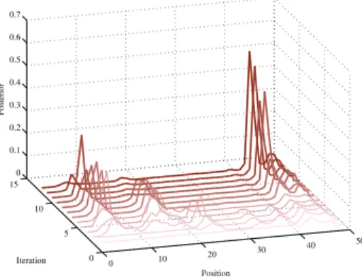
SIFT features are extracted from eye-in-hand views and matched with the features extracted from the region of interest of the eye-to-hand camera view. The likelihood of the estimated object depth on the line of view is then computed using the projection of the matched features on the 3D segment. The posterior is computed using (7). The process is repeated until the maximum posterior reaches a certain threshold. Figure 10 presents the evolution of the a posteriori probability density function of the object depth. A clear maximum quickly appears and the object is easily found within 10 iterations of the recognition process (10 views taken). The object is finally found in the camera view. Its distance from the camera center is approximately 1,4m and it is center in the eye-in-hand camera view.
The algorithm is stable despite some slight motions of the targeted object since the searching area is updated at each step of the servo process, thus, the process is stable to small movement of the wheelchair inducing motion of the eye-to-hand camera. It saves the end user many actions to bring the object in the view of the eye-in-hand camera. His action is restricted to one solely click. The proposed method will be
deployed on the MANUS robotic arm. Handicapped people
will evaluate it in a house environment using everyday life objects.
IV. CONCLUSIONS AND FUTURE WORKS In this document we have described a method aiming at reducing down to one click (or equivalent) the action needed by an operator to trigger a grasping action of a robot. The method presented relies on usage of a low cost Web-cam and
0 10 20 30 40 50 0 5 10 15 0 0.1 0.2 0.3 0.4 0.5 0.6 0.7 Position Iteration Posterior
Fig. 10. Depth estimation using Bayesian decision process: evolution of the posterior probability density function over the time. The further graph allows to estimate the depth of the object on the view line. The 3D segment is 1,5m long has been sampled in 50 bins. The object is thought to be at an estimated depth of 1.4m.
visual servoing technique. The method has been designed to be independent from the object. It doesn’t need mark on the object, or geometrical model, or database. The method is straightforward to learn and very simple to use, providing this way the intuitive man machine interface we are looking for to provide severely disabled people with a simple function to grasp objects in their environment. Future work will be focused on conception of a real time obstacle avoidance method letting the end user free from surveillance of robot motion during the approach phase of grasping. On another hand, tries will be made with quadriplegic patients and valid people to evaluate the method.
REFERENCES
[1] J R Allen, A Karchak, and E.L. Bontrager. Design and fabrication of a pair of rancho antropomorphic arm. Technical report, Rancho Los Amigos Hospital, Inc, 1972.
[2] R.M. Alqasemi, E. J. McCaffrey, K D Edwards, and R. V. Dubey. Analysis, evaluation and development of wheelchair mounted robotic arms. In IEEE Int. Conf. on Rehabilitation Robotics, pages 469–472, 2005.
[3] C Balaguer, A Gimenez, A Jardon, R Cabas, and R Correal. Live experimentation of the service robot applications for elderly people care in home environments. In IEEE Int. Conf. on Robotics and
Automation, 2005.
[4] C Balaguer, A Giminez, A J Huete, A M Sabatini, M Topping, and G Bolmsjo. The mats robot, service climbing robot for personal assistance. IEEE Robotics and Automation Magazine, pages 2–9, March 2006.
[5] R. Basri, E. Rivlin, and I. Shishoni. Visual homing: Surfing on the epipoles. Int. Journal of Computer Vision, 33(2):117–137, February 1999.
[6] T. Bayes. An essay towards solving a problem in the doctrine of chances. Phil. Trans., 3:370–418, 1763.
[7] Z. Bien, J.S. Kim, M.J. Chung, Kwon D.S., and Chang P.H. Devel-oppement of a wheelchair-based rehabilitation robotic system (kares ii) with various human robot interaction interfaces for the disabled. In Int.
Conf. on Advanced Intelligent Mechatronics, volume 20. IEEE/ASME,
2003.
[8] R. Bischoff. Design concept and realization of the humanoid service robot hermes. In A. Zelinsky, editor, In Field and Service Robotics,, pages 485–492. London, springer edition, 1998.
[9] F. Bley, M. Rous, U. Canzler, and K. Karl-Friedrich. Supervised navigation and manipulation for impaired wheelchair users. IEEE
[10] M Busnel, R Cammoun, F Coulon-Lauture, J-M Detriche, G Le Claire, and B Lesigne. The robotized workstation ”master” for users with tetraplegia: Description and evaluation. Journal of Rehabilitation
Research and Development, 9(3), 1999.
[11] M. Busnel, R. Gelin, and Lesigne B. Evaluation of a robotized master/raid workstation at home : protocol and first results. In IEEE
Int. Conf. on Rehabilitation Robotics, 2001.
[12] A Casals, R Villa, and D Casals. A soft assistance arm for tetraplegics. In 1st TIDE Cong., pages 103–107, April 1993.
[13] F. Chaumette and S. Hutchinson. Visual servo control, part i : Basic approach. IEEE Robotics and Automation Magazine, 13(4):82–90, December 2006.
[14] P Dario, E Guglielmelli, C Laschi, and G Teti. Movaid: A mobile robotic system residential care to disabled and elderly people. The First MobiNet Symposium, 1997.
[15] R. O. Duda, P.E. Hart, and Stork D. G. Pattern Classification, second
edition. Wiley Interscience Publication, 2001.
[16] C Dune, E Marchand, and C Leroux. One click focus with eye-in-hand/eye-to-hand cooperation. In IEEE Int. Conf. on Robotics and
Automation, Roma, 2007.
[17] H. Eftring and K. Boschian. Technical results from manus user trials. In IEEE Int. Conf. on Rehabilitation Robotics, pages 136–141, 99. [18] M. Elena, M Critiano, F. Damiano, and M. Bonfe. Variable structure
pid controler for cooperative eye-in-hand/eye-to-hand visual servoing. In IEEE. Int. Conf. on Control Applications, ICCA’03, pages 989–994, Istambul, Turkey, 2003.
[19] B. Espiau, F. Chaumette, and P. Rives. A new approach to visual servoing in robotics. IEEE Trans. on Robotics and Automation, 8(3):313–326, June 1992.
[20] G. Flandin, F. Chaumette, and E. Marchand. Eye-in-hand / eye-to-hand cooperation for visual servoing. In IEEE Int. Conf. on Robotics
and Automation, pages 2741–2746, San Francisco, CA, April 2000.
[21] B. Graf, M Hans, and R D Schraft. Care-o-bot ii:development of a next generation robotic home assistant. Autonomous robots, 2004. [22] R. Hartley and A. Zisserman. Multiple View Geometry in Computer
Vision. Cambridge University Press, 2001.
[23] S. W. Harwin, T. Rahman, and A. Foulds, R. A review of design issues in rehabilitation robotics with reference to north american research.
IEEE Trans. on Rehabilitation Engineerinng, 3, March 1995.
[24] M Hillman. rehabilitation robotics from past to present- a historical perspective. In IEEE Int. Conf. on Rehabilitation Robotics, April 2003. [25] P. Hoppenot and E. Colle. Localization and control of a rehabilitation mobile robot by close human - machine cooperation. IEEE Trans. on
Neural Systems and Rehabilitation Engineering, 9:1534–1724, 2001.
[26] R. Horaud, Knossow D., and M. Michaelis. Camera cooperation for achieving visual attention. Machine Vision and Applications, 16(6):1– 12, 2006.
[27] S. Ishii, S. Tanaka, and F. Hiramatsu. Meal assistance robot for severely handicapped people. In IEEE Int, Conf on Rehabilitation
and Automation, pages 1308–1313, San Francisco, USA, 1995.
[28] T. Jones. Raid : Toward greater independence in the office& home environment. In IEEE Int. Conf. on Rehabilitation Robotics, pages 201–206, 1999.
[29] N Katevas, Harwin W, Heck H, and Aldon MJ et al. Mobile robotics and automation in healthcare and rehabilitatin. Mobile Robotics in Healthcare, 2001.
[30] K. Kawamura and M. Iskarous. Trends in service robots for the disabled and the elderly. Special session on service robots for the disabled and elderly people, 1994.
[31] S. Kawamura, K.and Bagchi, M. Iskarous, R. T. Pack, and A. Saad. An intelligent robotic aid system for human services. In AIAA/NASA
Conf. Intelligent Robotics Fields, volume 2 of Factory, Service Space,
pages 413–420, March 1994.
[32] J. Kephart and D. Ches. he vision of autonomic computing. Computer
Magazine, 36(1):41–50, 2003.
[33] Duimel Kwee H H, J J, SMits, A A J.J, Tuinhofde Moed, and J A van Woerden. The manus wheelchair-borne manipulator : System review and first results. In IARP, 2nd Workshop Medical and Healthcare
Robotics, pages 385–395, 1989.
[34] C Leroux, G Chalubert, O Tahri, S Schmutz, N Biard, I Lafont, Dsert J-F, and R Alexandre, J Mand Gelin. Interface intelligente pour la saisie d’objets robotise, handicap 2006. In National Conf. Handicap, paris, june 2006.
[35] C Leroux, M Guerrand, C. Leroy, Y Masson, and B. Boukarri. Magritte: a graphic supervisor for remote handling interventions. In
ESA Workshop on Advanced Space Technologies for Robotics and Automation, ’ASTRA 2004, Noordwijk, The Netherlands, November
2004.
[36] V. Lippiello, B. Siciliano, and L. Villani. Eye-in-hand/eye-to-hand multi-camera visual servoing. In IEEE Int. Conf. on Decision and
Control, CDC’05, pages 5354 – 5359, Seville, Spain, December 2005.
[37] D.G. Lowe. Distinctive image features from scale-invariant keypoints.
Int. Journal of Computer Vision, 60(2):91–110, 2004.
[38] R. Mahoney. The raptor wheelchair robot system. In IEEE Int. Conf.
on Rehabilitation Robotics, pages 135–141, Evry, France, 2001.
[39] H. Neveryd and G. Bolmsj. Walky, an ultrasonic navigating mobile robot for the disabled. In TIDE, pages 366–370, Paris, France, 1995. [40] World Health Organization. World health organization assessment, classification and epidemiology group, international classification of functioning and disability. World Health Organization, July 1999. [41] J. Piazzi, D. Prattichizzo, and N. J. Cowan. Auto epipolar visual
servoing. In IEEE Int. Conf. on Intelligent Robots and Systems,
IROS’04, volume 1, pages 363–368, Sendai, Japon, October 2004.
[42] P. Rives. Visual servoing based on epipolar geometry. In IEEE Int.
Conf. on Intelligent Robots and Systems, IROS’00, volume 1, pages
602–607, Takamatsu, Japan, November 2000.
[43] G.R.B.E. Rmer, A. Peters, E. Koerhuis, and H.J.A Stuyt. Assistive robotic manipulator (arm): Cost-savings and economic benefits.
Inter-national Journal of Assistive Robotics and Mechatronics, pages 20–25,
june 2006.
[44] J.P. Sousa and D. Garlan. Aura: an architectural framework for user mobility in ubiquitous computing environments. In IEEE/IFIP
Conference on Software Architecture, pages 29–43, August 2002.
[45] R. Soyama, S. Ishii, and A. Fukase. The development of meal-assistance robot ’myspoon’. In IEEE Int. Conf. on Rehabilitation
Robotics, pages 88–91, 2003.
[46] J. Topping, M.and Smith. The developpement of handy 1 , a reha-bilitation robotic system to assist the severely disabled. In Industrial
robot, pages 316–320. 1998.
[47] M. Topping, H. Heck, G. Bolmsjo, and D. Weightman. The develop-ment of r.a.i.l. In TIDE, pages 23–25, 1998.
[48] H F M Van der Loos. Va/stanford rehabilitation robotics research and development program: Lessons learned in the application of robotics technology to the field of rehabilitation. IEEE Trans. on Neural
Systems and Rehabilitation Engineering, 3:46–55, March 1995.
[49] H F M Van der Loos, J J Wagner, N Smaby, K Chang, O Madrigal, L J Leifer, and O Khatib. Provar assistive robot system architecture. In IEEE Int. Conf. on Robotics and Automation, Detroit, May 2000. [50] I Volosyak, Ivlev O., and Graser A. rehabilitation robot friend ii
-the general concept and current implementation. In IEEE Int. Conf.
on Rehabilitation Robotics, pages 540–544, Chicago, IL, USA, June
![Fig. 1. Survey on the interest of disabled people for grasping and releasing objects [3]](https://thumb-eu.123doks.com/thumbv2/123doknet/13049658.382978/2.918.498.817.258.415/fig-survey-disabled-people-grasping-releasing-objects.webp)
![Fig. 2. four types of robots for disabled people : a) workstation MAS - -TER [11] ; b) ISAC stand alone Robot [31]; c) Victoria wheelchair mounted robot [9] d) Care-O-Bot mobile manipulator [21]](https://thumb-eu.123doks.com/thumbv2/123doknet/13049658.382978/3.918.87.442.81.436/robots-disabled-people-workstation-victoria-wheelchair-mounted-manipulator.webp)
![Fig. 3. The A VISO system consists of a M ANUS arm [17], [33] mounted on a wheelchair, a stereo vision system fixed on the end effector of the arm, a graphical interface displayed on a monitor, any device adapted to the user’s handicap (speech recognition,](https://thumb-eu.123doks.com/thumbv2/123doknet/13049658.382978/4.918.505.803.100.315/consists-wheelchair-effector-graphical-interface-displayed-handicap-recognition.webp)