HAL Id: hal-02366808
https://hal.archives-ouvertes.fr/hal-02366808
Submitted on 16 Nov 2019
HAL is a multi-disciplinary open access archive for the deposit and dissemination of sci-entific research documents, whether they are pub-lished or not. The documents may come from teaching and research institutions in France or abroad, or from public or private research centers.
L’archive ouverte pluridisciplinaire HAL, est destinée au dépôt et à la diffusion de documents scientifiques de niveau recherche, publiés ou non, émanant des établissements d’enseignement et de recherche français ou étrangers, des laboratoires publics ou privés.
multiplexing in MgO-doped fibers
Aidana Beisenova, Aizhan Issatayeva, Sultan Sovetov, Sanzhar Korganbayev,
Madina Jelbuldina, Zhannat Ashikbayeva, Wilfried Blanc, Emiliano Schena,
Salvador Sales, Carlo Molardi, et al.
To cite this version:
Aidana Beisenova, Aizhan Issatayeva, Sultan Sovetov, Sanzhar Korganbayev, Madina Jelbuldina, et al.. Multi-fiber distributed thermal profiling of minimally invasive thermal ablation with scattering-level multiplexing in MgO-doped fibers. Biomedical optics express, Optical Society of America - OSA Publishing, 2019, 10 (3), pp.1282. �10.1364/BOE.10.001282�. �hal-02366808�
Multi-fiber distributed thermal profiling of
minimally invasive thermal ablation with
scattering-level multiplexing in MgO-doped
fibers
A
IDANAB
EISENOVA,
1A
IZHANI
SSATAYEVA,
1S
ULTANS
OVETOV,
1S
ANZHARK
ORGANBAYEV,
2M
ADINAJ
ELBULDINA,
1,2Z
HANNATA
SHIKBAYEVA,
1,2W
ILFRIEDB
LANC,
3E
MILIANOS
CHENA,
4S
ALVADORS
ALES,
5C
ARLOM
OLARDI,
1ANDD
ANIELET
OSI1,2,*1Nazarbayev University, Department of Electrical and Computer Engineering, 010000 Astana, Kazakhstan
2Laboratory of Biosensors and Bioinstruments, National Laboratory Astana, 010000 Astana, Kazakhstan
3Université Côte d’Azur, INPHYNI–CNRS UMR 7010, Parc Valrose, 06108 Nice, France
4E. Unit of Measurements and Biomedical Instrumentation, University Campus Bio-Medico of Rome, via Alvaro del Portillo 21, 00128 Rome, Italy
5Institute of Telecommunications and Multimedia Applications (iTEAM), Universitat Politècnica de València, Camino de Vera s/n, 46022 Valencia, Spain
*daniele.tosi@nu.edu.kz
Abstract: We propose a setup for multiplexed distributed optical fiber sensors capable of
resolving temperature distribution in thermo-therapies, with a spatial resolution of 2.5 mm over multiple fibers interrogated simultaneously. The setup is based on optical backscatter reflectometry (OBR) applied to optical fibers having backscattered power significantly larger than standard fibers (36.5 dB), obtained through MgO doping. The setup is based on a scattering-level multiplexing, which allows interrogating all the sensing fibers simultaneously, thanks to the fact that the backscattered power can be unambiguously associated to each fiber. The setup has been validated for the planar measurement of temperature profiles in ex vivo radiofrequency ablation, obtaining the measurement of temperature over a surface of 96 total points (4 fibers, 8 sensing points per cm2). The spatial
resolution obtained for the planar measurement allows extending distributed sensing to surface, or even three-dimensional, geometries performing temperature sensing in the tissue with millimeter resolution in multiple dimensions.
© 2019 Optical Society of America under the terms of the OSA Open Access Publishing Agreement
1. Introduction
Minimally invasive thermotherapies are playing a significant role in cancer treatment, for the removal of solid tumors after their diagnosis [1–3]. Minimally invasive methods based on thermal ablation make use of a minimally invasive applicator, inserted in situ to deliver heat in the form of electromagnetic energy to the surrounding tissue. Tumor cells mortality is a function of temperature and exposure time [4,5], with cytotoxicity phenomena appearing over 42 °C; temperatures higher than 60 °C induce protein coagulation, resulting in a rapid cellular death [4].
Thermal ablation methods are successful in providing percutaneous treatments for solid tumors having small size in liver [3], kidney [6], thyroid [7], and brain [8] among others. Four principal methods have been implemented in clinical practice: radiofrequency ablation (RFA), which makes use of the difference of potential between an active electrode positioned on the applicator tip and a passive electrode placed in a neutral spot [1,6]; microwave ablation
#346894 https://doi.org/10.1364/BOE.10.001282 Journal © 2019 Received 27 Sep 2018; revised 10 Jan 2019; accepted 14 Jan 2019; published 19 Feb 2019
(MWA) uses a generator emitting around 2.4 GHz to deliver an alternate power to the tissue, which acts as an electrical load [9]; laser ablation (LA), in which a solid-state laser delivers a continuous power to the tissue through one or multiple delivery fibers [7]; high-intensity focused ultrasound (HIFU), a non-contact method, in which an arrayed element focuses an ultrasound beam scanning the target tissue [10]. Among these methods, RFA and MWA have been appreciated for their capability to treat wide portions of tissue and rapid ablation process, and recent results show that these methods can be complemented with nanoparticles to extend the ablated tissue by a significant amount [11].
One of the main challenges of thermal ablation is the measurement of temperature across the treated regions [12] because the cellular mortality is a direct function of thermal dosimetry. This task is challenging since all thermal treatments generate heat patterns in the tissue that have high spatial and temporal gradients, often overcoming 50 °C/mm and 5 °C/s [13]. Therefore [4], the possibility to measure in real-time the temperature profile resolving thermal patterns is important to estimate the ablated portion of the tissue [14]; this allows verifying that the entire tumor has been treated, making thermometry the most important control for RFA/MWA [12].
The classical method for measuring the temperature in situ makes use of thermocouples [15,16]. These sensors, however, have two major weaknesses: thermocouples, even when packaged in a miniature form factor, can affect the heating propagation due to the two metallic wires which represent their sensing part, and they measure the temperature in a single point, while they cannot measure a spatial profile of temperature. Thermocouples are mounted on the tip of modern commercial RFA devices [17]. An alternative to thermocouples is thermal imaging [18–20], which uses magnetic resonance imaging (MRI) or computed tomography (CT) to perform thermal imaging on the tissue exposed to ablation. In these techniques, the temperature change is inferred from images of temperature dependent properties of biological tissue [18,19]. MRI thermometry is based on the dependence of several MR parameters on temperature. Among others, the relaxation times and the proton resonance frequency are the most employed in these fields [18]. This technique has been already used in vivo during different thermal treatments [20]. Basically, CT thermometry is based on the influence of the temperature on the phenomenon of Compton scattering. This influence causes a decrease of the attenuation of X-ray beam with temperature which can be observed on the CT images [20]. Both these techniques have the main advantages to be non-invasive (or contactless) and to provide a three-dimensional temperature map around the tissue. Otherwise, the main concerns in the use of these techniques are the cost of MR scanner and specific sequences for obtaining good sensitivity to temperature, the need of using MR-compatible devices (for MR thermometry), the need to an X-ray dose to the patient (for CT-thermometry), and the presence of artefact due to patient respiratory movement [18,19].
Fiber optic sensors (FOS) represent the main alternative to these methods and have been recently extensively applied for temperature sensing in real time during RFA and MWA [13,14]. FOS are an excellent candidate to outperform thermocouples and MRI, because they have miniature form factor (smaller than RFA/MWA applicators), they are biocompatible in accordance to ISO 10993 standard [21] and have an instantaneous response. Most importantly, FOS have the unique property of detecting temperature patterns on a single fiber with resolutions between 0.1 mm and 10 mm [14], and the possibility of multiplexing among multiple fibers to detect the temperature pattern in one- or two-dimensional geometries [22] in a single scan. Fiber Bragg Gratings (FBGs) have been used for this task: FBG arrays make use of wavelength-division multiplexing and multiple channel interrogators to detect temperature patterns with spatial resolution included within 5 mm and 10 mm [12,14]; however, the spatial resolution is coarse compared to the thermal gradients at which the tissue is exposed in RFA [12]. An alternative is chirped FBGs [13], which can virtually reduce the resolution to the millimeter scale; however, chirped grating sensing system operate under the
assumption that the temperature pattern is known a priori, such as a Gaussian function, as reported by Korganbayev et al. in 2018 [23].
Distributed sensing stands as the most modern approach for temperature sensing in thermal ablation, using methods derived from optical frequency domain reflectometry (OFDR) [14]. An OFDR system based on white-light interferometry interrogates distributed reflections occurring in the fiber [24,25]. The most important OFDR implementation for sensing is optical backscatter reflectometry (OBR), whereas the distributed reflections are the random Rayleigh backscattering components naturally occurring on any standard fiber, labeled as the “signature”. The OBR system is an OFDR with detectors sufficiently accurate to detect the fiber signature in each location and estimate the spectral shift of each signature [26–28]. After being pioneered and consolidated by Froggatt et al. [26,27], and industrialized in the OBR instrument [28], distributed sensing based on OBR has been first demonstrated in RFA by Macchi et al. [29]. OBR allows an inline measurement of temperature with resolution below the millimeter scale [14,28,29].
A major weakness of OBR is that this method is not suitable for multiplexing onto multiple fibers. It is possible to use a switch to connect multiple channels, but since each channel requires an independent triggering and the measurement is relatively slow, performing a multi-fiber measurement at a speed inferior to 1 s is not feasible. Because of this drawback, OBR measurements are inherently single-channel, resulting in a one-directional inline measurement of temperature [14]. It is possible to bend the sensing fiber around the tissue in order to obtain a multi-dimensional measurement, as reported in [29]; however, this type of layout of the fiber is suitable only in investigations performed in the laboratory and cannot mimic a percutaneous insertion of the sensor as in [13] [22,23]. The detection of a planar temperature distribution with FOS, using a setup that can be percutaneously inserted in the tissue, has been reported in [22,30] using FBG arrays, however the 1-cm spacing between each grating element limited the resolution to the centimeter level, while OBR can operate at few millimeters or below.
In this work, we propose a new method to overcome this scenario, that makes use of specialty fibers and an architecture hereby defined as “scattering-level multiplexing” (SLMux). The 2 building blocks of this concept are the use of a fiber doped with MgO-based nanoparticles that has a backscattering power of 36.5 dB larger than a standard single-mode fiber, used as sensing elements, and a matrix of fiber extenders that displaces the position of each sensor such that the scattering components do not overlap in length. For each location we observe the overlap of the scattering components of multiple fibers; however, since the sensing fibers backscatter a power orders of magnitude larger than each other fiber, it is possible to unambiguously demodulate each sensing fiber. In practice, this architecture allows detecting multiple sensing regions on a plurality of fibers, maintaining the same spatial resolution of the OBR technique. The MgO-doped fiber has a thermo-optic coefficient similar to silica fibers.
This concept allows extending OBR from one-dimensional to two-dimensional (planar) temperature measurements in thermal ablation. An experimental setup has been designed to perform a temperature detection over 4 sensing fibers, achieving a total of 96 sensing points on a surface of 900 mm2. This highly resolved temperature measurement allows extending
OBR to the real-time measurement of temperature spatial distribution over the inner plane of thermal ablation, providing a valuable alternative to thermal imaging at a simpler implementation.
2. Experimental setup
2.1 Experimental setup
The experimental setup, embodying both the RFA setup and the distributed sensing system, is sketched in Fig. 1, while Fig. 2 shows photographic views.
The RFA module), con 160 mm of electrode (AE to a metallic p W at 450 kH available and aligned with measured by tissue resistan decreases unt impedance to RF power as ETS-D5) has ablation. This as hepatocellu positioned on Fig. 1 the w with a a secti core. relativ The meas operates as an represents a tr the spatial res 1200 mm tak connected to setup is base nected to a re length. The a E) having a con plate that is us Hz. Measureme d refreshed unt the European the RF genera nce at the sta til the water
abruptly rise. the impedanc been used to s RFA setup, d ular carcinoma the patient’s s . Schematic of the whole setup, includ applicator introduc ion of the core of t (c) Geometrical sk ve positions with r surement setup n OFDR with rade-off betwe solution has be king into acco a cascade of th ed on a RF g esearch-grade s applicator has nic shape of 1 ed to host the ents have been til the experim n Union “Thre ator in real tim art of the exp
components o The RF gener ce reaches the o measure the derived from [1 a, whereas the spine [1]. e RFA ablation an ding OBR-based s ced into the phanto
the sensing fiber, h ketch of the positio respect to the xy co
p is based on variable spatia en spatial reso een set to 2.5 m
unt all the 4 hree 1x2 wideb generator (RFG single-tip appl a cylindrical cm height. Th phantom. The n performed ex ment duration, ee Rs” princip me through an periment is 12 of the tissue r rator has been s
measured val reference tem 13,22], mimics applicator is p
nd distributed sens sensing with fiber om. (b) SEM (sca highlighting the pr on of the RF appli oordinates; all size
a commercia al resolution. T
lution and tem mm, while the fibers in this band splitters o G, Leanfa s.r. icator having shape termin he passive elect RF power use x vivo on porci following the ple. The impe n impedance m
20 Ω, then re reach the boil
set on “safe m lue of 700 Ω. mperature of th s the treatment percutaneously sing interrogation rs and extenders, anning electron mi resence of MgO n icator and the fibe es are in mm. al OBR (Luna The choice of mperature accur overall sensing window. The operating in th .l., Hybrid RF diameter of 3 nated with a t trode (PE) is c ed for experime
ine liver, comm method in [22 edance of the meter. The valu esistance prog ling point, cau mode”, discontin A thermocou he tissue at the
of hepatic tum y inserted, and
setup. (a) View of and the RF setup icroscope) view of nanoparticles in the ers S1-S4, and their
a Inc., OBR46 the sensing pa racy; in the exp g length has be OBR output he third optical FA/MWA mm and tip active connected ents is 40 mercially 2] that is tissue is ue of the gressively using the nuing the uple (IKA e start of mors such the PE is f p f e r 600), that arameters periments een set to has been window,
i.e., the C ba fibers, splitter SMF-28) whi characteristics The SLMu length that h (labeled S1, S
spot scan fea Rayleigh bac signature is a estimate the w the temperatu different fiber fibers, using a This setup the high-scat recorded by multiplexed v S1-S4, the OB geometry as maintaining a Fig. 2 scatte after t In the set proximity of reported in [2 order to obtai fiber has been
and between 1 rs, and the ext ile the sensing s.
ux setup is bas ave the role t S2, S3, S4). The ature, detectin ckscattering sp acquired at the wavelength shi ure distribution r length that t a fusion splicer p extends over tering fibers a the OBR, bu variable is the BR can detect in Fig. 1 it a sub-centimete 2. Photograph of t ring trace acquired the RFA experime
tup, the sensin the applicator 2] has been us in a methodolo n set to 5 mm, 530 an and 15 tenders are ba g fibers are bas sed on 4 extend to delay the re e OBR is confi ng with 0.3 H pectrum at ea e experiment s fts in each loca n [26,31]. The
akes into acco r (Fujikura
12-the work propo are not used ut rather to c scattering leve a distributed is possible to er scale resolut the experimental s d on the OBR. (c) nt; ruler scale in c ng fibers have r, in order to m sed, using a cat ogy that mimic while the lengt
565 nm. All o ased on standa sed on MgO-d ders (labelled E elative location figured to oper Hz speed the f ch location [2 tart, and a mu ation due to tem
length of each ount also the l
S). osed by Parent to improve th create a new el that changes temperature a o obtain a tw tion in both axe
setup. (a) View o View of the ablat m.
been position map the tempe theter to insert s in vivo opera th of each sens optical connect ard single-mod doped fibers an E1, E2, E3, E4) n of each Mg rate in distribut fiber signature 28]. For each utual correlatio mperature vari h extender has ength of the s t et al. for strai he amount of multiplexing s in each locati and by placing wo-dimensional es.
of the whole setup ted phantom and t
ned in situ in erature pattern and removing ation [12]. The sing region is a tions, includin de fiber (SMF, nd have high-s each having a gO-doped sens uted sensing mo e correspondin h sensing loca on algorithm i iation, hence e s been set by s splitters and th in sensing [31] f scattered pow domain, whe ion. Within eac g the fibers in l temperature
p. (b) Inset on the the sensor location
the phantom n of RFA. The g it after the ins
e distance betw approximately ng lead-in , Corning scattering a different sing fiber ode, with ng to the ation, the s used to estimating splicing a he lead-in ], because wer level ereas the ch sensor a planar mapping e n tissue, in e method sertion, in ween each 180 mm,
with a “useful” region of 60 mm where a temperature change occurs. With the setup arranged in this way, it is possible to obtain 96 (4 fibers × 24 useful sensing point per fiber) over an area of 900 mm2 (60 mm × 15 mm).
The photographic view of the setup is shown in Fig. 2, including both the RF module and the OBR sensing system. Extenders have been laid out on a plate in order to maintain the fiber bending unaltered during measurements. The phantom after ablation is shown in Fig. 2(c), whereas the sensors are positioned on the same plane of the RFA applicator. The photo has been obtained by manually cutting the phantom, which caused fibers to slightly move from their location during the measurement; however, this figure is indicative to show the size of the ablated tissue.
2.2 Fiber characterization and interrogation
The preform was fabricated by conventional MCVD (Modified Chemical Vapor Deposition) process [32]. A Ge-doped silica porous layer of the core was immersed three times with 5 mL of the doping solution injected in the horizontally rotating tube. The composition of the ethanol-based doping solution is 0.1 mol/L of MgCl2 and 10−4 mol/L of ErCl3. The porous
layer was dried at 1000°C under an oxygen gas flow, then sintered at 1800°C. The tube was collapsed into the preform by heating above 2000°C. The diameter of the preform was around 10 mm with a 0.8 mm core diameter. The optical fiber was drawn on a drawing tower by heating the preform at approximately 2000°C. The external diameter of the fiber was 125 µm while the core diameter is about 10 µm.
The compositions of the optical preform and fiber were measured using Energy Dispersive X-ray (EDX) analyses. The average magnesium and germanium concentrations vary along the length (axial direction) of the fiber. The highest magnesium and germanium concentrations are 1.7 and 0.4 at.%, respectively. The introduction of magnesium triggers the formation of nanoparticles through the phase separation mechanism due to high temperatures reached during the fabrication [33]. The exact composition of the nanoparticles is unknown for this fiber, but it has been reported previously for other fibers where the nanoparticles are enriched with Mg [34].
Fig. 3. Thermal response of the MgO-doped sensing fiber.
The thermal response of the fiber is shown in Fig. 3, which has been estimated by inserting a spool of MgO-doped fiber on the surface of a hot plate, recording the plate temperature with a contact thermometer and measuring the wavelength shift of the fiber
Temperature (oC) 40 50 60 70 80 90 100 110 120 130 W av elength sh ift (n m) -0.2 0 0.2 0.4 0.6 0.8 1 1.2 Data Fit: 11.9 pm/oC
scattering signature with the OBR. The result is a linear sensitivity, with coefficient 11.9 pm/°C; this value is similar to silica fibers (~10.2 pm/°C), confirming that the doping concentration does not largely modify the thermo-optic coefficient of the fiber.
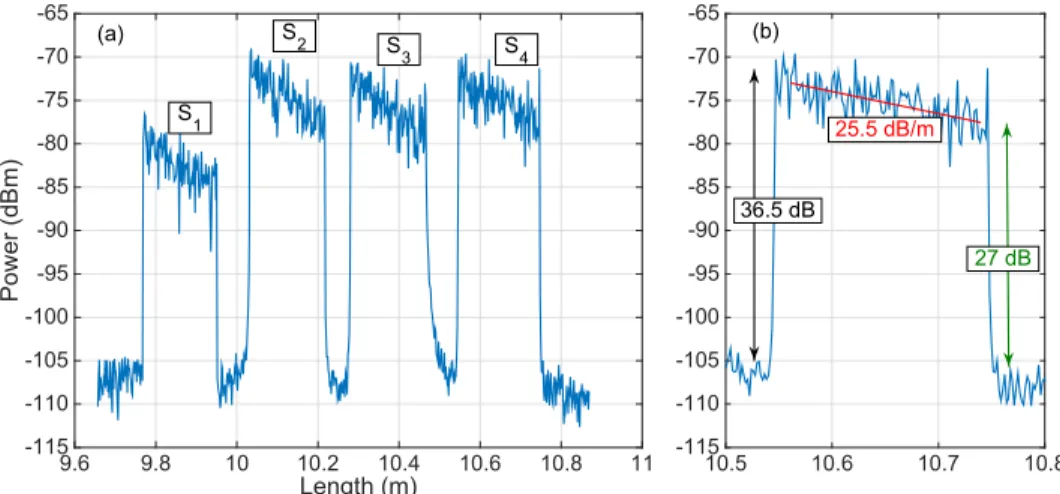
Fig. 4. Scattering characterization of the proposed setup. (a) Backscattered power as a function of length, as recorded on the OBR, for each fiber length. The chart identifies the 4 sensing regions S1 – S4, each having ~20 cm length of MgO-doped fiber. (b) Inset of the left chart,
showing an individual sensing region, with estimation of scattering “gain” G, fiber attenuation 2α, and signal-to-noise ratio.
The scattering characterization of the setup is shown in Fig. 4. In the left chart, it is possible to visualize the scattering trace, corresponding to the backscattered power as a function of length in the fiber. The chart identifies the 4 sensing regions, all designed using a length of ~18 cm of MgO-doped fiber, and the effect of the extenders: since each extender has a progressive length, the 4 locations can be unambiguously separated (S1: 9.77 – 9.95 m; S2:
10.03 –10.21 m; S3: 10.28 – 10.46 m; S4: 10.55 – 10.74 m). All the sensing regions are
enclosed within approximately 1 m of window on the OBR. All fibers have been cleaved prior to insertion in the tissue, and the local termination points of each fiber are not considered for the thermal map estimation.
The high scattering content shows the validity of the multiplexing concept and is reported in Fig. 4(b) for the longest extender region. While the SMF fiber has a scattering level of
−108.9 dBm and its attenuation is negligible over the short length of this setup, the magnitude of the MgO-doped fiber is −72.4 dBm, showing a scattering “gain” of G = 36.5 dB. In this framework, we define the gain as an additional intensity of the MgO-doped fiber that magnifies the scattering content, while there is no signal amplification [31]. The losses of the MgO-doped fiber are high and are accounted by estimating the slope of the trace in Fig. 4(b) as 2α = 25.5 dB/m cumulating the forward and backward losses that are accounted by the OBR.
The multiplexing concept works since the scattering trace of the sensing fibers is always much larger than the combination of all the scattering components of the SMF fibers. We can therefore define a signal-to-noise ratio (SNR) that relates to the only scattering component and is defined as the ratio of the scattering content of the MgO-doped fiber (signal) over the scattering of the SMF fibers that overlap to the signal at the same location (which acts as a noise that corrupts the scattering estimate). Since the MgO-doped fibers have high losses, the SNR is higher at the beginning of each sensing trace and is the lowest at the end of each sensing tract. In our setup, the worst case is observed for the sensor S1, since it has the
shortest extender and therefore it overlaps to all the other 3 SMF spans in the same location; on this specific channel, it also appears that losses are higher due to a splitter excess loss on
Length (m) 9.6 9.8 10 10.2 10.4 10.6 10.8 11 Po wer (d Bm) -115 -110 -105 -100 -95 -90 -85 -80 -75 -70 -65 10.5 10.6 10.7 10.8 -115 -110 -105 -100 -95 -90 -85 -80 -75 -70 -65 25.5 dB/m (a) (b) S1 S2 S3 S4 36.5 dB 27 dB
this specific channel. In any case, even at the tail of S1 the SNR is approximately 24 dB,
while Fig. 4(b) shows that the SNR is ~27 dB at the end of S4 region.
Empirically, we observe that a SNR of 20 dB is sufficient to ensure that the performances are limited by the trade-off between spatial resolution and accuracy of the OBR [31], without noticeable impairments due to multiple scattering components. This is also reinforced by the good noise rejection guaranteed by the mutual correlation algorithm. In comparison, FBG sensing networks operate with 20-30 dB of extinction ratio between adjacent gratings [22], confirming that the SLMux operates as a true multiplexing concept for fiber optic sensors.
Sensor interrogation has been performed by adjusting the OBR software, operating in distributed sensing, that allows continuous measurement of the scattering signatures. The mutual correlation algorithm has been used correlate the Rayleigh backscattering spectra within each gage length (i.e., the signatures), with the signatures measured at the start of the experiment. The thermo-optic coefficient previously estimated has been used to convert the wavelength shift into temperature variation for each measurement point. After the whole temperature distribution has been estimated, the thermal maps have been updated by converting each OBR location into its xy coordinates evaluated as in Fig. 1, making the conversion between the linear trace to the planar geometry. The spectral correlation output is independent upon the power level (which removes minor effects such as temperature-dependent loss of the MgO-doped fibers) and operates on an 8 pm grid, correspondent to 0.7 °C thermal resolution.
3. Results
The experiments have been carried out by obtaining the reference temperature and fiber signature during the initialization, and then turning on the RFA generator in safe mode. The RF power has been delivered to the tissue until the vaporization, where the tissue impedance overcomes the threshold of 700 Ω, and then the power has been automatically discontinued. The thermal maps have been obtained on the xy plane by processing the data from each sensing fiber: temperature has been sampled with 2.5 mm resolution along the x axis parallel to the RFA applicator (corresponding to the OBR spatial resolution), with 5 mm resolution along the y axis perpendicular to the RFA applicator (corresponding to the distance between adjacent sensing fibers), and with 0.33 s time resolution (corresponding to the OBR speed in single-scan). Multiple experiments have been performed, showing similar results; in the following, we report the result for the ablation shown photographically in Fig. 2(c) as a benchmark of the distributed sensing system.
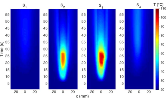
Fig. 5. Thermal maps reporting the measured temperature as a function of distance along the fiber (direction x) and time for each of the four sensing elements, located at coordinates y =
−7.5 mm (S1), y = −2.5 mm (S2), y = 2.5 mm (S3), y = 7.5 mm (S4).
In Fig. 5 we report the thermal maps obtained in this experiment, using the notation of [22] that reports the temperature as a function of distance along the fiber (x) and time elapsed. The thermal maps show the initial temperature rising, from the ~20°C room temperature, for as the RF power is dissipated on the tissue. The heating pattern progressively enlarged, as the impedance of the tissue decreased from the initial 120 Ω to ~85 Ω. In this moment, the heat pattern was recorded by both inner sensors S2-S3, with the sensor placed on the right of the
applicator observing a higher heating. This asymmetric pattern is confirmed by Fig. 2(c) and is largely due to the non-homogeneous properties of the tissue, including fat and capillaries that deviate the RF ablation pattern particularly for fast ablation phenomena [3]. Conversely, heat did not significantly propagate to the external fibers, that see a marginal increase of temperature. After 25 s the vaporization of the tissue occurs, causing the RF power to be discontinued; the consequence is the temperature drop, with a gradient that is steeper in the center where the RF power is discontinued and is lower in on the sides, due to the delays of heat propagation from inner parts of the tissue to the peripheral sides. The maximum temperature of 102.7°C has been observed after 25 s. The external sensors detect a heating process having a peak at 41 s and a maximum temperature of 42.4°C (S4) and 33.2°C (S1), 16
Fig. 6 elapse 4 × 17
This is an parts, and agr
The data i at each measu allows expand implementatio contours repo data have bee tissue on the inner portion reports the the appearing slig penetration, a 15 mm wide o tissue is cooli tails of the tis
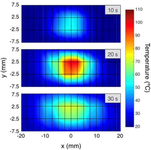
6. Two-dimension ed time (10 s, 20 s 7 sensing point, sp
n effect of heat ees with both t in Fig. 5 can b urement time t ding OBR me on. The two-d orting the isoth
en interpolated xy plane: afte
of the tissue ermal maps aft ghtly asymmet and the 60°C re on the x axis w ing, the tempe sue, however w
nal thermal maps, s, 30 s). The plain paced 5 mm on y a t propagation the simulative be combined to the temperature asurement in t dimensional m ermal curves ( d as in [30]. Th er 10 s during and the 60°C ter 20 s, close tric with the ri egion has an ex with a slight m erature remains without reachin reporting tempera considered is 15 × xis and 2.5 mm on
from the inner [35] and exper o generate bi-d e recorded on two dimension maps have been points held at he maps in Fig the heating p C threshold is to the RF pow ight part of the xtension that ap misalignment ty s high in the c ng the 60°C thr rature on the xy p × 40 mm, correspo n x axis. See Visua
r sides of the rimental [29] re dimensional th each xy coord ns and constitu n reported in the same temp g. 6 report the process, heat r not achieved wer discontinue e tissue having ppears 10 mm ypical of RFA center, and the
reshold.
plane for different onding to a grid of
alization 1.
tissue to the p esults of Macc ermal maps, th dinate; this arra utes the key o
Fig. 6, with perature [4]). In
estimate of th emains confin yet. The seco ed event. The a g a slightly de wide on the y [35]. At 30 s, heat propagat t f peripheral chi et al. hat report angement f SLMux the color nter-pixel he ablated ned in the ond chart ablation is eeper heat axis, and when the tes on the
The cinem heating proce measurement Finally, w which is a pi differential in peak tempera the differentia proximity of t they account pointing from approximately 6-7 have a sp fit between ac vicinity durin resolution is a Fig. 7 Time colder 4. Discussio The SLMux m division mult [37] reported inscribe senso method requi arbitrarily the in previous se Compared the spatial res ~0.1 mm (alth the spatial re methods [14], problem of FB the fiber pro strength. This increases the typical distan require remov Parent et different scatt sensing region matic of the th ess, are includ
time (data rate we can estimate ivotal informat nformation is r ature event (25 al of the temp the centers, the the two-dime m the colder y 5.6 °C/mm in patial resolution ccuracy and ab ng the insertio a good value fo 7. Temporal and sp gradients reported r to hotter points. on method propos tiplexing (SDM d an SDM me ors in each co ires all sensor e geometry of t ections. d to sensing ne
solution to the hough this val esolution is lim , and by the ne BG sensors in otective jacket s can be solve fiber thicknes nce between a ving the fiber ja
al. [31] repo
tering enhance ns, but rather to
hermal maps, ed as Visualiz e has been redu e the temperat tion to predict reported in Fig 5 s elapsed tim perature betwe e gradient reac ensional gradie to the hotter n proximity of n that is limite bsence of avera on along y; a or mini-invasiv patial temperature d in °C/s; (b) spat ed in this work M) method rep thod on a mu ore element. H rs to be on th the sensing net
tworks based o e millimeter sc lue leads to an mited both by eed to have a g monitoring of prior to insc ed either by re s, or by using adjacent gratin acket. orted high-scat ement; this me o improve the that contains zation 1, and s uced to 1 s to re ture gradients and investiga g. 7. For simp me). Temporal een two measu ches approxima ents of a scal point. The m f the applicator ed by the OBR aging effects, a as concluded i ve thermotherap gradients reported ial gradients repor
k has a differen ported in recen ulti-core fiber, However, the he same fiber twork, such as on FBG arrays cale, while the n insufficient te the inscriptio grating with su
f RFA or other cribe the grati coating the fib
draw-tower gr gs of 1 cm. D ttering fibers ethod, however sensitivity of s the temperatu show the temp educe file size) occurring both ate temperature licity, we repo gradients are urement times ately 7.5 °C/s. lar field, are maximum gra r. The measure R along x, wher and by the num in [14] and [ pies.
d after 25 s elapse rted as field lines
nt outline with nt works. In pa
exploiting th main barrier f r, negating the s for the planar s, the SLMux m limit of the d emperature ac on setup, parti ufficient reflect r thermo-therap ing, which red ber with a pol ratings (DTGs Distributed sen
for shape sen r, was not used strain sensing.
ure maps for th perature maps
).
h in time and e patterns [35, ort data acquir reported by ca in the same p Spatial gradie reported as fi adient is acco ements reported reas 2.5 mm is mber of fibers [16], a 2.5-mm
ed during RFA. (a) pointing from the
h respect to oth articular, Gasu he plurality of for sensing is e possibility t r measurement method allows detection of the curacy); in FB icularly in pha tivity. Another
pies is the nee duces the fibe lyimide buffer s), which howe nsing instead nsing in OBR d to multiplex he whole for each in space, 36]. This red at the alculating pixels. In nts, since ield lines ounted as d in Figs. s the best and their m spatial ) e her spatial ulla et al. f cores to that this to design t reported reducing e OBR is BG arrays ase mask r practical ed to strip er tensile , but that ever have does not R, having different
The method described in Fig. 1 can be potentially extended by using a 1xN splitter in lieu of the 1x2 splitter cascade, and using multiple extenders E1, …, EN to multiplex N sensing
regions S1, …, SN. Assuming that the length of the i-th extender is LEi and includes all the
optical path from the splitter output to the sensor, and LSi is the length of the i-th sensing
region made with MgO-doped fiber, we can arrange the fibers such that:
(
)
(
)
,÷ + doesnot overlap with ÷ + ∀ ≠
Ei Ei Si Ej Ej Sj
L L L L L L i j (1)
In this case, we can write the backscattered power PS,i (in dBm units) from each i-th
channel along the generic fiber direction z (corresponding to x in Fig. 1) as:
( )
(
)
, 0 2 z G αz z ≤ ≤ = + − ≤ ≤ + SMF Ei S i SMF Ei Ei Si P L P z P L L L (2)where z = 0 is assumed to be the output of the splitter, PSMF is the power scattered by the SMF
fiber (which is assumed to be lossless over the short interrogation window of the OBR, limited to 20-70 m), G is the scattering “gain”, i.e., the amount of extra scattering provided by the MgO-doped fiber, and 2α is twice the attenuation of the MgO-doped sensing fiber, that corresponds to the forward and backward waves.
The power detected by the OBR is the combination of all backscattered waves, and from Eq. (1) it is possible to separate the location of each sensing region, as shown in Fig. 4. The worst-case scenario occurs for the shortest extender, whereas the sensing fiber overlaps to (N-1) SMF fibers, which act as a noise on the spectral signature. We can thus write the signal-to-noise ratio (SNR), in dB units, as:
(
)
10
2 10log 1
= − − −
SNR G αz N (3)
whereas the splitter and link losses are not appearing as they apply to both the SMF fibers and the sensing fiber. By defining the target SNR and the number of fibers in the system, it is possible to obtain the maximum distance for each sensor by solving Eq. (3) for the maximum z value. Given that, from Sect. 2.2, the estimated parameters for the MgO-doped fiber are G = 36.5 dB and 2α = 25.5 dB/m, and empirically the OBR correlator appears to work without impairments for SNR ≥ 20 dB (i.e. for values of SNR higher than this threshold the performance are limited by the accuracy-resolution trade-off and not by the noise affecting the fiber signatures) for a 1x4 splitter the maximum distance is 46 cm, reducing to 19 cm for a 1x16 splitter and 6 cm for 1x32 splitter. Overall, this implies that we can transform a purely linear measurement with OBR into a multi-fiber measurement, each fiber having a length sufficient for in situ detection and maintaining a simultaneous scan even with 32 sensing fibers, considering that thermo-therapies affect the tissue by up to 3-4 cm in diameter [12].
Regarding MRI thermometry, recent findings allowed improving the performances of this technique during thermal treatments and obtaining good spatial (e.g., 1.25 × 1.25 × 3.5 mm) and temporal resolution (e.g., 1.9 s) [38]. By optimizing the SLMux method and consolidating the time-delay unit constituted by the extender array, it is possible to approach this level of resolution, but using sensors in lieu of imaging for in situ detection.
In this work, the SLMux technique has been demonstrated on a two-dimensional grid, achieving a horizontal resolution of 2.5 mm which depends on the temperature accuracy and the total sensing length on the OBR, and a vertical resolution of 5 mm that depends on the number of used fibers and how closely and precisely they can be inserted in the tissue. With these values, the estimated temperature accuracy is close to the resolution of the OBR. However, shortening the total sensing length might be beneficial to improve the accuracy or reduce the spatial resolution, as by the trade-off.
5. Conclusions
In conclusion, we report a scattering level-based multiplexing configuration that allows extending the OBR/OFDR distributed sensing to multiple fibers with a single scan. This SLMux configuration finds immediate application in the measurement of temperature patterns in cancer thermo-therapies [12–14], whereas the possibility of measuring at a fast rate with narrow spatial resolution with fibers arranged in planar configuration is needed to estimate in real time the extension of the treated tissues [16]. The SLMux configuration is enabled by fibers having superior amount of backscattering, and a set of extenders that implements a network of delayers that allows arbitrarily spacing the sensing fibers. The setup has been validated in RFA measurements, resulting in two-dimensional thermal maps with sub-centimeter resolution in both dimensions. This configuration is an excellent candidate for real-time sensing in all biomedical applications that require sensing on multiple fibers, each used as a short-length distributed sensor [14]. The spatial resolution achievable by this configuration is comparable with thermal imaging, but with the advantage of in situ measurement and the possibility of embodying the sensing elements in miniature needles.
Future work will address the expansion of the proposed method to >10 fibers arranged also in 3-dimensional way, to better identify the SNR performance limits of the SLMux concept and extending the SLMux configuration to strain/shape sensing on smart medical percutaneous catheters [14] [31].
Funding
ORAU program at Nazarbayev University (LIFESTART 2017-2019, FOSTHER 2018-2020); ANR project Nice-DREAM (ANR-14-CE07-0016-03); Spanish Ministry of Economy and Competitiveness (DIMENSION TEC2017 88029-R).
Acknowledgments
The authors acknowledge S. Trzesien and M. Ude (INPHYNI, Nice, France) for the fabrication of the fiber.
The research has been supported by ORAU program at Nazarbayev University (grants LIFESTART 2017-2019 and FOSTHER2018-2020), by ANR project Nice-DREAM (grant ANR-14-CE07-0016-03), and by project DIMENSION TEC2017 88029-R funded by the Spanish Ministry of Economy and Competitiveness. This work was partly supported by the SIRASI project - Sistema Robotico a supporto della Riabilitazione di Arto Superiore e Inferiore (Bando INTESE - CUP: F86D15000050002).
Disclosures
The authors declare that there are no conflicts of interest related to this article.
References
1. S. N. Goldberg, G. S. Gazelle, C. C. Compton, P. R. Mueller, and K. K. Tanabe, “Treatment of intrahepatic malignancy with radiofrequency ablation,” Cancer 88(11), 2452–2463 (2000).
2. M. Ahmed, C. L. Brace, F. T. Lee, Jr., and S. N. Goldberg, “Principles of and advances in percutaneous ablation,” Radiology 258(2), 351–369 (2011).
3. S. Padma, J. B. Martinie, and D. A. Iannitti, “Liver tumor ablation: percutaneous and open approaches,” J. Surg. Oncol. 100(8), 619–634 (2009).
4. S. A. Sapareto and W. C. Dewey, “Thermal dose determination in cancer therapy,” Int. J. Radiat. Oncol. Biol. Phys. 10(6), 787–800 (1984).
5. A. Shaw, G. ter Haar, J. Haller, and V. Wilkens, “Towards a dosimetric framework for therapeutic ultrasound,” Int. J. Hyperthermia 31(2), 182–192 (2015).
6. T. S. Corwin, G. Lindberg, O. Traxer, M. T. Gettman, T. G. Smith, M. S. Pearle, and J. A. Cadeddu,
“Laparoscopic radiofrequency thermal ablation of renal tissue with and without hilar occlusion,” J. Urol. 166(1), 281–284 (2001).
7. R. Valcavi, F. Riganti, A. Bertani, D. Formisano, and C. M. Pacella, “Percutaneous Laser Ablation of Cold Benign Thyroid Nodules: A 3-Year Follow-Up Study in 122 Patients,” Thyroid 20(11), 1253–1261 (2010).
8. R. Medvid, A. Ruiz, R. J. Komotar, J. R. Jagid, M. E. Ivan, R. M. Quencer, and M. B. Desai, “Current applications of MRI-guided laser interstitial thermal therapy in the treatment of brain neoplasms and epilepsy: a radiologic and neurosurgical overview,” Am. J. Neurorad. (2015).
9. M. G. Lubner, C. L. Brace, J. L. Hinshaw, and F. T. Lee, Jr., “Microwave tumor ablation: mechanism of action, clinical results, and devices,” J. Vasc. Interv. Radiol. 21(8 Suppl), S192–S203 (2010).
10. J. E. Kennedy, “High-intensity focused ultrasound in the treatment of solid tumours,” Nat. Rev. Cancer 5(4), 321–327 (2005).
11. X. Yang, “Science to practice: enhancing photothermal ablation of colorectal liver metastases with targeted hybrid nanoparticles,” Radiology 285(3), 699–701 (2017).
12. E. Schena, D. Tosi, P. Saccomandi, E. Lewis, and T. Kim, “Fiber optic sensors for temperature monitoring during thermal treatments: an overview,” Sensors (Basel) 16(7), 1144 (2016).
13. D. Tosi, E. G. Macchi, M. Gallati, G. Braschi, A. Cigada, S. Rossi, G. Leen, and E. Lewis, “Fiber-optic chirped FBG for distributed thermal monitoring of ex-vivo radiofrequency ablation of liver,” Biomed. Opt. Express 5(6), 1799–1811 (2014).
14. D. Tosi, E. Schena, C. Molardi, and S. Korganbayev, “Fiber optic sensors for sub-centimeter spatially resolved measurements: review and biomedical applications,” Opt. Fiber Technol. 43, 6–19 (2018).
15. F. Manns, P. J. Milne, X. Gonzalez-Cirre, D. B. Denham, J. M. Parel, and D. S. Robinson, “In situ temperature measurements with thermocouple probes during laser interstitial thermotherapy (LITT): quantification and correction of a measurement artifact,” Lasers Surg. Med. 23(2), 94–103 (1998).
16. P. Saccomandi, E. Schena, and S. Silvestri, “Techniques for temperature monitoring during laser-induced thermotherapy: an overview,” Int. J. Hyperthermia 29(7), 609–619 (2013).
17. Starburst Talon® RFA Device, Angiodynamics, http://www.angiodynamics.com/products/starburst-talon. 18. V. Rieke and K. Butts Pauly, “MR thermometry,” J. Magn. Reson. Imaging 27(2), 376–390 (2008).
19. F. Fani, E. Schena, P. Saccomandi, and S. Silvestri, “CT-based thermometry: An overview,” Int. J. Hyperthermia
30(4), 219–227 (2014).
20. T. J. Vogl, P. K. Müller, R. Hammerstingl, N. Weinhold, M. G. Mack, C. Philipp, M. Deimling, J. Beuthan, W. Pegios, and H. Riess, “Malignant liver tumors treated with MR imaging-guided laser-induced thermotherapy: technique and prospective results,” Radiology 196(1), 257–265 (1995).
21. ISO 10993, Biological Evaluation of Medical Devices; International Organization for Standardization, Geneva, Switzerland, 1995.
22. M. Jelbuldina, A. Korobeinyk, S. Korganbayev, V. J. Inglezakis, and D. Tosi, “Fiber Bragg Grating Based Temperature Profiling in Ferromagnetic Nanoparticles-Enhanced Radiofrequency Ablation,” Opt. Fiber Technol.
43, 145–152 (2018).
23. S. Korganbayev, Y. Orazayev, S. Sovetov, A. Bazyl, E. Schena, C. Massaroni, R. Gassino, A. Vallan, G. Perrone, P. Saccomandi, M. A. Caponero, G. Palumbo, A. Iadicicco, S. Campopiano, and D. Tosi, “Detection of thermal gradients through fiber-optic Chirped Fiber Bragg Grating (CFBG): Medical thermal ablation scenario,” Opt. Fiber Technol. 41, 48–55 (2018).
24. S. Wang, X. Fan, Q. Liu, and Z. He, “Distributed fiber-optic vibration sensing based on phase extraction from time-gated digital OFDR,” Opt. Express 23(26), 33301–33309 (2015).
25. A. B. Am, D. Arbel, and A. Eyal, “OFDR with double interrogation for dynamic quasi-distributed sensing,” Opt. Express 22(3), 2299–2308 (2014).
26. M. Froggatt and J. Moore, “High-spatial-resolution distributed strain measurement in optical fiber with rayleigh scatter,” Appl. Opt. 37(10), 1735–1740 (1998).
27. M. Froggatt, “Distributed measurement of the complex modulation of a photoinduced Bragg grating in an optical fiber,” Appl. Opt. 35(25), 5162–5164 (1996).
28. B. Soller, D. Gifford, M. Wolfe, and M. Froggatt, “High resolution optical frequency domain reflectometry for characterization of components and assemblies,” Opt. Express 13(2), 666–674 (2005).
29. E. G. Macchi, D. Tosi, G. Braschi, M. Gallati, A. Cigada, G. Busca, and E. Lewis, “Optical fiber sensors-based temperature distribution measurement in ex vivo radiofrequency ablation with submillimeter resolution,” J. Biomed. Opt. 19(11), 117004 (2014).
30. G. Palumbo, A. Iadicicco, D. Tosi, P. Verze, N. Carlomagno, V. Tammaro, J. Ippolito, and S. Campopiano, “Temperature profile of ex-vivo organs during radio frequency thermal ablation by fiber Bragg gratings,” J. Biomed. Opt. 21(11), 117003 (2016).
31. F. Parent, S. Loranger, K. K. Mandal, V. L. Iezzi, J. Lapointe, J. S. Boisvert, M. D. Baiad, S. Kadoury, and R. Kashyap, “Enhancement of accuracy in shape sensing of surgical needles using optical frequency domain reflectometry in optical fibers,” Biomed. Opt. Express 8(4), 2210–2221 (2017).
32. J. B. Mac Chesney, P. B. Oapos Connor, and H. M. Presby, “A new Technique for the Preparation of low-Loss and Graded-Index Optical Fibers,” Proc. IEEE 62(9), 1280–1281 (1974).
33. W. Blanc, V. Mauroy, L. Nguyen, B. N. Shivakiran Bhaktha, P. Sebbah, B. P. Pal, and B. Dussardier, “Fabrication of Rare Earth‐Doped Transparent Glass Ceramic Optical Fibers by Modified Chemical Vapor Deposition,” J. Am. Ceram. Soc. 94(8), 2315–2318 (2011).
34. W. Blanc, C. Guillermier, and B. Dussardier, “Composition of nanoparticles in optical fibers by Secondary Ion Mass Spectrometry,” Opt. Mater. Express 2(11), 1504–1510 (2012).
35. E. G. Macchi, M. Gallati, G. Braschi, A. Cigada, and L. Comolli, “Temperature distribution during RF ablation on ex vivo liver tissue: IR measurements and simulations,” Heat Mass Transf. 51(5), 611–620 (2015).
36. S. Tungjitkusolmun, S. T. Staelin, D. Haemmerich, J. Z. Tsai, J. G. Webster, F. T. Lee, Jr., D. M. Mahvi, V. R. Vorperian, and V. R. Vorperian, “Three-dimensional finite-element analyses for radio-frequency hepatic tumor ablation,” IEEE Trans. Biomed. Eng. 49(1), 3–9 (2002).
37. I. Gasulla, D. Barrera, J. Hervás, and S. Sales, “Spatial Division Multiplexed Microwave Signal processing by selective grating inscription in homogeneous multicore fibers,” Sci. Rep. 7(1), 41727 (2017).
38. N. Todd, M. Diakite, A. Payne, and D. L. Parker, “In vivo evaluation of multi-echo hybrid PRF/T1 approach for temperature monitoring during breast MR-guided focused ultrasound surgery treatments,” Magn. Reson. Med.

![[PDF] Cours LabView : Initiation aux instruments virtuels et Personnalisation d’un VI | Cours informatique](data:image/gif;base64,R0lGODlhAQABAIAAAP///wAAACH5BAEAAAAALAAAAAABAAEAAAICRAEAOw==)