HAL Id: hal-01057731
https://hal.archives-ouvertes.fr/hal-01057731
Submitted on 25 Aug 2014
HAL is a multi-disciplinary open access
archive for the deposit and dissemination of
sci-entific research documents, whether they are
pub-lished or not. The documents may come from
teaching and research institutions in France or
abroad, or from public or private research centers.
L’archive ouverte pluridisciplinaire HAL, est
destinée au dépôt et à la diffusion de documents
scientifiques de niveau recherche, publiés ou non,
émanant des établissements d’enseignement et de
recherche français ou étrangers, des laboratoires
publics ou privés.
Enhanced Graph Rewriting Systems for Complex
Software Domain
Cédric Eichler, Thierry Monteil, Patricia Stolf, Luigi Alfredo Grieco, Khalil
Drira
To cite this version:
Cédric Eichler, Thierry Monteil, Patricia Stolf, Luigi Alfredo Grieco, Khalil Drira. Enhanced Graph
Rewriting Systems for Complex Software Domain. Journal on Software and System Modeling, 2016,
15 (3), pp.685-705. �10.1007/s10270-014-0433-1�. �hal-01057731�
(will be inserted by the editor)
Enhanced Graph Rewriting Systems for Complex Software Domains
Dynamic Software Architecture, Non-Functional Requirements And Correctness By
Construction
C´edric Eichler · Thierry Monteil · Patricia Stolf · Alfredo Grieco · Khalil Drira
Received: date / Accepted: date
Abstract Methodologies for correct by construction recon-figurations can efficiently solve consistency issues in
dy-namic software architecture.Graph-based models are
appro-priate for designing such architectures and methods. At the same time, they may be unfit to characterize a system from a non functional perspective.This stems from efficiency and applicability limitations in handling time-varying character-istics and their related dependencies. In order to lift these restrictions, an extension to graph rewriting systems is pro-posed herein. The suitability of this approach, as well as the restraints of currently available ones, are illustrated,
anal-ysed andexperimentally evaluatedwith reference to a
con-creteexample. This investigation demonstrates that the
con-ceived solution can: (i) express any kind of algebraic de-pendencies between evolving requirements and properties; (ii)significantly ameliorate the efficiency and scalability of system modificationswith respect to classic methodologies; (iii) provide an efficient access to attribute values; (iv) be fruitfully exploited in software management systems; (v) guar-antee theoretical properties of a grammar, like its termina-tion.
Researches presented in this paper have been partially funded by the ANR in the context of SOP project ANR-11-INFR-001
C. Eichler· T. Monteil · K. Drira
CNRS, LAAS, 7 avenue du colonel Roche, F-31400 Toulouse, France E-mail:{author name}@laas.fr
C. Eichler· P. Stolf
IRIT; 118 Route de Narbonne, F-31062 Toulouse, France E-mail:{author name}@irit.fr
C. Eichler· T. Monteil · P.Stolf · K. Drira Univ de Toulouse, UPS F-31400, INSA, F-31400, UTM, F-31100 Toulouse, France
A. Grieco
Department of Electrical and Information Engineering Politecnico di Bari,
Via Orabona 4 - 70125, Bari, Italy
Keywords Constrained and attributed rewriting systems·
Graph rewriting systems· Non-functional requirements · Dynamic software architecture· Correctness by construc-tion.
1 Introduction
Dynamic software architectures enable adaptation in evolv-ing distributed systems [14, 23]. Their description cannot be limited to a unique static topology, but it has to encompass the entire scope of possible configurations [20]. This scope is characterized by an architectural style, qualifying what is correct and what is not. Once this distinction made, system transformations themselves must be specified to depict their applicability conditions and effects. A crucial undesirable implication of these evolutions is a potential loss of correct-ness, the system withdrawing from the scope of consistency.
Besides correctness, the system has evolvingfunctional
and non-functionalrequirements, which are tightly linked
toitsappropriateness or efficiency. For example,
configura-tions can be evaluated with reference to quality of service, energy consumption, and robustness to software or machine breakdowns. These objectives are potentially concurrent. In fact, deploying more software components or using more machines may ameliorate robustness but worsen energy
con-sumption. The satisfaction of an objective depends on the
propertiesof each software component, such as the machine it is deployed on, and the components reachable from it. In turn, those characteristics are dynamic and may be interde-pendent. The set of entities accessible through a component
of the system, for example,recursively depends on the
ele-ments accessible through the components reachable in one
or terminated.
Hence, modeling a system to ease its management car-ries two particular aspects which are usually considered
sep-arately [38]: correctness andappropriateness with regard to
functional and non-functional requirements. These concerns motivate the need for suitable description languages and for-malisms avoiding ambiguities for correct architectural de-sign, management and analysis.
Formal unambiguous methods are necessary to study the consistency of a system at a given time, i.e., its compliance to an architectural style. Several ways of doing so have been developed in the literature. The most immediate approach, checking the consistency of the system at run-time, may lead to combinatorial explosions and the necessity of roll-backs if it is discovered that the system is in an inconsistent state. To efficiently tackle correctness in the scope of dynamic recon-figuration, correctness by construction [35] through formal approaches have emerged [4, 16, 6]. Based on formal proofs and reasoning in design-time, they guarantee the correct-ness of a system, requiring little or no verifications in
run-time. A way to achieve such proofs is to investigate the
prop-erties of transformations with regard to consistency preser-vation, so as to ensure that if a transformation is applicable on a correct configuration its result is another correct con-figuration.
Modelling dynamic systems with graph-based method-ologies has a long tradition [26, 27, 17, 5, 32, 13]. As generic models, graphs may be used to represent a broad range of systems according to diverse architectural views. Graph rewrit-ing techniques allow to elaborate style-based frameworks for the specification of dynamic systems granting correct by construction, style-preserving, evolutions. However, they exhibit restraints critically weakening the possibility of as-sessing a configuration appropriateness when considering non-simplistic systems.
With reference to a concrete example, this article first
highlights limitations of currently available graph based meth-ods in describing system properties and their inter
depen-dencies.The running example, known as DIET12[9],
con-sists in a hierarchical load balancer for dispatching jobs over a distributed infrastructure.
A formal extension of graph rewriting systems is then proposed to lift these shortcomings. The pivotal features of thisenhancementare: mutators, admissible relationships spec-ification, and constraint oriented encoding. It is demonstrated
1 Distributed Interactive Engineering Toolbox
2 Sources and further information are available at http://graal.ens-lyon.fr/DIET
that the proposed solution brings three main beneficial ad-vantages with respect to classic graph rewriting approaches.
First,experimental results show that the proposed
solu-tion is significantly more efficient and scalable than existing one with regard to attribute modifications.
Second, characteristics of the system can be more effi-ciently assessed by combining evaluation on demand and/or
update on modification.Aproperty can be evaluated
when-ever its value has to be known.To avoid frequent
evalua-tions, this value can also be kept in memory and updated whenever it changes.The choice between these two options rely on the relatives complexities and frequencies of updates and evaluations.
Third, the model allows to quickly grasp the appropri-ateness of a configuration, identify objectives that can be ameliorated, and component implying constraints violation. Therefore the management of the system and its evolutions is facilitated.
The rest of the paper is articulated as follows: exist-ing approaches and their main features are illustrated in the
next section. The running example, DIET,is presented in
Sec. 3. Section 4 introduces the proposed formal extension of classical graphs and graph-grammars related theory.
Sec-tion 5 exploits thisenhancedmodel to characterize DIET,
and demonstrates its fitness for appropriateness evaluation
and system management.Experimental results regarding the
efficiency and the scalability of the proposed method are presented and discussed in Sec. 6. Finally, Sec. 7 is dedi-cated to conclusion and outlooks.
2 Related Works
2.1 Language-Based Approaches
Architecture Description Languages (ADL) [30, 2, 15, 29] have have been widely used to model software systems [28, 33, 39]. Thanks to a rigorous syntax and semantic, they al-low the definition of architectural entities and relations, as well as the description of the structural and behavioral prop-erties and constraints of a system. However, such languages usually focus on the description ofarchitectural instances, whereas dynamic aspects have been mildly studied [21]. Darwin [29] and ACME [15] only allow component repli-cation and optional components/connections, respectively. Dynamic-Wright [3] adds evolving capabilities to the
lan-guage Wright [2], limiting itself to predefined dynamics.
The system should have a finite number of configurations
2.2 Model-Based Approaches
General-purposemodelingtechniques can provide efficient
means for handling dynamism, thanks to the definition of
reconfiguration rulesdrivingthe evolution on an application
in run-time. They furnish very intuitive and visual formal or semi-formal description of structural properties [8]. De-signing and describing software models using UML, for
ex-ample, is a common practice in the software industry. UML
providesa standardized definition of system structure and
terminology, whilefacilitating a more consistent and broader
understanding of software architecture [36]. Nevertheless, the generic fitness of model-based approaches implies some
limitations in describing specific issues likebehavioral
prop-erties. Therefore, they often require the adoption of ad hoc description languages [37, 39] to map architectural concepts into the visual notation of a model (e.g., UML) [27, 22]. Moreover, in spite of their wide acceptance, UML-based de-scriptions appear to lack formal tools for efficiently guar-anteeing consistency, due to the inherent semi-formalness of UML.
2.2.1 Graph-Based Approaches
Among model-based approaches, graph-based methods are appropriate for conceiving correct by construction frame-works. Graphs and graphs rewriting have been successfully
applied formodelingstructural constraints and properties of
a vast range of systems in multiple fields, including soft-ware architectures. As a generic model, graphs may be used to represent different architectural views, be it component-based [13], service-component-based [5], event-oriented, or even human applications [32]. Furthermore, this genericness allows, sim-ilarly to approaches combining languages- and model-based solutions, the use of graphs to conduct adaptation in systems described with UML.
Within graph-based approaches, a configuration is rep-resented by a graph and graph rewriting rules can express horizontal or vertical transformations, i.e. reconfigurations or refinements. Architectural styles can be characterized by either a type graph [40, 5] or a graph grammar [18, 17]. The first suffers from the same lack of expressiveness as UML-based methods. Graph grammars offer a generative defini-tion of the scope of correctness, where graph rewriting rules have two distinct values. They intervene in both the char-acterization of an architectural style as part of a rewriting system and in the specification of consistency preserving re-configuration rules [17]. This fitness for designing correct by construction transformations is a key motivation for the adoption of graph grammars as amodelingtool of dynamic software architectures.
2.2.2 Attributed Graphs
The very first thing to consider with graph-based models is the definition of attributes, representing the basic properties
of a system element. The most complex solution, adopted
by GROOVE3,is to consider attributes as special vertexes of the graph [12]. In particular, their domain of definition and operations are defined in the form of a many sorted algebraic signatures [11] SIG, thus viewing attributes as elements of a SIG-algebra [12]. A direct implication is a natural manipu-lation of attributes using predefined operators and their
addi-tion or deleaddi-tion as regularvertexesof the graph. This
mod-ularity does not come without drawbacks. Graph rewriting rules rely on finding graph morphisms, a time-consuming problem. As a consequence, it first seems inefficient to in-crease the size of the input graphs.
In a simpler solution, each elements of the graph, i.e., vertexesand edges, is assigned a list of couples
represent-ing attributes along with their domains of definition [32].To
allow attribute modifications, graph transformation environ-ments relying on this model usually allows the specification of changes within or alongside a rule. AGG4 is a well es-tablished graph transformation environment. It possesses in particular an efficient transformation engine that can be used on its own. It supports a large range of verification tech-niques applied to attributed and typed graph grammars. At-tribute modifications can be specified within a rule. GMTE5 is an other engine that handles graph matchings and trans-formations. It provides specialized features such as inexact matching and connection instructions. Modification instruc-tions, specified alongside a rule, allow attribute modifica-tions.
In both approaches, a rule can only modify an attribute within its scope, i.e., that appears in the rule.This leads to
an increased number of rule applications.In particular, this
may create a domino effect when changing an attribute re-cursively impact a chain of interdependent ones.
Variable attributes are usually considered in graph rewrit-ing rules alone. However, it may occur in real systems that the value of an attribute is unknown, due to a lack of infor-mation or the postponing of a decision. Consequently,
at-tributes of the conceptual graphmodelingthe system state
at a given timeshouldalso be variable.
A novel formalism is presented in the sequel of the
pa-per.It mitigates these restraints and makes graph rewriting
systems able to efficiently cope with functional and
non-functional requirements in evolving contexts.
3 http://groove.cs.utwente.nl/ 4 AGG: http://tfs.cs.tu-berlin.de/agg.
3 Illustrative Example and Problem Statement 3.1 Distributed Interactive Engineering Toolbox
In order to clarify the issues addressed in this article, a
prac-tical example is taken from SysFera-DS6, an industrial
so-lution for federating and managing hybrid HPC environ-ment. DIET [9] is a hierarchical load balancer for dispatch-ing computational jobs over a distributed infrastructure, like a grid or a cloud. This example is studied with regard to hor-izontal transformations applied to a component-based view. Its architecture is based on a set of agents: Master Agents (MA) manage pools of computational SErver Deamons (SED) via none, one or several strati of Layer Agents (LA). SEDs can achieve specialized computational services.
Communi-cations between agents are driven by theomniORBnaming
service (OMNI). MAs listen to client requests and dispatch them through the architecture to the best SED that can carry out the required service.
This application has been described using class diagrams [37], but, in addition to correction-granting issues, the fact that a LA can manage another LA could not be taken into consideration.
Without lack of generality, a simplified architecture with a single MA and a single OMNI will be considered here. The main characteristics of the application are as follow :
1. While being deployed, each component records itself to the OMNI.
2. Each LA and each SED has a hierarchical superior (i.e., the parent node in the tree).
3. The MA and each LA manage from one (minSonsMA / minSonsLA) to ten (maxSonsMA / maxSonsMA) enti-ties. Later in this paper, we will see that these conditions could be trivially extended to any number of minimum and maximum managed entities. Furthermore, from now on, a LA will be said to provide a certain service when-ever at least of its child nodes does.
4. Due to hypothetical software restrictions and limited num-ber of machines, the architecture is composed by at most one hundred agents. Once again, this arbitrary value could be expanded to any other.
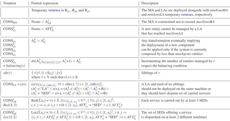
Figure 1 offers a visual example of how a configuration of DIET may look like, with and without an OMNI. For ob-vious clarity concerns, the naming service will not be repre-sented in future figures.
All instances of an architectural style are NOT created equal. At a given time, even though a configuration meets all the requirements of the application, another configuration may meet them in a “better way”. In particular, we consider the following criteria :
6 http://www.sysfera.com/sysfera-ds.html
Fig. 1 Logical view of a DIET configuration, with and without an OMNI
– the energy consumption,
– the robustness, i.e. the fault-tolerancewith regard tothe
breakdown of a machine or a software component, and – the quality of service.
We assume that the energy consumption depends only on the number of used machines and of the software com-ponents deployed on them.
The robustness, instead, is assessed based on three criteria that refers to the set of SEDs running the same service: (i) redundancy degree; (ii) location; (iii) balance within the hi-erarchical structure. For example, even if multiple SEDs are used for the same service (i.e., redundancy) it is important to allocate them on different machines (i.e., location) to re-duce the vulnerability to hardware breakdowns. Similarly, spreading the SEDs far apart within the system tree helps improving the resiliency to LA failures (subject to the con-straint that the LAs, not belonging to the same path from the MA to a SED, run on different machines).
Regarding quality of service, the load balance among the different vertice at the same depth in the tree is considered as criterion. Let LA(d) be the set of LA of depth d, and M(c) be the number of entities managed by the component c. An
en-tity can be deployed and directly managed by a LA∈ LA(d)
if it does not make the standard deviation ofSla∈LA(d)M(la)
become greater than a target threshold value, noted maxσ.
An interesting point here is that robustness and energy con-sumption are concurrent, in the sense that deploying more software components or using more machines will, while
Table 1 Main Notations for the DIET use-case. Notation Meaning
LA(d) the set of LA of depth d
M(c) the number of entities managed by the component c
maxSonsMA the maximum number of entities managed
maxSonsLA by the MA or a LA, respectively
minSonsMA the minimum number of entities managed
minSonsLA by the MA or a LA, respectively maxσ threshold value of the balancing condition
ameliorating the first, badly impact the second.
To value these three objectives, it is crucial to keep track of some attributes of the software components :
1. the depth of each LA,
2. the number of entities managed by each component c of type LA and MA : M(c),
3. the set of services carried out by each SED and LA, 4. the machine on which each entity is deployed.
Notations introduced to describe DIET are summarized in Table 1.
3.2 Problem Statement
Herein we illustrate the main issues in modelling the DIET architecture using classical approaches:
3.2.1 Interdependency of attributes
The attributes of an entity v may depend on attributes be-longing to a set S of other entities. In classical string gram-mars, attributes are classified as inherited or synthesized de-pending on whether the elements of S are parents/siblings of
vin the parse tree or not, respectively. The value of
synthe-sized attributes cannot be known in the context where they
first appear. They depend on following application of
pro-duction rules.In graph grammars, these rules traditionally symbolize the addition of software components. Similarly, graph attributes have to be handled in a very different way whether they only depend on attributes belonging to already existing entities or not. The first case can easily be addressed with attributes inheritance in graph grammars. For example, the depth of an LA could easily be derived from the depth of the entity managing it.
This does not apply in the second case. In fact, the set of services offered by an LA, for example, cannot be known in advance since they depends on children nodes that will be
added or striped later on.There exist two potential solutions
to this problem. Firstly, the attribute may be defined through
its analytic expression. This last is either evaluated on de-mand or systematically re-evaluated after each transforma-tion. Such an evaluation can be time consuming. It may also be unnecessary, for example when the attribute value has not changed. Furthermore, evaluation after each graph transfor-mation is not to be taken lightly. These lasts are not only ap-plied in a deployment step. They also characterize dynamic evolution of the system. Secondly, the attribute may be di-rectly associated to its value and updated when necessary. This last solution is directly related to the modification of an existing attribute discussed in the next sub-subsection. 3.2.2 Modification of an existing attribute
As discussed in 2.2.2,classical approaches allow a graph
rewriting rule to modify attributes within its scope only. When considering interdependency of attributes, a modification has to be propagated to dependant attributes. This may lead to a vast number of rule applications. For example, when de-ploying a SeD on a LA, its set of carried out services have to be updated accordingly. In fact, this update has to be recur-sively impacted on the ancestor of the updated entity until reaching the MA or a LA that already did carried out each services provided by the new SeD. In this scenario, there are as many rule applications as modified LAs. This phenomena leads to a loss of efficiency and scalability.
3.2.3 Configuration evaluation: handling constraints Soft and hard constraints can be used to reflect functional and non-functional requirements of a system. Their fulfil-ment or dissatisfaction enable configuration evaluation.
It is crucial to make the distinction between integrat-ing constraints within the architectural style, buildintegrat-ing a con-strained style, and restraining the architectural style. Exist-ing graph-based approaches are often restricted to the sec-ond case, where constraints are used to narrow the scope of correctness only. They are integrated to the model of the style, e.g. to the type graph in [5], but not in the configura-tions themselves.
These constraints, closely related to the system and its components, are similar to attributes; they depend on at-tributes, are evolving, and components of the same type have analogous requirements. Hence, their integration in the model as any attributes is relevant. In particular,we wish, while constructing, deploying, or reconfiguring a configuration, to construct an easily evaluable set of constraints. Their viola-tion could be detected and automatically handled by a man-ager without requiring complex decision and without
ana-lyzing the whole application.Firstly, approaches from the
literature consider unknown and variable attribute in rules only, but discard their existence from a graph. Thus, classi-cal constraints do not handle such attributes. Secondly, con-straints are tackled by post-condition checking or evaluated
after each rule application. Each constraints is then evalu-ated after a graph transformation even though it may not be changed. This concern is very similar to attribute interde-pendency.
These three points put under the spotlight the limits of classical graph-based formalism and the need for its expan-sion described in this paper.
4 Introducing Constraints and Mutators within Graph Rewriting Systems
4.1 Attributes, Constraints and Attributes Rewriting 4.1.1 Attributes
The proposed formalism conserves the simplicity and the computational efficiency of “listing” attributes as labels [32]
while granting the possibility offlexibly applying algebraic
operators.An attribute is represented as a couple, whose first
elementrepresents its value.The second element is its
do-main of definition. We assume the canonic notation where
YXis the set of function from X to Y.An interval of integer
is noted[a..b].
Definition 1 (Attribute) An attribute is a couple Att = (AttA,
AttD) where
– AttAis called value and is either
– a variablein AttD,
– a constant or
– an expression of a (S, OP)-algebra [12], where (S,
OP) is an infinite algebraic signature with S a set of sorts including AttD and OP a set of function
sym-bols such as OP = (AttD)S
+
.
– and AttDis its domain of definition.
An attributed structure or system is a couple composed of the structure and a set of indexed attributes or sequence
of attributes.By convention,the first member of an attribute
will be noted within quotation marks if and only ifits current
value is a constant. 4.1.2 Constraints
Attributes are entirely aimed at providing information on an algebraic structure. Constraints can be seen as a specific
kind of attributes.
Definition 2 (Constraint) A constraint Cons is an attribute
(ConsC, ConsD) with ConsD={“true”, “false”, “unknown”}.
Considering that constraints share the same domain of
definition, it will be implicit from now on. Aconstraint Cons
= (ConsC, ConsD) may be simply referred to as ConsC. In the
following, the principles of Kleene’s strong logic [24, 25]
are adopted, in particular its basic logic operations (∨, ∧, ¬,⇒) and the fact that the only truth value is “true”. The unique-ness of this truth value means that evaluations are pessimistic, i.e. “unknown” is supposed to be false.
Remark 1 A constraint can be seen as a classical expres-sion of a predicate ternary logic. Considering a ternary logic rather than a binary one implies that unlike attributes, con-straints can always be evaluated. Any minimal logic expres-sion that can not be evaluated, due for example to an at-tribute implied in its expression being un-evaluable or vari-able, is “unknown”.
In order to lighten the notation, an attributedobjectwith
constraints, i.e. a triple composed by theobject, a set of
in-dexed attributes,and a set of indexed constraints,is called
an AC-objector structure. Whenever defining an AC-object
containing AC-objects, rather than separating each sets of
attributes (resp. constraints), a single family of sequence of attributes (resp. constraints) indexed by the sets of attributed (resp. constrained) elements is considered.
Definition 3 (AC-object) An object ob j alongside a set of attributes ATT and constraints CONS is called an AC-object and noted (ob j, ATT, CONS).
4.1.3 Attributes Rewriting
One of the issues evoked in section 3 is the fact that at-tributes are prone to evolve. A reconfiguration may thus im-pact the attributes of the system, the addition of a SED may for example modify the set of services carried out by some LAs. In the literature, classical string rewriting theory [31] tackles this issue by using mutators. A similar approach is adopted here.
Definition 4 (A mutator on an AC-object) A mutator on
an AC-objectis an arbitrary algorithm updating the value(s)
of none, one or someof its attributes and constraints.
According to this definition, the scope of mutators re-mains limited to modification of values. They can not be used neither to add or suppress an attribute nor to modify the domain of definition of an attribute.
4.2 Attributed Constrained Graph Modelling a Configuration
4.2.1 Definition
An AC-graph,modelinga software snapshot or
ofvertexesand edges where an edge is a couple ofvertexes (source, destination). Following the commonly used conven-tions for standard graphical descripconven-tions, one considers that vertexesrepresent services or architectural components and edges correspond to their related interdependencies. Note thatvertexes, edges and the graph itself are AC-systems. For
any set S, the cardinality of S is represented as|S|.
Definition 5 (AC-graph) An AC-graph is defined by the system G = (V, E, ATT, CONS) where
– V and E⊆ V2correspond to the set ofvertexesand edges
of the graph respectively,
– ATT (resp. CONS) is a family of sets ATTel(resp.
CONSel), where el isa vertex, an edge or the graph
itself. Consequently, ATT (resp. CONS) is indexed by a
subset of V∪ E ∪ {G}. ATTelis a set of attributes (resp.
constraints) of arbitrary length and containing the
sequence of attributes (ATTi
el= (Aiel, Diel))i∈[1..|ATTel|]
(resp. (CONSiel= (Ciel, Diel) )i∈[1..|CONSel|]) of the
element el.
– For any attributes (Ai
el, Diel), Aielis a constant, a variable
or an expression of a (S,OPel,i)-algebra where S = S e∈{ ˜e:AT Te∈AT T } S j∈[1..|AT Te|]D j eand OPel,i= (Diel)S + . For any graph (V, E, ATT, CONS), an element el∈ V ∪ E is said to be attributed (res. constrained) if ATTel∈ ATT.The
graph is partially attributed and constrained since ATT and
CONS are indexed by a subset of V∪ E ∪ {G}. In this way,
an empty set of attributes or constraint is not required if an element is wished not to be attributed or constrained.
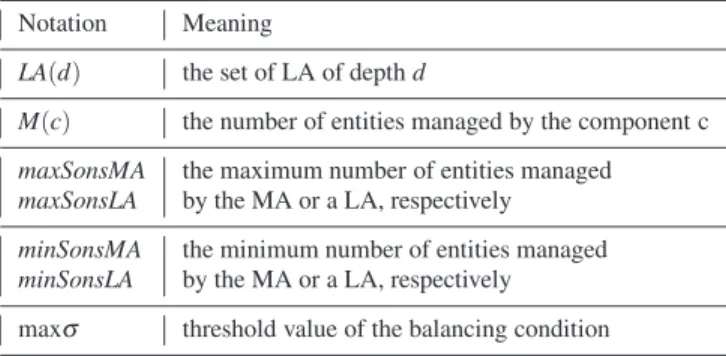
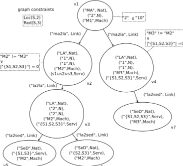
Now that AC-graphs are defined, it is possible to repre-sent a configuration of DIET as prerepre-sented in section 3. 4.2.2 Modelling a Constrained Configuration of DIET This subsection is dedicated to the definition of a DIET con-figuration. Concerns expressed in Sec.3 are mapped into the theoretical concepts previously introduced in this Section. For sake of clarity, before formally introducing architec-tural styles, we show in Figure 2 what a DIET configuration would look like, once represented using an AC-graph. Notations are reported in Table 2.
In the case of a DIET architecture :
– Nat, the set of possible natures of a software component,
is equal to{“OMNI”, “MA”, “LA”, “SED”} .
– Link, the set of possible relationships between entities, equals
{“ma2la”, “ma2sed”, “la2sed”, “la2la”, “registered”}
Redand Loc, the redundancy and constraints, are further
de-scribed in the dedicated paragraph.
Fig. 2 An AC-graphmodelinga configuration of DIET
Table 2 Notations used to describe a DIET configuration (see Fig. 2) Notation Meaning
Mach the set of available machines
Nat the set of possible natures of a software component
Link the set of possible relationships
S the set of services that could be carried out by a SED
Serv the power set of S
Red the redudancy constraint
Loc the localisation constraint
Description of the configuration At this time, the software
is composed by eight components symbolized by eight
ver-texesand theirs corresponding relationsmodeledby some edges, both attributed to reflect their properties and natures. A notable fact is that components of the same nature have the same number of attributes, theirs attributes being the one identified in Sect. 3. This is ensured by the definition of the rewriting system that will be presented later in this paper. Some components as well as the graph itself are constrained to reflect the concerns stated in the same section.
Constraints are represented within doted frames, and
re-lated to theirtargeted objectby a doted line, except for those
linked to the graph itself.
Attributes The first attributes of each vertex states the nature
of themodeledentity, in Nat. The configuration comprises
a MA managing 2 entities and deployed on a machine noted
m1, as represented by its second and third attribute,
Each LA possesses three more attributes, related to its depth, the number of entities it managed, the machine it is deployed on and its provided set of services. In the example, three LAs
are deployed, represented by v2, v3and v4, of depth 1, 1 and
2, managing 2, 1 and 2 entities, and placed on machine m2,
m3and m4, respectively. The first one, v3, manages directly
or indirectly SEDs providing the set of services s1∪ s2∪ s3,
the second one, v4, provides s4and v5, the third one, s1∪
s2.
Finally, four SEDs deployed on m5, m6, m7 and m8 carry
out the services s1, s2, s3and s4.
Note that machines and proposed services are represented by variable, and their actual value is not currently know.
Constraints The MA should not manage more that 10 enti-ties, underlining a fundamental property of the architectural style. Load balancing is not represented since it is tackled by conditional deployment, as stated previously.
To cope with robustness, the graph is constrained by two clauses Loc(S,2) and Red(S,3), taking into account the needs for redundancy and multiple locations over the offered ser-vices.
∀ ¯S⊆ S, ∀xs∈ N , let the redundancy constraint Red( ¯S,xs) be
“There are at least xsSEDs carrying each service s in ¯S”.
Red( ¯S,xs) =∀s ∈ ¯S, ∃(vi)i∈[1..xs]∈ V xs, (∀(i, j) ∈[1..x s]2, i6= j⇒ vi6= vj)∧ (∀k ∈[1..xs], ATT1vk = “SED”∧ s ∈ AT T 2 vk).
∀s ∈ ¯S, ∀xs∈ N , let the location constraint Loc( ¯S,xs) be
“For each service in ¯S, there are at least xs different
ma-chines on which at least a SED carrying out the service s is deployed”. Loc( ¯S,xs) = ∀s ∈ ¯S, ∃(vi)i∈[1..xs] ∈ V xs, ( ∀(i, j) ∈ [1..x s]2, i6= j ⇒ (vi6= vj∧ AT TV3i6= AT T 3 Vj)) ∧ (∀k ∈[1..xs], AT T 1 vk= “SED”∧s ∈ AT T2 Vk.
This means that each service should be carried out by at least 3 SEDs located on at least two different machines.
In addition, a notion of location balance within sub-trees is introduced to re-enforce robustness. It is specified that a LA and a component managed by the same entity should not be deployed on the same machine or that they should have disjoint set of carried services. This constraint avoids, within a sub-tree, that SED providing similar services, and deployed in different location thanks to the clause Loc, are managed by entities deployed on the same machine. Hence the number of devices that have to breakdown in order for a service to be disrupted is increased.
Formal definition The graph in the Fig. 2 is defined as fol-low.
G = (V, E, ATT, CONS) where V ={v1, v2,. . ., v8},
E ={ e1= (v1, v2), e2= (v1, v3), e3= (v2, v4), e4= (v2, v7),
e5= (v3, v8), e6= (v4, v5), e7= (v4, v6)},
ATT ={ATTG, ATTv1, ATTv2,. . ., ATTe8},
ATTv1={(“MA”, Nat), (“2”, N), (m1,Mach)}.
ATTv2 ={(“LA”, Nat), (“1”, N), (“2”, N), (m2, Mach), (s1∪
s2∪ s3, Serv)},
ATTv3 ={(“LA”, Nat), (“1”, N), (“1”, N), (m3, Mach), (s4,
Serv)},
ATTv4 ={(“LA”, Nat), (“2”, N), (“2”, N), (m4, Mach), (s1∪
s2, Serv)}.
ATTv5 ={(“SED”,Nat), (s1, Serv), (m5, Mach)},
ATTv6 ={(“SED”,Nat), (s2, Serv), (m6, Mach)},
ATTv7 ={(“SED”,Nat), (s3, Serv), (m7, Mach)},
ATTv8 ={(“SED”,Nat), (s4, Serv), (m8, Mach)}.
CONS ={CONSG, CONSv1, CONSv2, CONSv3, CONSv4},
CONSG={Loc(S,2), Red(S,3)},
CONSv1 ={ATT 2 v1≤ 10}, CONSv2 ={ATT 4 v26= ATT 4 v3 ∨ (ATT 5 v2∩ ATT 5 v3 = /0)}, CONSv3 ={ATT 4 v36= ATT 4 v2 ∨ (ATT 5 v3∩ ATT 5 v2 = /0)} and CONSv4 ={ATT 4 v46= ATT 3 v7 ∨ (ATT 5 v4∩ ATT 2 v7 = /0)}.
From now on, notions allowing to characterize the cor-responding architectural style are introduced, ensuring in particular that attributes are correctly updated and that com-ponents have the required constraints.
4.3 Graph Rewriting Rules and Grammars
An architectural style can beformalizedusing a graph
gram-mar. The production rules of such systems require to iden-tify sub-structures by the means of homomorphisms. An
un-attributed graph homomorphismh between two graphs is
defined as an injective function f from the set ofvertexes
of the first one to the set ofvertexesof the second graph
so that if there is an edge between twovertexesof the first
one there is an edge between their image in the second one. By notational abuse, the image of a vertex v by f is noted h(v), the image of an edge (v, v′) is noted h((v, v′)) instead of( f (v), f (v′)), and the image of a subgraph ˜G= ( ˜V, ˜E) of
Gis noted h( ˜G).
To tackle attributes, we impose firstly that twovertexes
or two edges associated throughahomomorphism have the
same number of attributes. Attributes of two associated ele-ments are themselves correlated with regard to the order of their occurrences. Identified attributes should have the same
domain of definition. Secondly, identifications of attributes should be consistent, e.g. a variable should not be identified with two different constants. Therefore, a system of equa-tions is built and the existence of an attributed induced sub-graph isomorphism is conditioned by its resolvability. Definition 6 (AC-graph homomorphism)
A homomorphism between two AC-graphs G = (V, E, ATT,
CONS) and G’ = (V’, E’, ATT’, CONS’), noted G→G’,is a
homomorphism h from (V, E) to (V’, E’) such as 1. ∀ el ∈ V ∪ E, |ATTel| = |ATTh(el)|.
2. ∀ el ∈ V ∪ E, ∀ i ∈ [1..|ATTel|], Diel= Dih(el).
3. The system of equations S ={ A = A’:
∃ el ∈ V ∪ E, ∃ i ∈ [1..|ATTv|], A = Aiel∧ A’ = Aih(el)}
has at least one solution. Remark 2
– Constraints do notimpact thedefinition ofa
homomor-phism. It will be shown that they intervene in the rewrit-ing process in a different way. Similarly, attributes on vertexesand edges are the only one that are considered whereas attributes on the graph itself are not.
– The existence ofahomomorphism is conditioned by the
resolvability of a system of equations on attributes. As stated in the introduction, in attributed graphs [19, 12], the existence of a morphism is also conditioned by equal-ities between attributes, potentially through morphism between attributes spaces. However, this is often the only clause relying on attributes that impact the applicability of a graph rewriting rule.
Solving the system of equations S results in identifying the value of some attributes with some constants in their do-mains of definitions and/or with the value of some other at-tributes. Integrating the affectation obtained by solving the systems refers to the update of the value of the attribute to reflect these identifications. For example, if ((x,y), (x,“2”))
∈ S2, meaning that x has been identified to the variable y
and the constant “2”, integrating the affectation obtained by solving S will lead to replacing each occurrence of x and y by “2”.
There exists a vast number of approaches handling graph rewriting based on attributed graphs [19, 12]. Their applica-bility depends on various factors, always including the
exis-tence ofahomomorphism between an element of the graph
rewriting rule and the graph to rewrite. Inspired by string grammar theory [31], these factors are expanded herein to include the satisfaction of a set of constraints on attributes, namely the set of constraints of the AC-rewriting rule.This potentially empty set can be seen as a set of semantic predi-cates.
Applying a rewriting rule on a graph consists in sup-pressing a part of the graph and extending it by adding some vertexesand edges. In addition to classical modifications in-duced by the application of a rule, a set of actions is
per-formed at the end of said application.For any AC-graph G
=(V, E, AT T,CONST ) and any of its subgraph ˜G= ( ˜V, ˜E, ˜
AT T,CONST˜ ), the notation G\ ˜Grefers to G deprived of ˜G,
i.e. the graph ¯G= ( ¯V, ¯E, ¯AT T,CONST¯ ) where : – ¯V = V\ ˜V,
– ¯E= E∩ ¯V2,
– AT T¯ ={AT Tel∈ AT T : el ∈ ¯V∪ ¯E} ∪AT TG,
– AT T¯ ={AT Tel∈ AT T : el ∈ ¯V∪ ¯E} ∪AT TG.
Virtually, any attributed graph rewriting formalism could be extended to include semantic predicates, constraints and mu-tators. In order to fix the idea, the classical double push out formalism defined in [34] has been chosen, alongside with the attribute management presented previously.
Definition 7 (AC-rewriting rule of AC-graph) An AC rewriting rule of an AC graph is a 5-tuple (L, K, R, ATT, CONS, ACT) where
– ATT = ATTrule∪ ATTL∪ ATTRis a set of attributes,
ATTrulebeing the set of attributes of the graph rewriting
rule itself,
– CONS = CONSrule∪ CONSR\Kis a set of constraints,
CONSrulebeing the set of constraints of the graph
rewriting rule itself and CONSR\Kset of constraintson
ER\K∪VR\K,
– (L = (VL, EL), ATTL, /0) and (R = (VR, ER), ATTR,
CONSR\K) are AC-graphs,
– K = (VK, EK) is a sub-graph of both L and R,
– ACT is a set of actions.
A rule is applicable on a AC-graph G if :
1. there isahomomorphism h : (L, ATTL, CONSL)→ G,
implying in particular that the system of equations S ={
A = A’: (∃ v ∈ VL,∃ i ∈[1..|ATTv|], A = Aiv∧ A’ =
Aih(v))∨ (∃ e = ( ¯v, ˜v) ∈ E, ∃ i ∈[1..|ATTe|], A = Aie∧ A’
= Ai(h( ¯v),h( ˜v)))} has at least a solution,
2. the application of the rule would not lead to the appari-tion of any dangling edge,
3. each Cons∈ CONSruleis evaluated to “true” by
integrat-ing the affectations obtained by solvintegrat-ing S and by evalu-ating each elementary logic expression containing vari-able attributes to “unknown” as stated in remark 1. Its application consists in :
1. erasing h(L\K)including CONSh(L\K),
2. integrating the affectations obtained by solving S to the remaining graph,
3. adding an isomorph copy of R\K, including CONSR\K,
4. performing each action Act∈ ACT.
Graph rewriting rules treat vertex and edge constraints much like attributes. They are added and suppressed along-side the element they target.
Efficientaccess to attribute values: evaluation on demand or update on modification Note that, thanks to mutators, this formalism enforces several ways of considering and eval-uating attributes or constraints. These lasts can be explicitly characterized by their analytic expression. However, this ex-pression has to be calculated whenever its value is required or after each transformation. To avoid frequent evaluations, the attribute value can be stored and be updated whenever it has to be, using mutators. The choice between these two options rely on the relative complexities and frequencies of updates and evaluations.
Inspired from Chomsky’s generative grammars [10], graph grammars are defined as a classical grammar or rewrit-ing system, and formally characterize an architectural style. Definition 8 (Graph Grammar)A graph grammar is de-fined by the 4-tuple (AX, NT, T, P) where
– AX is the axiom, an AC-graph with a single vertex AX
– NT is a set of AC-vertexes, called non-terminal term of
the grammar,
– T is a set of AC-vertexesterminal term, named terminal
term of the grammar,
– P is the set of AC-rewriting rules, or production rules, belonging to the graph grammar.
Each vertex occurring in a graph rewriting rule in P or in a
graph obtained by applying a sequence of productions∈ P
to the axiom is then isomorph to at least one arch-vertex in
NT or T .
Terminal terms define archetype ofvertexeswith
corre-sponding pattern of attributes and constraints. On the other hand, production rules grant constraint management and sys-tem updates. Terminal terms and productions guarantee that each component, at any time, of the system is correctly con-strained and attributed according to its type.
Definition 9 (Instance belonging to the graph grammar)
An instance belonging to the graph grammar (AX, NT, T, P)
is a graph obtained by applying a sequence of productions in
Pto AX .If an instance does not contain any vertex isomorph
to an arch-vertex from NT it is said to be consistent. Correct-by-Construction Reconfigurations. Correct by con-struction reconfigurations based on the generative aspect of
graph grammars is one of theirs key advantages. A
trans-formation is considered correct if its application to an in-stance of the grammar produce another one. Productions of
the grammar are correct by definition. Thanks to operations on graph rewriting rules that preserve their correctness, cor-rect transformations can be built starting from productions rules. Applicability restriction, for example, is such an oper-ator.
Let r be a rewriting rule whose application is equiva-lent to the application of a production p. It is immediate that r preserves consistency if its applicability conditions are
equivalenttoor stronger than those of p, e.g. if r requires a
larger pattern to be found meaning that Lris a sub-graph of
Lp.This still holds in presence of mutators and constraints. In addition to classical requirements, the application of two rules is equivalent if they have the same mutators. If the ap-plication conditions of a rule are stronger than those of a rule p, they still are if the first is as least as constrained as the second, e.g. if CONSp⊆ CONSr.
4.4 Summary of the Proposed Contribution
In the previous Sub-Sections, a complete description of the proposed formalism has been detailed. Here, for sake of clar-ity, we highlight its pivotal features and advantages in a con-cise form.
– Attributes are enriched to cover their interdependencies and potentially unknown values. Their definition, rather than being restricted to predefined operators and depen-dencies, is based on the characterization of every admis-sible relationships.
– Constraints are defined as a special kind of attributes, so as to benefit from their evolution and dependencies mechanisms. Being elements of a ternary logic system, they cope with unknown attributes.
– Graph rewriting rules are expanded with the considera-tion of constraints and mutators. Firstly, constraints on the rule itself constitute semantic predicates that allow
decision making in presence of unknown attributes.
Con-straints are added and deleted alongside the element they target.Secondly, mutators, adapted from classical string theory, manage efficiently and flexibly attribute modifi-cations.
Accordingly, it is possible to extendgraph grammar ap-proaches in order to embrace these new features, capitalize their strengths, and enable the effective management of dy-namic software architectures subordinate to functional and non-functional requirements.
5 Exploitationand Illustrationof the New Formalism :
DIET Characterization, Evaluation and Management
This Section illustrates the potential of the elaborated for-malism by first describing DIET, taking into account each consideration introduced in Sect. 3. Then, the fitness of this description to appropriateness evaluation and performance aware management is demonstrated using concrete exam-ples.
5.1DIET Characterization.
This section is dedicated to the characterization of the DIET application described in Sect. 3 using the new formalism presented in this contribution. To this end, we design ax-ioms, terminal terms, and production rules of the Graph Gram-mar that unambiguously define DIET. Also, we formally demonstrate the termination of the resulting grammar. 5.1.1 Axiom
Considering the definition of graph rewriting rules and sys-tems, instances of the such systems are graphs that inherit the attributes and constraints of the axiomatic graph. In the case of DIET, attributes and constraints shared by all possi-ble software configurations are:
1. the largest number of entities that a LA may manage (the minimum being directly granted by production rules), 2. the largest number of entities that a MA may manage
(idem),
3. the threshold value intervening in the balancing condi-tion discussed in Sec. 3,
4. the maximum of total agents and 5. the current number of agents.
Common constraints, instead, refers to redundancy and lo-cation conditions each configuration has to satisfy.
Therefore, let AXDIETbe (vAX, ATTAX= ((maxSonsLA,
N), (maxSonsMA, N), (maxσ, R+), (maxAgents, N),
(curA-gents, N)), CONSAX = (Loc(S,2),Red(S,3))), where
curA-gents = 0 and, arbitrarily, maxSonsMA = maxSonsLA = 10 and maxAgents = 100.
Throughout this section, the graph on which production rules will be attempted to be applied to is noted G = (V, E, ATT, CONS). Attribute and constraint inheritance ensure that if G is an instance of the architectural style defined here,
ATTG= ATTAXand CONSG⊆ CONSAX.
5.1.2 Terminal Terms
These terms characterize types of AC-vertexes, defining a
pattern of attributes and constraints shared by vertexesof
the same kind.
The naming system itself is not constrained, and its at-tributes are limited to its nature and the machine it is
de-ployed on. Therefore, let TOmnibe (vOmni, ATTOmni= ((“Omni”,
Nat), (m, Mach)), /0).
Similarly, let TSED = (vSeD, ATTSED = ((“SED”, Nat), (s,
Serv), (m, Mach)), /0).
The MA shall not manage more than 10 entities.
Accord-ingly, let TMAbe (vMA, ATTMA= ((“MA”, Nat), (Nsons, N),
(m, Mach)), CONSMA= ((Nsons< A2AX))).
Finally, a LA and a component managed by the same entity should not be deployed on the same machine or they
should have disjoint set of carried services. Let ˆvbe the
en-tity managing v, i.e. ˆv∈ V such that ( ˆv,v) ∈ E, and sib(v) =
{ ¯v:( ˆv, ¯v) ∈EG} \{v} the set of components managed by ˆv,
excluding v, i.e. the siblings of v.
TLAis (vLA, ATTLA= ((“LA”, Nat), (depth, N), (Nsons, N),
(m, Mach), (s, Serv)), CONSLA= (c(vLA)), where
c(v) = (c(v)i)i∈[1..|sib(v)|],∀ ˜v ∈ sib(v), !∃ i ∈[1..|sib(v)|],
(Av1= “LA”∧ c(v)i= (A4v6= Av4˜)∨ (A5v∩ A5v˜= /0))∨
(A1
v= “SED”∧ c(v)i= (A4v6= Av2˜)∨ (A5v∩ A3v˜= /0))
5.1.3 Productions of the Grammar
Production rules of the graph grammar formalize the con-struction of its instances by defining when and how an entity may be deployed and the consequences of such a deploy-ment.
The first rule (p1) to define is theinitialization
consum-ing the axiomatic vertex (Del). The namconsum-ing service and the MA are deployed, as well as a non-terminal vertex granting that the MA manages at least an entity (Add). This vertex will be later on instantiated into a LA or a SED. Finally, the MA registers to the naming service and the current number of agents is updated accordingly.
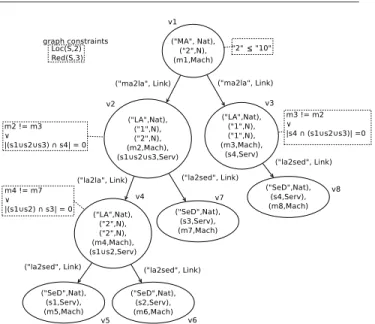
Let p1= (Lp1, Kp1, Rp1, /0, /0,µregistering(pv2),µinc(G, 5, 3)
), whereµregistering(v) is the action of registering the object
represented by the vertex v to the naming service.µinc(e, i,
1), defined in Fig. 3, represent the incrementation of the i-th attribute of v by n.
Graphical parts of the rewriting rules are illustrated here us-ing the format L←K→R. This graphical representation is
illustrated in Fig. 4, where Lp1, Kp1, Rp1 and pv2 are
de-fined.
Productions rules p2and p3model the addition of a
non-terminal vertex, managed by the MA or a LA, respectively. This temporary vertex will later on be instantiated into a LA or a SED. To deploy a new entity, three condition should be
µinc(e, i, n)
Ai
v← Aiv+ n
Fig. 3 µinc(v, i, n), Incrementation of the i-th attribute of the element e
by n
Fig. 4 Initialisation
Fig. 5 Addition of a non-terminal term
met. This addition should respect (1) the balancing condi-tion, (2) the maximal number of agents manageable by its superior and (3) the maximum number of total agents. The application of these productions leads to the incrementation of the numbers of total agents and of sons of the entity man-aging the added vertex.
Let p2= (Lp2, Kp2, Rp2, /0, A
4
G> A5G, (µinc(pv2MA, 2, 1),
µinc(G, 5, 1))) and
p3= (Lp3, Kp3, Rp3, /0, (balancing(pv2LA), Nsons< ATT
1
G, A4G> A5
G), (µinc(pv2LA, 3, 1),µinc(G, 5, 1)),
where Lp2, Kp2, Rp2, pv2LA, Lp3, Kp3, Rp3, and pv2MA are
defined in Fig. 5. balancing(v) =σ((A3la)la∈LA(A2
v)\{v}, A
3
v+1) < A3
G, whereσ(s) is the standard deviation of the sequence
s.
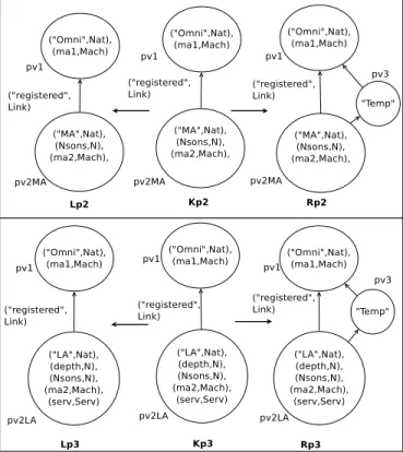
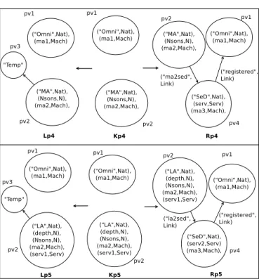
The instantiation of a temporary vertex managed by the
MA or a LA into a SED is described by p4and p5,
respec-tively. After deploying the SED, it has to register to the nam-ing service and, if it is managed by a LA, update the set
of its carried out services. Let p4 = (Lp4, Kp4, Rp4, /0, /0,
µregistering(pv4)) and p5= (Lp5, Kp5, Rp5, /0, /0, (µregistering(pv4),
µupdateServ(pv2,pv4,2)), where Lp4, Kp4, Rp4, Lp5, Kp5, Rp5,
pv2, and pv4 are defined in Fig. 7.µupdateServ(v, ˜v, ind),
de-scribed in Fig. 6, impact a change in Aindv˜ , the set of carried
out services by ˜v, on v, the component managing ˜v, by
updat-ing the set of services it proposes. This update is conducted only if v is a LA, and, if there is indeed a change, it is prop-agated to the entity managing v.
µupdateServ(v,v, ind)˜ if A1 v= “LA” oldServ← A5 v A5 v← oldServ ∪ Aindv˜ if A5 v6= oldServ ¯ v← ˆv ∈ VG, ( ˆv, v)∈ VE µupdateServ( ¯v, v)
Fig. 6 µupdateServ(v, ˜v, ind), A change of Aindv˜ , the set of services
car-ried out by ˜v, impacts v, the entity it is managed by.
The two last productions of the grammar, p6and p7,
de-scribe the instantiation of non-terminal term into a LA man-aged by the MA and a LA, respectively. Since a LA has to manage at least one entity, such an instantiation can be con-ducted only if an entity can be later on deployed without
ex-ceeding the maximum number of agents. Let p6= (Lp6, Kp6,
Rp6, /0, A
4
G> A5G, (µregistering(pv4),µinc(G, 5, 1))) and p7=
(Lp7, Kp7, Rp7, /0, A
4
G> A5G, (µregistering(pv4),µinc(G, 5, 1))),
where Lp6, Kp6, Rp6, Lp7, Kp7, Rp7, and pv4 are defined in
Fig. 8.
5.1.4 The Constrained Attributed Graph Grammar Characterizing DIET
Considering the sets introduced in this section, GRSDIET,
the graph rewriting system formally characterizing DIET,
introduced in Sect. 3, is defined as GRSDIET =(AXDIET,
NTDIET, TDIET, PDIET), where
Fig. 7 Instantiation of a non-terminal term into a SED
Fig. 8 Instantiation of a non-terminal term into a LA
= /0),
TDIET ={ TOmni, TMA, TLA, TSED}, and
PDIET ={ p1, p2, p3, p4, p5, p6, p7}.
Note that the limitation of entities that can be managed by the MA or a LA are not tackled in the same way. A
con-straint reflecting this restriction is added on the MA, whereas the satisfaction of this limitation is granted for the LAs by a semantic predicate. Said predicate restricts the
applicabil-ity of p3by imposing, before making a LA manage a new
component, that said LA as not reach the limit of
compo-nent it can manage. Since p3 is the only production of the
grammar increasing the number of entities managed by a LA, this limit can not be overpassed. A brief summary of the mapping between the concerns expressed in Sec. 3 and formal concepts is presented in Table 3.
Loc(S,2),Red(S,3)
∀s ∈ ¯S, ∀xs∈ N , let the location constraint Loc( ¯S,xs) be
“For each service in ¯S, there are at least xs different
ma-chines on which at least a SED carrying out the service s is deployed”. Loc( ¯S,xs) = ∀s ∈ ¯S, ∃(vi)i∈[1..xs]∈ V xs, ( ∀(i, j) ∈[1..x s]2, i6= j ⇒ (vi 6= vj∧ AT TV3i 6= AT T 3 Vj) ∧ (∀k ∈[1..xs], AT T 1 vk = “SED”∧s ∈ AT T2 Vk.
Guaranteeing theoretical properties of the grammar: Termi-nation. A generative grammar is said to be terminating if there can not be an infinite sequence of its production rules. Theoretically, this property ensures that the set of instances of the grammar is finite and that its exploration or the con-struction of an instance can be represented by a terminat-ing algorithm. Practically, this property is consistent with the finiteness of the available resources, like machines and theirs computing powers.
Theorem 1 GRSDIET is terminating.
Proof Let S be a non-empty sequence of elements in PDIET
and|S| its size. Let’s prove that ∃ N ∈ N, |S| ≤ N.
For p∈ PDIET, let Occ(p) be the number of occurrences
of p in Sp. Accordingly,
|S| =Σp∈PDIETOcc(p). (1)
Let’s consider the following system of tokens :
– Token A : G4- G5, the number of agents that still can be
deployed.
– Token B : the number of temporaryvertexesin the graph.
Applying p2, p3, p6or p7decrease the number of token
A by 1, whereas p1requires 3. Hence,
3∗ Occ(p1) + Occ(p2) + Occ(p3)+
Occ(p6) + Occ(p7) ≤ maxAgents.
(2)
The application of p4or p5consumes 1 token B, whose
Table 3 Informal considerations and their formal translation
Notation Formal expression Description
Temporaryvertexesin Rp1, Rp6and Rp7 The MA and LAs are deployed alongside with minSonsMA
and minSonsLA temporaryvertexes, respectively
CONSMA Nsons< A2AX The MA is constrained not to exceed maxSonsMA
CONS2
p3 Nsons< ATT 1
G A new entity cannot be managed by a LA
that has reached maxSonsLA
CONSp2 A
4
G> A5G Any transformation eventually implying
CONS3
p3 the deployment of a new component
CONSp6 can be applied only if the system is currently
CONSp7 composed by less than maxAgents entities
CONS1p3 σ ((A 3 la)la∈LA(A2
v)\{v}, A 3
v+1)< A3G Incrementing the number of entities managed by v
= balancing(v) respect the balancing condition
sib(v) { ¯v:( ˆv, ¯v) ∈EG} \{v} Siblings of v
where ˆv∈ V such that ( ˆv,v) ∈ E
CONSLA= c(v) (c(v)i)i∈[1..|sib(v)|],∀ ˜v ∈ sib(v), !∃ i ∈[1..|sib(v)|], A LA and each of its siblings
(A1
v= “LA”∧ c(v)i= (A4v6= A4v˜)∨ (A5v∩ A5v˜= /0))∨ should not be deployed on the same machine or (Av1= “SED”∧ c(v)i= (A4v6= Av2˜)∨ (A5v∩ A3v˜= /0)) they should have disjoint set of carried services CONS1AX Red( ¯S,xs) =∀s ∈ ¯S, ∃(vi)i∈[1..xs]∈ V
xs, (∀(i, j) ∈[1..x
s]2, Each service is carried out by at least 3 SEDs Red(S, 3) i6= j ⇒ vi6= vj)∧ (∀k ∈[1..xs], ATT1vk = “SED”∧ s ∈ AT T
2 vk)
CONS2
AX Loc( ¯S,xs) =∀s ∈ ¯S, ∃(vi)i∈[1..xs]∈ V
xs, (∀(i, j) ∈[1..x
s]2, i6= j ⇒ The set of SEDs offering a service Loc(S, 2) (vi6= vj∧ AT TV3i6= AT T 3 Vj)) ∧ (∀k ∈[1..xs], AT T 1 vk = “SED”∧s ∈ AT T 2
Vk is dispatched on at least 2 different machines
Occ(p4) + Occ(p5) ≤ Occ(p1) + Occ(p2) + Occ(p3). (3)
Since p1consumes the axiom, it is obvious that
Occ(p1) = 1. (4)
Equation (2) thus becomes :
Occ(p2) + Occ(p3) + Occ(p6) + Occ(p7) ≤ maxAgents − 3.
(5)
By definition,∀ p ∈ PDIET, Occ(p)≥ 0. Accordingly,
equations (3), (4) and (5) give
Occ(p4) + Occ(p5) ≤ maxAgents − 2. (6)
According to equation (1),
|S| = Occ(p1) + (Occ(p2) + Occ(p3) + Occ(p6) + Occ(p7)) +
(Occ(p4) + Occ(p5)).
Thanks to equations (4), (5) and (6), this translates into |S| ≤ 1 + (maxAgents - 3) + (maxAgents - 2).
Finally,|S| ≤ 2*maxAgents-4. With maxAgents = 100,
we have|S| ≤ 196.
QED.
5.2 Appropriateness Evaluation
To enable the evaluation of DIET configurations, constraints are herein assigned a, potentially infinite, weight. In this way, the appropriateness of a configuration is reflected by calculating its opposite, i.e. the configuration cost. Said cost is calculated as the sum of the costs of its energy
consump-tionand of the violated constraints. The violation of a
con-straint in a configuration implies that every defined criteria is not respected. In this case, the configuration is not robust enough and its cost is therefore increased depending on the weight of the violated constraint. A configuration of infinite weight is considered incorrect, so that strong constraints are still enforced.
Notations Let ξ be the function of evaluation; ∀ cons ∈
CONS,∀ c ∈ cons,ξ(c) = 1 if c is “true” and 0 else.
Energy Consumption In Sec. 3, it has been presumed that energy consumption depends on the used machines and the number of deployed components only. In the following, this relation is (realistically according to [7]) assumed to be
lin-ear, and weighted byλmachandλentityfor used machine and
deployed component, respectively. Note that the number of current deployed component is already an attribute of the graph. For an easier evaluation, the number of used ma-chines can be added as attribute of the graph as well, and updated whenever necessary, i.e. when applying production
p1, p4, p5, p6or p7. The energy consumed by a configuration
is then:λmach· A5G+λentity· |V |.
Constraint violations It is clear that the constraint reflecting the limitation on the number of entities managed by the MA should not be violated and therefore has an infinite weight. Constraints reflecting the robustness of the system are, how-ever “soft” and are given arbitrary finite weight. The cost of violating the constraint stating that “a LA and a compo-nent managed by the same entity should not be deployed on the same machine or they should have disjoint set of carried services”, c(v), is weighted by the depth of the LA.
Redun-dancy and location constraints are weighted byλRandλL
respectively.
The cost related to the violation of constraints is :
λLξ(CONS1G) +λRξ(CONS2G) + λMAΣma∈V,A1 ma=“MA”ξ(CONS 1 ma) + Σla∈V,A1 la=“LA”λLA(A 2 laξ(CONS1la).
Part of the configuration illustrated in Fig. 2 is arbitrarily instantiated to be totally evaluable and presented in Fig. 9. S, the set of services that may be carried out by a SED, is {S1, S2, S3}.
Fig. 9 Instantiated AC-graph modelling a configuration of DIET
This configuration does not meet the redundancy con-straint, since there are only two SEDs that can carry out the services S1 and S2. Hence, its cost is equal to its energy
con-sumption plus the cost of violating said constraint: 3λmach+
7λentity+λR.
This natural and immediate way to deal with soft and hard requirements derives from the new formalism proposed in this paper. In fact, the model has been explicitly con-ceived to embed constraints, that may assume the role of performance indicator, and their admissible soft bounds by means of attributes. In this way, once the software archi-tecture properly described, its appropriateness can be easily evaluated on a dynamical basis.
5.3Non-Functional Requirements and Software Management
Thanks to the eased manipulation of system attributes and constraints, the introduced formalism can be fruitfully
ex-ploited in software management systems. Semantic
predi-cates and restrictions on rules’ applicability grant more flex-ibility on transformations, allowing to face specific aims on the fly.
Remark 3 Considering a new rule resulting of the restriction
of another can ensure guarantees with regard to the preserva-tion of the architectural style. However, it is worth noticing that properties of the graph rewriting system, e.g. conflu-ence, are not necessarily invariant with regard to the addition of a new rule.
Let’s consider the DIET configuration previously eval-uated (see Fig. 9). In this case, we can suppose that a SED is to be deployed to meet the redundancy constraint and im-prove the quality of the configuration.
The first thing to do is to apply p2, and by doing so
choosing the component that will manage the SED. To find an optimum solution, one should consider each possibility,
i.e. apply p2 on v2, v3 or v4, find in each case an optimal
solution, and then compare the costs of each solutions. Arbitrarily assumingthat p2has been applied on v2,an
op-timal solution can be found as follows.The temporary
ver-tex is to be instantiated into a SED using the production p5.
Since the motivation of this reconfiguration is to meet the
redundancy constraint, p5should be restricted in order for
its application to be relevant.
Firstly, the deployed SED should be able to provide the ser-vices S1 and S2. Assuming the notation introduced when
defining p5, see Fig.7,{S1, S2} ⊆ A2pv4.
Furthermore, the constraint (“M2” != A3
pv4)∨( “{S1,S2,S3}”
∩ A2
pv4= /0 ) will appear on v3. In order for this constraint to
be met, the transformation should verify that A3
pv46= “M2”.
Besides, for energy consumption reason and so as not to use
a new machine, it is imposed that A3pv4∈ {M1, M3}.
According to the style constraints, the graph presented in Fig. 10 is a possible optimal result of such a reconfiguration.
Every constraints are met and the cost of the configuration
is now limited to its energy consumption, 3λmach+ 8λentity.
Hence, this evolution is relevant if and only ifλentity<λR.
Fig. 10 A configuration satisfying every style-defined constraints
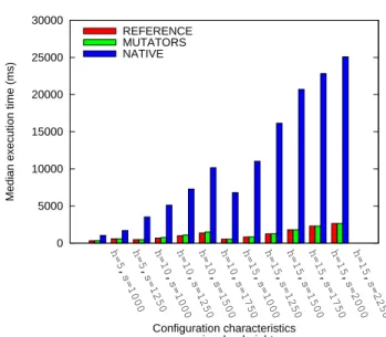
6 Experimentations : Efficiency Evaluation and Comparison
6.1 Experimental Background 6.1.1 Transformational Scenario
The transformation conducted in the experiments consists in the addition of a SeD on a LA of maximal depth. This transformation implies two attribute updates. Firstly, the at-tribute representing the number of entities managed by the LA has to be incremented. Secondly, the introduction of a SeD may impact the services carried out by its ancestors. The appended SeD provides a formerly un-carried service. As a consequence, the set of services carried out by each of its ancestors has to effectively be modified.
Following the method introduced in this paper, this trans-formation is a sequential composition of the rules p3 and p5 presented in Sec. 5.1.3. Attribute updates are realized throughµincandµupdateServ.
6.1.2 Manipulated Configurations
In this experimental part, we now consider a non-simplified DIET architecture. The corresponding type graph is
repre-Fig. 11 Experimental DIET style
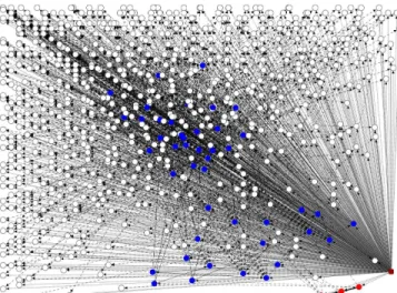
Fig. 12 Smallest experimental graph: A DIET configuration of size 1000 and height 5.
sented in Fig. 11. A configuration may contain several con-nected MAs. As a result, a configuration may exhibit cycles. The manipulated graphs possess the following characteris-tics :
– Each of them has several MAs and at least one cycle. – Trees composed by sub-graphs induced by a MA
along-side the LAs and SeDs it manages do not have the same height. Within such a tree, SeDs do not necessarily have the same depth.
– There exists no n such as any of these trees is n-ary. – Each non-intermediary LA manages at least 100 SeDs.