HAL Id: hal-01662665
https://hal.archives-ouvertes.fr/hal-01662665
Submitted on 13 Dec 2017
HAL is a multi-disciplinary open access
archive for the deposit and dissemination of
sci-entific research documents, whether they are
pub-lished or not. The documents may come from
teaching and research institutions in France or
abroad, or from public or private research centers.
L’archive ouverte pluridisciplinaire HAL, est
destinée au dépôt et à la diffusion de documents
scientifiques de niveau recherche, publiés ou non,
émanant des établissements d’enseignement et de
recherche français ou étrangers, des laboratoires
publics ou privés.
Micromechanical testing of ultrathin layered material
specimens at elevated temperature
Damien Texier, Daniel Monceau, Jean-Claude Salabura, Ronan Mainguy, Eric
Andrieu
To cite this version:
Damien Texier, Daniel Monceau, Jean-Claude Salabura, Ronan Mainguy, Eric Andrieu.
Microme-chanical testing of ultrathin layered material specimens at elevated temperature. Materials at High
Temperatures, Taylor and Francis, 2016, 33 (4-5), pp.325-337. �10.1080/09603409.2016.1182250�.
�hal-01662665�
Micromechanical testing of ultrathin layered
material specimens at elevated temperature
D. Texier
1,2, D. Monceau
1, J. C. Salabura
1, R. Mainguy
1and E. Andrieu
1The mechanical characterisation of ultrathin specimens at very high temperature is challenging in
terms of specimen preparation and mechanical testing under ‘inert’ atmospheres. An experimental
procedure for the local characterisation of mechanical and thermal properties at elevated temperature is
presented. Various common ‘inert’ atmospheres were investigated up to 1373 K in order to identify the
most efficient environmental conditions to prevent surface reactivity and degradation of specimens. A
NiCoCrAlYTa-coated monocrystalline Ni-based superalloy was used to exemplify the capabilities of the
technique because of its high surface reactivity at very high temperature, i.e. oxidation and sublimation.
Purified overpressured argon atmosphere combined with oxygen getters was found to be particularly
suitable for the study of alumina-forming alloys at elevated temperature.
Keywords: Tensile behaviour, Thermal expansion, High temperature, Micromechanics, Controlled atmosphere, Coatings
Introduction
Small-scale mechanical testing is essential for the charac-terisation of miniature devices and graded materials such as (multi-)layered structures. Graded materials are materials having a gradient in properties along one direction. These property gradients may result from layers in coated materials or microstructural evolution of alloys and/or chemical profiles due to interdiffusion or selective high-temperature oxidation, internal oxidation, nitridation, carburation for example. These graded systems are commonly found in industrial applica-tions; they may come from the initial design or be the result of planned lifecycles or inadvertent damages (oxidation, corrosion, irradiation, wear). In this study, investigation will focus on the characterisation of planar graded materials with special emphasis on coated alloys. In multilayer materials, interfaces between layers act as a discontinuity of properties along the gradient direction. Strain incompatibility from one layer to another one may cause stress concentrations, which might be deleterious for the integrity of multilayer materials. Characterisation of the intrinsic mechanical behaviour of the different layers and their in-service evolution is necessary to ensure a reliable design of the entire layered material under thermomechanical loadings.
In the last decade, specimen preparation and experimental set-ups have been developed in parallel to allow room-tem-perature microcharacterisation for microelectromechanical systems (MEMS) applications.1 Different methods to machine
ultrathin specimens are employed in the field of microme-chanics. Ion abrasion (FIB) enables to machine micro- pillar, cantilever or micro-tensile specimens.2–6 This machining
tech-nique enables sampling few micrometres-cube volumes. The broad ion beam technique using the stencil mask methodol-ogy also enables to thin down a higher volume of material
by ion milling, in order to assess the mechanical properties of few-hundred micrometres-long specimens.7 A competitive
solution for producing ultrathin specimens with gauge dimen-sions in a range between one micrometre and few hundreds of micrometres is the lithographic method. This latter method is commonly used in MEMS and was transposed to ultrathin specimen design.8–10 Electrical-discharge machining (EDM)
followed by tripod polishing is also a conventional prepara-tion technique that ensures flatness of few millimetres-long specimens.11–16 In the present study, the preparation of few
centimetres-long specimens was investigated by a mechanical abrasion procedure comparable with the tripod polishing men-tioned above. In parallel, micromechanical test rigs originally designed for MEMS applications have been subsequently adapted for high-temperature applications such as aeronau-tical gas turbines, aerospace components, electrical power plants, waste incineration plants or, solid fuel cells. Several solutions already exist for the assessment of small-scale mechanical properties at high temperature i.e. micro-inden-tation,17, 18 micro-tensile tests,11–16 micro-pillar compression,19
shearing20 or punch tests.21 Each of these solutions is
perti-nent and has several advantages for the investigation of both the elastic behaviour and the first steps of ductility. Even if micro-pillar testing and microindentation are well designed for higher ductility investigation, these techniques do not sample large enough volumes to average the local heteroge-neities present in graded materials, at the mesoscopic scale,
i.e. at the scale of the layers of such materials. Micro-tensile
techniques enabled to sample higher volumes compared to the previous methods and should be relevant tools for assessing the macroscopic behaviour of those layers. However, because of technical choices in the design of the different microten-sile set-ups reported in the literature, the characterisation of the plastic behaviour is controversial.11–16 Due to the very
low section of ultrathin specimens, self-electrical resistance heating is an attractive technique to perform high-tempera-ture experiments with small power consumption. It provides a good accessibility of the specimen, the size reduction of the experimental set-up and no cooling of the tensile line
1CIRIMAT, ENSIACET-INPT, 4, allée Emile Monso – BP 44362, F – 31030
Toulouse, Cedex4, France
2Mechanical Engineering Department, Ecole de Technologie Supérieure,
1100 Rue Notre-Dame Ouest, Montréal H3C 1K3, Québec, Canada *Corresponding author, email [email protected]
is required. However, this technique based on the amount of current going through the specimen section locally over-heats necked sections and regions where damage initiates. In other words, the deformation is progressively limited to hot spots when plasticity occurs on ultrathin specimens. This necking effect is clearly evidenced on tensile curves at high temperatures.22 Further efforts in experimental designs are
required to obtain a better plasticity description of ultrathin tensile specimens. Such considerations are implemented in the present study.
In addition, the high specific surface of ultrathin spec-imens makes them very sensitive to surface conditions. In this study, high temperature is defined as 0.70–0.85 of the liquidus temperature of the material investigated i.e. 1593–1723 K for Ni-based single-crystal superalloys.23
In this range of temperature, surface degradations, such as oxidation, nitridation and/or sublimation, might have a considerable impact on the mechanical characterisation. Although some experiments on ultrathin specimens were conducted under laboratory air conditions,11–15, 21 other
devices integrated surface protection by the use of ‘inert atmosphere’. Atmospheres often considered as ‘inert’ and usually employed for high-temperature experiments are: vacuum,16, 19, 24–29 high-purity argon17 and hydrogenated
argon.30 However, ‘inert atmosphere’ has a different
mean-ing from an oxidation/corrosion and mechanical point of view. A low partial pressure of oxygen is sometimes not enough to protect the specimen from oxidation whatever the total pressure. For instance, none of these atmospheres are totally inert for α-alumina-forming alloys due to the very high stability of this oxide. In fact, α-Al2O3 formation occurs
for partial pressures of oxygen above 10−28 Pa at 1373 K. In
addition, it has been shown that the growth rate of α-Al2O3
on Ni-based single-crystal superalloys is not particularly sensitive to the external partial pressure of oxygen. In other words, α-Al2O3 layer grows almost as fast in high-purity argon (gas flow) as in air.30, 31 The growth of an oxide layer
at the surface of a sample can affect the surface conditions of the specimen but also the volume properties.30 Indeed,
surface modifications might easily appear triggering deg-radation mechanisms such as bearing section due to oxide scale, strengthening due to tough interface in comparison with a free surface, roughness of the specimen. Moreover, oxidation is a selective phenomenon that may induce soften-ing/strengthening of solid solutions, phase transformation, oxygen diffusion and vacancies injection. Hence, oxidation may induce subsurface and bulk degradations. As mentioned previously, oxidation is not the only source of degradation. Sublimation phenomenon might occur under vacuum at ele-vated temperature. This selective phenomenon, evidenced during high-temperature in situ characterisation,32 is not
discussed from a mechanical point of view.
In the present study, the description of elastic as well as plastic behaviour of materials using ultrathin specimens has been attempted. An innovative characterisation technique involving ultrathin but long and large specimens and mechan-ical testing in controlled atmospheres will be detailed. Those dimensions are long enough to statistically sample the het-erogeneities present in coatings or layered microstructures and are hence reliable for further mechanical modelling approaches. In the first part of the paper, the experimental development has been detailed i.e. the extraction of ultrathin ribbon specimens and the mechanical set-ups. Then, the per-formance of both the specimen preparation and the mechan-ical tests are discussed with a strong emphasis on atmosphere conditions.
Experimental development
Material
The layered material used for this study was a first-generation single-crystal Ni-based superalloy MC2 (nominal compo-sition, in at. % Ni–8.9Cr–5.1Co–1.3Mo–2.5 W–10.7A1– 1.8Ti–2.0Ta) coated with a 70 μm-thick NiCoCrAlYTa layer (nominal composition, in at. % Ni–19.8Cr–17.2Co–0.2Mo– 0.5W–17.2A1–0.1Ti–1.3Ta–0.8Y), elaborated by electro-chemical deposition (TRIBOMET Process). Monocrystalline MC2 rods were directionally casted by withdrawal process on <001> seeds and then subjected to the standard solutioning treatment: 3 h at 1573 K. Fifty-millimetre-long, 8-mm-wide and 1-mm-thick plates were electro-discharge machined with the long axis of the specimen along the [001] direction while the flat face was parallel to the (100) plane. Faces were ground then grit-blasted prior to the TRIBOMET process. Coated plates were heat treated for 6 h at 1353 K followed by air-cooling and 20 h at 1143 K in a static overpressured atmosphere of high-purity argon (10 ppm O2 impurities) then final air cooling. The microstructure of the MC2, i.e. the substrate (S.Z. for substrate zone), consists in a regular arrangement of γ′-L12 precipitates, aligned along the <001>
directions of the γ fcc single-crystal solid solution matrix. According to this standard heat treatment, the microstructure of the NiCoCrAlYTa coating (C.Z. for coating zone) con-sists in β-(Ni, Co) Al and γ′-(Ni, Co, Cr)3(Al, Ti, Ta) phases
dispersed into a γ matrix. The complex microstructure of the interdiffusion zone (ID.Z.) results from the cross diffusion of chemical elements between the coating and the substrate, and from parameters of the deposition process.
Extraction of ultrathin ribbon specimens
Fifty-millimetre-long, 2-mm-wide and 1-mm-thick ribbon- shaped specimens were machined out from the coated plates with a Struers Secotom-50 high-precision cutting machine. Edges were then gritted down with a P4000 SiC paper to remove any effect from precision cutting before the extraction of ultrathin ribbon specimens. A Logitech CL50© lapping machine was then used in combination with a PP5GT© preci-sion Jig to extract ultrathin ribbon specimens by an automated mechanical polishing. The commercial PP5GT© precision Jig was re-machined in order to improve the squareness between the vertical shaft and the specimen holder and to enable addi-tional weights. Both modifications aimed to lower vibrations during the specimen’s preparation and thus to allow lower specimen thickness. The thickness of material removal was continuously monitored by a 2-μm accuracy micrometer. During the material removal step, the load applied on the specimens and the plate rotation speed were adjusted to reach an abrasion rate around 100 μm.h−1, down to 100 μm of the
targeted thickness. Accuracy of this measurement enabled a depth location of about 10 μm because of vibrations, abrasive consumption and Jig polishing. When necessary, more accu-rate in-depth specimen extractions were performed during the surface finishing steps by interrupting the thinning down procedure and observing the polished surface and the edge of the specimen with an optical microscope. The observation of the polished surface consisted in following the occurrence and fraction of a microstructural marker in the graded material (grain size, phases occurrence, grit-blasting particles in TBC systems, etc.) while a direct measurement of the specimen thickness was possible on the cross-section observation. This step-by-step method was employed for ID.Z. specimens in
order to position one surface of the specimen at the original interface between the coating and the substrate. During this finishing step, parameters were changed to reach a lower abra-sion rate of 20 μm.h−1. Specimens were finally polished with
diamond pastes down to 1 μm. No curvature of specimen was observed after thinning down homogeneous materials, i.e. S.Z. and C.Z. specimens, even for 20-μm-thick specimens. Curvature could be noticed for graded materials having resid-ual stresses from their fabrication such as ID.Z. specimens. Calibration tests of specimen preparation were previously per-formed on 718 Ni-based polycrystalline superalloy in order to conserve material.33
Mechanical test rig
A mechanical test rig was developed to access tensile, creep and thermal expansion properties at elevated temperature under controlled atmosphere. The general view of this mechan-ical test rig is reported in Fig. 1 and a schematic representation is given in Fig. 2. In the present paper, particular attention was paid to the monotonic tensile testing of ultrathin but long specimens at elevated temperature under controlled atmos-pheres. Due to issues with controlled atmospheres, design of the test rig complies with Ultra-High Vacuum specifica-tions to avoid leakage under vacuum or static overpressured atmosphere.34 The force application is controlled by a
step-by-step external actuator transferring the load to the specimen through a compliant bellows (4 N.mm−1). The step-by-step
actuator used for the displacement-controlled configuration enables testing with a strain rate ranging from 1.0 × 10⁻⁵ s−1
to 0.1 s−1 in continuous mode or a 3.1 × 10⁻⁶ mm incremental
displacement with the step-by-step mode. The load domain ranges from 2.5 N to1 kN. The load is continuously measured by an internal small-dimension load cell (1 or 0.5 kN with a combined error of 0.15% of the nominal load (N.L.)). Load ranging from 0.1 to 25 N has been calibrated with weights measurement in order to improve low load accuracy. Ultrathin
specimens are particularly sensitive to thermal modification and additional loading due to contact with other massive parts. Non-contact measurements were hence employed in this study for both thermal and dimensional measurements (Figs. 1 and 2). S-thermocouple was welded on a platinum plate located near the gauge zone. Two thermal measurements were done along the specimen gauge to control the different zones of the furnace (Fig. 1b). Comparable methods were
already used in previous studies.30, 35
Dimensional variations of the specimen were continuously measured during experiments with a KEYENCE LS7030M optical micrometer using a GaN green LED as light source (Fig. 2: items 5 and 6). The accuracy of the dimensional meas-urements is 0.5 μm at room temperature and 3.0 μm at 1373 K due to natural convection.
A 2-zone halogen lamp furnace (3.2 kW) enabled tempera-ture stability up to 1373 K. Difference in temperatempera-ture between thermocouples was lower than ±0.2 K during dwell and ±2 K during heating at 0.5 K.s−1. Overshoot before dwell did not
exceed 1.5 K. High-performance refractory materials were used in the high-temperature area of the machine.
Key points in the design of the micromechanical set-ups were: (i) Specimen gripping. (ii) Length measurements. (iii) Controlled atmosphere. They are detailed below.
Gripping solution
Low load level (less than 100 N) is enough to cover elastic, plastic and viscoplastic behaviours for a wide range of materi-als when they are a few hundred micrometres thick. Width and length of the specimens are respectively at least one and two orders of magnitude higher than the thickness. Due to these dimensional ratios, handling of the specimen can be possible by friction (Fig. 3). The friction gripping solution corresponds to a homothetic resizing of self-tightening grips (Fig. 3b). The
choice of the grip material was adapted to the specimen tested at high temperature to ensure a good mechanical strength and a compatibility of thermal strains. AM1 Ni-based single- crystal superalloy and alumina were used in the present study for the characterisation of coated Ni-based superalloys. This gripping solution can transmit a load of about 160 N at room temperature and of more than 100 N up to 1373 K with-out slippage of the specimen. Position of the specimen into grips was compared by optical microscopy before and after mechanical tests at elevated temperature to check slippage of the specimen.
Strain calculation
In the present study, ribbon-shaped specimens do not have any feature to screen the laser light sheet for dimensional measurements. Therefore, grips displacement (Items 4 and 7 in Fig. 2a and ΔLgrip(t) label depicted in Fig. 2b) is suitable
for the calculation of the strain due to the absence of slip-page. With this technique, strain calculation is different for mechanical testing at stabilised temperature and for thermal expansion measurement. In the case of mechanical testing at a stabilised temperature, the dimensional variations are attributed only to the gauge length of the specimen (distance between the bases of the square grips). Grips are considered as non-deformable regarding the level of load applied. However, for thermal expansion measurements, blank measurements were performed for a constant heating rate of 0.5 K.s−1 in order
to subtract the thermal dimensional variation of the grips from one of the specimens (Fig. 2: items 4 and 7).
1 (a) General view of the mechanical test rig. (b) Magnification on the specimen, grips and temperature measurement
are known to contain volatile metallic elements and are prone to α-alumina formation. On top of that, α-alumina layer may grow as fast in high-purity argon as in air as mentioned in the introduction.30, 31 In this range of temperature, common ‘inert
atmospheres’ are not efficient to prevent the specimens from oxidation and/or sublimation.30–32
Different atmosphere conditions were investigated in the present study:
• Secondary vacuum: Primary vacuum (Ptot = 5.0.10−3 mbar) followed by a secondary vacuum
at room temperature lead to a partial pressure of oxy-gen about 5.0.10−7 mbar. Once such a vacuum level was
reached, heating procedure was run for high-temperature dwell experiments.
• High-purity argon – static overpressured atmosphere: A first purge of high-purity argon was performed to avoid contamination from the gas injection line. High-purity argon contained about 10 ppm of O2 and H2O impuri-ties. Secondary vacuum up to 2.0.10−6 mbar at room
temperature was carried out. Then, high-purity argon was injected up to 200-mbar overpressure at room tem-perature and the vessel was sealed. Heating procedure was finally run for high-temperature dwell experiments. • High-purity argon – static overpressured atmosphere
with O2 and H2O purification: A special procedure with
changes in atmospheres has been adopted to limit the partial pressure of water and oxygen into the vessel. Zr shavings acting as O2 getters were introduced in the high-temperature area of the vessel close to the Ar injec-tion tube (Fig. 2: item 2 and 3). For the same reasons than for the previous atmosphere condition, a first purge of high-purity argon followed by a secondary vacuum at room temperature was performed. A first dwell under vacuum at intermediate temperature helps for water des-orption. Then high-purity argon was injected at interme-diate temperature. High-purity argon static atmosphere combined with presence of Zr shavings leads to O2 impurities consumption in the atmosphere before car-rying out high-temperature experiment.
Characterisation techniques
Cross-section observations
After thinning down the specimens, some were dedicated for thickness profile measurement. They were prepared for cross-section observations using Cu plating, cold epoxy
Controlled atmosphere
The goal of this study is to identify bulk properties using ultrathin specimens. Special attention was paid to atmosphere conditions at high temperatures. Various gases can be intro-duced inside the vessel with a static or flowing gas configu-ration. Oxygen getters such as zirconium are introduced in the hot zone close to gas inlet in order to lower the partial pressure of O2 (Fig. 2: item 3).
Atmosphere conditions have to be adapted to the material tested. Sublimation can occur at elevated temperature under dynamic vacuum conditions, whereas alloys forming very stable oxides such as Al2O3, SiO2, ZrO2, TiO2 need very low
partial pressure of dioxygen and water vapour to avoid oxi-dation. Such considerations have been taken into account. Materials, temperature range and atmosphere conditions were chosen to test the limit of the test rig in this study. Materials investigated were Ni-based single-crystal superalloys, which 3 (a) Friction solutions for gripping ultrathin specimens
during mechanical tests at elevated temperature. (b) Typical fracture of ultrathin specimens after mechanical test at elevated temperature
qualitative factor for thickness estimation of the oxide layer when this one was lower than the interaction volume activated by the laser.
Experimental results
Extraction of ultrathin ribbon specimens
Thickness variation along the gauge zone
With slight modifications of the commercial lapping devices, it was possible to prepare specimens down to an 18 μm thick-ness. A constant thickness over a long and ultrathin specimen is difficult to obtain. Defects in parallelism and edge effects have to be minimised. Therefore, two different configura-tions of specimen disposition have been investigated (Fig. 4). Thickness profile along the gauge length of the specimen was quantified by image analysis. Results from these analy-ses are reported in Fig. 4. This complementary verification aims to validate the thickness measurement carried out with contact micrometer for further mechanical testing. Thickness variation along the gauge does not exceed ±1 μm regarding the mean value, whatever the configuration. No accidental variation of thickness was noticed.
For ribbon-shaped specimens prepared with the config-uration 1, the extremities of the specimen were blunted on less than 3 mm. Figure 5b also shows that edges of specimens
were blunted on 150 μm with a maximal depth of 4 μm at the extremity. SEM observations of specimen sides evidenced that the maximal depth of smoothed edge was about 3 μm. A shape factor was then taken into account for the calculation of the effective gauge section of the specimens. Such blunted edges are particularly interesting for accurate extraction at a specific location since observation of the blunted edges give a preview of the microstructure located 3 μm beneath the main surface during the finishing step. This configuration is of major interest for the extraction of ID.Z. specimens. For additional materials placed beside each other (configuration 2), gauge zones do not exhibit blunted areas.
Calibration tests of the specimens’ preparation technique were conducted in a previous study.33 Statistics on the
prepa-ration of 100 IN718 specimens evidenced that thickness vari-ation does not generally exceed ±1 μm. Accidental varivari-ations in thickness (±2.5 μm) were noticed only for thick specimens and corresponded to 1% of the mean thickness of the spec-imens prepared. Thickness variation was always less than ±0.5 μm for specimens thinner than 100 μm. The maximum relative error for thickness variation was 2.5% of the speci-men thickness in the case of 20-μm-thick specispeci-mens. mounting and polishing down to 1-μm diamond particles. Optical
microscopy using ×500 magnification allowed a 0.35-μm minimal spatial resolvable distance due to the chosen aper-ture. Thickness profiles were then measured via a specific algorithm developed on ImageJ, an image analysis software. Cross-section observations were also conducted using a LEO435VP scanning electron microscope (SEM) operating at an accelerating tension of 15 kV in a backscattered elec-trons (BSE) mode.
Mass gain/loss evolution
Mass gain evolutions were investigated for vacuum and over-pressured high-purity argon atmospheres. For each atmos-phere condition, four specimens were weighted before and after thermal exposure with an accuracy of 10 μg. In a first approximation, a linear and a parabolic constant were calcu-lated for sublimation and oxidation, respectively.
Chemical analyses of material redeposition
After high-temperature dwells in some atmosphere condi-tions, material deposition was observed on the quartz tube. To analyse the nature of this material deposition, a small silica plate was placed in a cooler region of the vessel and then analysed by X-ray Photoelectron Spectroscopy (XPS). XPS measurements were carried out with a Kα spectrometer from Thermo Scientific, using the monochromatised Al Kα line at 1486.6 eV. Photoelectron spectrums were calibrated in binding energy compared to the energy of the metallic Ni (852.8 ± 0.1 eV).
α-alumina detection
A SEIFERT 3000TT X-ray diffractometer with a copper source was used between 20° and 110° with a 0.02° step in a fixed low-angle configuration (2° and 4°) to amplify response from the surface.
Cr dissolved into α-alumina provides an intense signal of fluorescence, which was measured with a HORIBA YVON JOBIN Raman microscope. This allows the detection of very low content of α-alumina. Photoluminescence spectroscopy analyses were carried out on specimens after high- temperature dwells in different atmosphere conditions (secondary vacuum, high-purity argon with or without baking and presence of O2 getter). Analysis time/signal intensity ratio was used as a
the results. Furthermore, the thermal expansion measurements for the different materials were compared with measurements performed on bulk specimens (dashed curves) with a con-ventional SETARAM dilatometer.35–37 Coefficients of thermal
expansion obtained for the different materials are summarised in Table 1. These values are consistent with the literature data.
Mechanical experiments on ultrathin specimens
To illustrate the performance of the mechanical test rig, tensile experiments were performed also on freestanding specimens extracted at different depths in the gradient of microstruc-ture of a NiCoCrAlYTa-coated monocrystalline superal-loy MC2, i.e. in the coating (C.Z.), the interdiffusion zone (ID.Z.) and the substrate (S.Z.). Tensile tests were conducted under displacement control with a strain rate of 5 × 10⁻⁵ s−1.
Stress–strain curve obtained for C.Z. specimens are pre-sented in Fig. 7 in order to illustrate the significant ductility of NiCoCrAlYTa alloys above the 923 K. The mechanical strength of the coating was shown to decrease with the tem-perature in the range of temtem-peratures investigated. C.Z. failed in a quasi-brittle manner close to 923 K and appreciable duc-tility is noticed for higher temperatures. Those elongations to fracture are compared in Fig. 8 with results obtained on bulk NiCoCrAlYTa specimens.37 C.Z. specimens demonstrate
lower strain-to-failure than bulk NiCoCrAlYTa at low tem-peratures and higher ductility above 1073 K. Interestingly, strain-to-failure are in the same order of magnitude in this range of temperature.
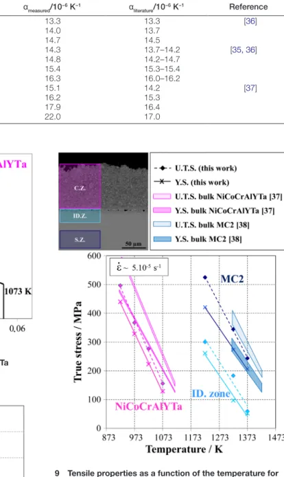
The 0.2 pct. offset yield strength (Y.S.) and the ultimate tensile strength (U.T.S.) of the different layers were reported in Fig. 9. The tensile properties of the coating and the monocrystalline superalloy obtained on ultrathin specimens were compared with the one measured on bulk specimens (see coloured domains in Fig. 9) on conventional test rigs. The dark and light pink-coloured domains depict Y.S. and U.T.S. for bulk NiCoCrAlYTa at various temperatures ranging from 923 to 1123 K with a strain rate of 1.10−4 s−1, respectively.37 For
Accuracy in specimen extraction at specific depth location
Some specimens were extracted from the interdiffusion zone in a NiCoCrAlYTa-coated Ni-base single-crystal superalloy with the configuration 1 specimen preparation. Figure 5a
illus-trates a cross-section of an ID.Z. specimen. This 37-μm-thick specimen was previously thinned down according to the pro-cedure described before. Particular attention was paid to the preparation of interdiffusion zone specimens in order to be located at the original coating/substrate interface. Figure 5
puts in evidence the accuracy of depth location of the extrac-tion procedure. The original interface between the coating and the superalloy was peppered with alumina particles coming from prior grit-blasting of the substrate. Grit-blasting parti-cles (black partiparti-cles in backscattered electron mode) could be observed on both the cross-section (Fig. 5a) and the top
view (Fig. 5b) of the specimen. Top view observation revealed
that most of the surface was located at the interface (region peppered with alumina). It can be seen on the top view that 70–85% of the surface corresponds to the ‘interface region’. The rest corresponds to the ‘cellular recrystallisation’ zone due to slight blunting at specimen edges inherent to the spec-imen preparation.
Mechanical test rig
Thermal and dimensional stability
The precision of thermal expansion measurement was evalu-ated for different materials including Ni-based single-crystal superalloy (MC2 and AM1) and NiCoCrAlYTa coating in different ranges of temperature (Fig. 6). Different thicknesses were tested, depending on the material. NiCoCrAlYTa free-standing coating and AM1 specimen were 57 and 35 μm thick, respectively, whereas MC2 specimen was 130 μm thick. Thermal expansion measurement of MC2 was performed for two different specimens in order to test the reproducibility of 5 Accuracy of specimen extraction: case of specimen
preparation from the interdiffusion (ID.) zone. (a) Cross-section of the ID. zone specimen. (b) Top view observation of the ID. zone specimen. Magnifications of the grit-blasted ‘interface’ (bottom) and of the cellular recrystallisation region (top)
6 Thermal expansion measurements as a function of the temperature for monocrystalline superalloys (MC2 and AM1) and a freestanding NiCoCrAlYTa coating. Comparison between ultrathin (solid line) and bulk (dashed line) specimens measurements (reader may refer to the online version of this article for colour legend)
materials, the yield strength of ultrathin specimens is in closer agreement with the one of bulk specimens than the U.T.S. This observation could be the consequence of microstructural dif-ferences, ‘size effect’ or the results of slight difference in strain rate since both the materials are strain-rate sensitive in this range of temperatures. However, mechanical results obtained on ultrathin specimens are consistent with the literature.
In addition, creep experiments under a small load at 1373 K were already performed in a recent study on MC2 Ni-based single-crystal superalloy specimens with this mechanical test rig.39
Controlled atmosphere
Different atmosphere conditions have been experienced in this study in order to investigate their effect on surface bulk MC2, the dark and light blue-coloured domains depict
Y.S. and U.T.S. at various temperatures ranging from 1323 to 1423 K with strain rates between 1.10−5 and 1.10−4 s−1,
respec-tively.38 The lower and upper limits of the coloured domains
correspond to the lowest and highest strain rates. For both
Table 1 Comparison with the literature of coefficients of thermal expansion measured for different materials
Material Temperature/K αmeasured/10−6 K−1 αliterature/10−6 K−1 Reference
AM1 973 13.3 13.3 [36] 1073 14.0 13.7 1173 14.7 14.5 MC2 973 14.3 13.7–14.2 [35, 36] 1073 14.8 14.2–14.7 1173 15.4 15.3–15.4 1273 16.3 16.0–16.2 NiCoCrAlYTa 873 15.1 14.2 [37] 973 16.2 15.3 1073 17.9 16.4 1173 22.0 17.0
7 Stress–strain curves of freestanding NiCoCrAlYTa specimens at 923, 973, 1023 and 1073 K
8 Comparison of the strain-to-failure between ultrathin and bulk NiCoCrAlYTa specimens37
9 Tensile properties as a function of the temperature for freestanding specimens extracted at different depth of the NiCoCrAlYTa-coated Ni-based superalloy MC2 (Top left incrustation picture). Comparison between ultrathin and bulk (coloured domains) specimen measurements (reader may refer to the online version of this article for colour legend)
thickness of the specimen, similar to what happened with high-temperature oxidation.
High-purity argon – static overpressured atmosphere
High-purity argon – static overpressured atmosphere was used to have a high total pressure but low partial pressure of oxygen in the vessel. No sublimation of materials was noticed even after a 47-h dwell at 1373 K. The same approach used for the sublimation analysis allowed quantifying the oxidation of the specimen. After a 20-h exposition at 1223, 1323, 1373 and 1423 K, the mass gain cumulated on the different specimens were about fifty times higher than the content of oxygen intro-duced by the high-purity argon atmosphere. Assuming there is no leakage of the vessel, water and oxygen desorption from the vessel and the tensile line could explain this difference. XRD analyses enabled to identify both alumina and chromia oxides. These analyses were also confirmed with Raman anal-yses. No change in the silica plate colour and no screening of the quartz tube were noticed. In addition, XPS analyses of the silica plate did not reveal the occurrence of elements constitutive of the superalloy. In other words, it was shown that this procedure prevents the specimen from sublimation but not from oxidation.
High-purity argon – static overpressured atmosphere with O2 and H2O purification
A special baking procedure was conducted prior to a 44-h exposition time at 1373 K under high-purity argon – static overpressured atmosphere combined with Zr shavings used as oxygen getters. The special baking consisted in first desorbing water under a secondary vacuum then progressively injecting high-purity argon at a temperature at which the specimen sur-face reactivity is negligible. No change in silica plate colour and no screening of the quartz tube were noticed after this long dwell at high temperature. XPS analyses of the silica plate did not reveal the presence of element constitutive of the superalloy. No change in colour of the Ni-based superal-loy specimens was noticed. XRD analyses did not reveal the presence of alumina or chromia. This atmosphere and pro-cedure were found to be particularly suitable for preventing specimens from surface degradation at very high temperature.
Effect of atmosphere on the microstructure of the near surface region
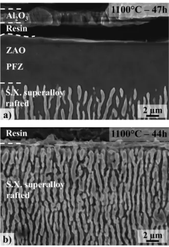
In the Ni-based single-crystal superalloy, γ′ precipitates (light grey phases in Fig. 11) correspond to an Al reservoir. Al con-sumption due to α-alumina formation at high temperature gen-erates a precipitate-free zone underneath the surface. Figure
11 shows how the zone affected by oxidation (ZAO) varies with atmosphere conditions prior to the high-temperature dwell. The precipitate-free zone is about 6 μm after 47 h at 1373 K in static high-purity argon without prior baking (Fig.
11a). Prior baking, which is designed to purify the atmosphere
from residual H2O and O2, induces no γ′ depletion zone for an equivalent temperature/time experiment (Fig. 11b).
Characterisation of surface reactivity in the studied atmospheres
Figure 12 reports photoluminescence spectroscopy (PLS) analyses performed with a Raman spectrometer on specimens having evolved in different atmosphere conditions, i.e. vac-uum, high-purity argon with or without baking and presence of O2 getters. A 1-s acquisition time was enough to detect a
high-intensity peak for a thick alumina layer for the speci-men that was annealed under high-purity argon without prior degradation and therefore their noxiousness on the
mechan-ical testing. The case of an α-alumina-forming superalloy (MC2) was studied in detail at very high temperature.
Vacuum
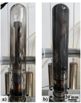
In the present study, sublimation of materials was evidenced for different dwells at high temperature under a secondary vacuum and materials deposition was noticed on the quartz tube, as depicted in Fig. 10. Dedicated tests were performed to quantify the sublimation kinetics under those secondary vacuum conditions (Ptot = 2.0.10−9 bar) at 1223 K. After a 12-h
dwell at 1223 K, material deposition on the quartz tube was sufficient to totally hinder the optical observation of sample through the quartz tube (Fig. 10a). After the experiment, XRD
analyses of the MC2 sample with low incidence angle (2° and 4°) did not show any trace of alumina and chromia oxides. A silica plate was added in the high temperature parts of the vessel to investigate the sublimation phenomenon. The colour of the silica plate changed after the experiment due to material deposition. Mass loss measurements of the samples were done in parallel to calculate the constant rate of sublimation for the MC2 Ni-based single-crystal superalloy. It was found that
ksublim(1223 K) = 6.5.10−10 g.cm−2.s−1. This constant may be
underestimated because of the slight oxidation of the speci-men. Sublimation is a thermo-activated phenomenon, which increases for higher temperatures as shown by the deposition on the tube’s internal surface (Fig. 10b). After the sublimation
test, XPS analyses of the silica plate revealed the presence of Al, Cr, Ni and Co. Quantitative analyses of the chemical composition of the deposition layer (50Al–30Ni–20Cr in at. %) evidenced differences with the nominal composition of the superalloy used. Clearly, Al vaporises faster than the other elements. Sublimation is a selective phenomenon, which might then induce a gradient of chemical composition in the 10 Illustration of sublimation after dwell at elevated
temperature under secondary vacuum. (a) 1223 K – 14 h. (b) 1323 K – 6 h
Discussion
Extraction of ultrathin ribbon specimens
Ultrathin but long specimens can be machined with the method described previously. Tolerance on specimen dimen-sions has to be controlled and compared with current stand-ards. ASTM E8/E8M−13a and ASTM E345–93 for tensile experiments on circular and foil specimens impose a toler-ance of at least ±1.6% of the diameter for circular specimens. Another requirement is the 2-μm accuracy for thickness meas-urement of flat specimens thinner than 0.5 mm. In this study, the variation of thickness along the specimens is repeatable from one preparation to another one. In comparison with the mean thickness, this variation in dimensions does not exceed ±1 μm and even ±0.5 μm for specimens thinner than 100 μm. To be consistent with the tolerance used for tests on bulk materials, e.g. on 12.5-mm-diameter specimens, the minimum thickness of thin specimens used in this study has hence to be higher than 31 μm.
Nevertheless, tolerance of specimen thickness has to be adapted to the accuracy required for the properties in question. Figure 13 reminds the impact of geometry uncertainties in the determination of tensile and creep properties as a function of either the error in thickness measurement or the thick-ness variation. Figure 13a shows the relative scatter in stress
measurement due to thickness variation of the specimen. As a result, Figs. 13b, c and d highlight the multiplication factor
on the error bar for the steady state creep rate according to different Norton-Bailey exponents (eq. 1).
Numerous experimental developments for very high tem-perature concerned the characterisation of coated materials,
e.g. thermal barrier systems. These systems are constituted
of tens of micrometres-thick layers whose intrinsic properties differ by layer. To access a better description of the mechan-ical properties of such systems, depth location of specimen extraction is also crucial. The technique used in this study complies with these specifications.
Mechanical test rig
Mechanical testing
Mechanical testing on microsized specimens for the deter-mination of macroscopic behaviour laws is subject to con-troversy. As mentioned before, this study aimed to expand the local characterisation capabilities of layered materials’ specimens at elevated temperature. This was done with a particular emphasis on the different layers of material found typically in coated superalloys in order to enrich the database feeding mechanical models for layered materials. We checked that measurements of thermal expansion, Young modulus and yield stress of thin specimens were consistent with measure-ments done on massive and conventional specimens. The use of a furnace to heat specimens enables a better characterisa-tion of the ductility than self-electrical resistance heating, which is subject to local overheating at the necking or near defects. A good description of ductility is important for all materials but especially for coating materials which need to follow the strain imposed by the substrate without cracking.
In the light of the consistency of the results obtained in the present study, scientific issues can be raised. We can wonder if the mechanical properties of our ultrathin specimens are representative of volume properties. For these high surface/ volume ratio specimens, the challenge is to avoid surface
(1)
̇ 𝜀 = K.𝜎N
baking. But an analysis of 180 s was necessary for having enough signals for the specimen oxidised under argon atmos-phere with previous baking and O2 getters. The ‘acquisition
time/signal intensity’ ratio was about 104 lower when prior
baking was used. The thickness of the oxide analysed was well below the interaction volume. Atmosphere control was then shown to be successful for Ni-based superalloys. Finally, the solution found consists in forming a very thin oxide (alu-mina) layer, which prevents metal sublimation and does not cause alloying element depletion in the superalloy.
11 Cross-section of two MC2 Ni-based superalloy specimens after ca. 45-h dwell at 1373 K. (a) without prior baking. (b) with prior baking and O2 getters
12 Photoluminescence spectroscopy (PLS) spectra for the characterisation of α-alumina after dwell at elevated
results are consistent with bulk characterisation reported in the literature (Figs. 6–9), we think that the latter properties measured in the present study are representative of volume behaviour and can be used as database for further lifetime and behaviour models.
Controlled atmosphere
In the present study, various atmospheres were investigated in order to prevent very high specific surface area specimens from surface degradation. From a thermodynamic perspec-tive, secondary vacuum does not prevent the specimen to form an α-alumina scale. But with a secondary vacuum, there is a competition between oxide formation and sublimation of metal due to high vapour pressure of some constitutive alloy elements. Both phenomena lead to surface degrada-tion. Al, Cr, Ni, Co present relatively high vapour pressure above 1073 K.40 In a static atmosphere, sublimation may
stop when the vapour pressure of metals are reached in the vessel. Nevertheless, matter flow due to convection and con-densation on cooler surfaces leads to a continuous sublima-tion of the specimen. This phenomenon is enhanced in the case of vacuum tests under continuous pumping. Mendis and Hemker evidenced also this rapid sublimation during TEM observation of a MCrAlY alloy during in situ annealing at 1173 K.32
damages (high-temperature oxidation, sublimation, nitrid-ing, elemental depletion) and to avoid ‘size effects’ from a mechanical point of view. Environmental conditions were controlled to avoid surface degradation at high temperature. As far as the ‘size effects’ are concerned, the volume sam-pled is sufficient to capture most of the material’s heteroge-neities. The fact that we are using much longer and larger specimens in our study implies that the volume tested is about 40 times higher for a similar thickness of dogbone or plate specimen.11–16 Interestingly, the main effect of testing long
specimens was to lower the scatter in experimental results.33
Therefore, a better description of macroscopic behaviours, especially ductility, was possible by combining this specimen geometry and this new mechanical set-up. The ductility of ultrathin freestanding C.Z. specimens was shown to be con-sistent with results obtained on the same bulky material.37 It
is well known that ribbon-shaped specimens are not the best specimen geometry to assess mechanical properties, but it was sufficient to highlight the potential of this mechanical test rig. Further conventional plate specimen geometries with wider gripping heads are prescribed for further studies.
Even if volume considerations were taken into account through the representativeness of the specimens, surface effects such as the softening effect due to the presence of a free surface, cannot be avoided for such high surface/volume ratio geometries. Given that the tensile and thermal expansion
13 Effect of thickness variation on the scatter in mechanical characterisation for different specimen thicknesses. (a) Stress evolution, (b), (c) and (d) Multiplication factor of steady-state creep rate with different Bailey-Norton exponents
much higher oxidation kinetics than Ni-based single-crystal superalloys at intermediate temperature from a kinetic point of view and they can form a more stable oxide than alumina if they are placed at a lower temperature than the specimen. The use of Zr shavings in the furnace tube is intended to purify the static atmosphere from oxygen, before performing the high-temperature tests. Dwell time and temperature of the purification step have to be chosen according to the material being tested and the temperature range of the experiment. Specimens have been successfully protected from sublimation and oxidation degradation up to 1373 K. This was done thanks to the formation of a very thin oxide layer.
Oxidised specimens can be considered as a bimaterial or even a trimaterial when phase transformation occurs in the alloy underneath the oxide scale because of selective oxi-dation. A multilayer approach can be employed for inverse parameters identification of coated materials subjected to ten-sile and creep tests.25, 26, 42 In the particular case of Ni-based
single-crystal superalloys, α-alumina formation led to Al con-sumption and then to depletion of γ′ strengthening phase (Fig.
11). Mechanical strength of this zone depleted in strengthening precipitates is usually neglected and this layer is considered Specimen sublimation is detrimental to both the
sur-face reactivity and the optical dimensional measurement of ultrathin specimens. It was then impossible to perform long-term mechanical characterisation under secondary vac-uum for this range of temperature. Instead, it was chosen to use an atmosphere at high total pressure but with a very low oxygen content in order to obtain a very thin and protective oxide scale and prevent sublimation. High-purity argon (Ar with 10 ppm O2 impurities) was first investigated. This low partial pressure of oxygen is thermodynamically enough to form α-alumina, and the quantity of oxygen brought into the furnace can be noticeable when the experiment is done under a gas flow. Therefore, it was decided to work under static conditions. Working in an isolated atmosphere with a static, slightly overpressured, gas atmosphere led to a decrease in the pO2 due to oxygen consumption during oxidation of the line and/or the specimen. This solution aimed to avoid specimen sublimation but did not prevent the specimen from oxidation at high temperature.
Addition of oxygen getters and a special baking proce-dure were shown to drastically reduce the oxidation of high reactive specimens at elevated temperature. Zr shavings have
14 Effect of atmospheric conditions on the scatter in mechanical characterisation for different specimen thicknesses. Stress evolution (a) for short experiments, (c) for long experiments. Multiplication factor of steady-state creep rate (b) for short experiments, (d) for long experiments
integrate microstructural heterogeneities. The close agree-ment in thermal expansion and tensile (strength and strain-to-failure) measurements between ultrathin and bulk specimens demonstrates improvements in local characterisation capabil-ities at high temperatures. Coated superalloy exhibit a strong gradient of mechanical properties at high temperatures with a particularly poor strength of the NiCoCrAlYTa coating above the brittle-to-ductile transition temperature. A procedure to control the atmosphere was found in order to avoid surface degradation of ultrathin specimens even for alumina-forming alloys at very high temperature. Preventing alumina-forming superalloy from excessive oxidation was particularly difficult because of the very high stability of alumina, but it was also necessary to slightly oxidise the alloy in order to prevent its sublimation. The effect of such atmospheric degradations (oxidation, sublimation) is particularly critical when deal-ing with high surface/volume ratio specimens and materials subjected to phase transformations and has been qualitatively documented in the present paper. This technique can be used for the local mechanical characterisation of graded materials such as coated materials, materials presenting surface degra-dation (oxidegra-dation/corrosion, irradiation, machining, oxygen embrittlement) or surface treatments (grit blasting, carbura-tion, nitridation). This paper shows the level of control of specimen thickness and atmosphere required to investigate the mechanical behaviour of specimens with high surface/ volume ratio at elevated temperatures.
Acknowledgements
The authors are particularly grateful to Turbomeca–SAFRAN group for providing the materials. This work was part of a research programme supported by DGA involving Snecma-SAFRAN group, Turbomeca-Snecma-SAFRAN, ONERA, CEAT and CNRS laboratories (Mines Paris Tech, Institut P’-ENSMA, LMT-Cachan, LMS-X, CIRIMAT-ENSIACET). J. Esvan, C. Charvillat and O. Marsan are hereby thanked for their help in XPS, DRX and Raman analyses. D. Texier is particularly grateful to J. Cormier and J.C. Stinville for their stimulating discussions.
ORCID
D. Texier http://orcid.org/0000-0002-4473-7827
References
1. K. J. Hemker and W. N. Sharpe: ‘Microscale characterization of mechanical properties’, Annu. Rev. Mater. Res., 2007, 37, 93–126.
2. G. P. Zhang, K. Takashima, M. Shimojo and Y. Higo: ‘Fatigue behavior of microsized austenitic stainless steel specimens’, Mater. Lett., 2003,
57, 1555–1560.
3. R. D. Field and P. A. Papin: ‘Location specific in situ TEM straining specimens made using FIB’, Ultramicroscopy, 2004, 102, 23–26. 4. J. R. Greer, W. C. Oliver and W. D. Nix: ‘Size dependence of mechanical
properties of gold at the micron scale in the absence of strain gradients’,
Acta Mater., 2005, 53, 1821–1830.
5. P.A. Shade: ‘Small scale mechanical testing techniques and application to evaluate a single crystal nickel superalloy’, PhD thesis, The Ohio State University, Columbus, 2008, 1–199.
6. D. Kiener, W. Grosinger, G. Dehm and R. Pippan: ‘A further step towards an understanding of size-dependent crystal plasticity: in situ tension experiments of miniaturized single-crystal copper samples’, Acta Mater.,
2008, 56, 580–592.
7. P. A. Shade, S. L. Kim, R. Wheeler and M. D. Uchic: ‘Stencil mask methodology for the parallelized production of microscale mechanical test samples’, Rev. Sci. Instrum., 2012, 83, 053903.
as none-bearing at very high temperatures. A bilayer material model, comparable to the model used by Dryepondt et al. [30], was considered in this study to evaluate the effect of oxidation and sublimation on a Ni-based superalloy at 1223 K (Fig. 14). Figure 14a shows the relative error in stress
meas-urement due to oxidation (grey line) and sublimation (black lines) for 20-, 50- and 200-μm thick specimens. As far as the sublimation effect is concerned, the lower line corresponds to material consumption due to sublimation. The upper line takes into account an estimation of γ′ depleted zone due to the faster consumption of Al. For short-time experiments (Figs. 14a and b), oxidation is more damageable than sublimation but this
trend is reversed for long-time testing. This is due to the par-abolic kinetics of oxidation but linear kinetics of sublimation. The multiplication factor on the steady-state creep rate has been calculated for these same conditions (Figs. 14c and d).
This approach is sufficient for the determination of static mechanical behaviour, such as Young modulus and yield strength. When dealing with viscoplasticity characterisation, the oxidation mechanism and/or the interdiffusion might affect the dynamic behaviour of a material and should be taken into account. Vacancy injection or consumption during oxide growth is respectively associated to cationic or anionic growth mechanisms of oxide scales.30 In the case of cationic
oxidation, the injection of vacancies can be important and may lead to a large oversaturation of defects. A part of these point defects can be diluted in the volume of the materials because of their fast diffusion.43, 44 These vacancies contribute
to the deformation mechanism: they increase the diffusion rate of alloying elements, they increase the rate of dislocations climb, and they can also condensate to form pores. Dryepondt highlighted the dynamic effect of oxidation on millimetre flat specimens of Ni-based single-crystal superalloy by switching atmosphere during creep experiments.30 Because the
coeffi-cients of diffusion of vacancies are orders of magnitude higher than those of alloying elements, oxidation can lead to bulk modification of mechanical behaviour. Vacancies flux might be taken into consideration for dynamic characterisation when selective phenomenon, such as oxidation and sublimation, occur. Environmental problems have to be taken into consid-eration especially for creep experiments. This paper proposes a solution to limit this effect, by forming a very slow- growing oxide scale. Oxide growth is further decreased by the O2
depletion with time in the static atmosphere. Moreover, under such a low oxygen partial pressure, α-alumina is favoured with an expected mainly anionic growth mechanism.31
Conclusions and perspectives
The objective of this work was to characterise the high- temperature mechanical properties at a local scale. The adopted method was to extract ultrathin but long speci-mens in the region to be investigated and to test them with appropriate mechanical set-ups. It was possible to machine specimens with thickness down to 18 μm with a maximum variation of thickness along specimen of ±1 μm and of ±0.5 μm for specimens thinner than 100 μm. Microstructural markers ensured the location of material extraction with a ±3 μm precision in worst case. Mechanical test rigs were developed in order to cover various mechanical tests at high temperature under controlled atmosphere (tensile, creep and thermal expansion). Experimental tests were conducted up to 1373 K. Despite the low thickness of the materials tested, this technique enables to assess the mechanical behaviour of representative specimens because the studied volume can
26. M. Bensch, J. Preußner, R. Hüttner, G. Obigodi, S. Virtanen, J. Gabel, and U. Glatzel: ‘Modelling and analysis of the oxidation influence on creep behaviour of thin-walled structures of the single-crystal nickel-base superalloy René N5 at 980 °C’, Acta Mater., 2010, 58, 1607–1617. 27. M. Brunner, M. Bensch, R. Völkl, E. Affeldt and U. Glatzel: ‘Thickness
influence on creep properties for Ni-based superalloy M247LC SX’,
Mater. Sci. Eng. A., 2012, 550, 254–262.
28. J. H. Cleland, R. R. Hough and R. Rolls: ‘An apparatus for constant stress creep testing in ultrahigh vacuum and in controlled atmosphere conditions’, J. Phys. E., 1976, 628, 8–11.
29. A. C. Lewis, D. Heerden, C. Eberl, K. J. Hemker and T. P. Weihs: ‘Creep deformation mechanisms in fine-grained niobium’, Acta Mater., 2008,
56, 3044–3052.
30. S. Dryepondt, D. Monceau, F. Crabos and E. Andrieu: ‘Static and dynamic aspects of coupling between creep behavior and oxidation on MC2 single crystal superalloy at 1150 °C’, Acta Mater., 2005, 53, 4199–4209. 31. D. Monceau, F. Crabos, A. Malié and B. Pieraggi: ‘Effects of bond-coat
preoxidation and surface finish on isothermal and cyclic oxidation, high temperature corrosion and thermal shock resistance of TBC systems’,
Mater. Sci. Forum., 2001, 369–372, 607–614.
32. B. G. Mendis and K. J. Hemker: ‘Thermal stability of microstructural phases in commercial NiCoCrAlY bond coats’, Scr. Mater., 2008, 58, 255–258.
33. D. Texier: ‘Measurement and evolution of the gradient of mechanical properties in MCrAlY coated MC2 nickel based superalloy system’, PhD thesis, INP Toulouse, Toulouse, 2013, 1–299.
34. B. S. Halliday: ‘An introduction to materials for use in vacuum’, Vacuum,
1987, 37, 583–585.
35. C. Siret: ‘Non-isothermal creep of materials used in helicopter turbine: development and scientific exploitation of a new mechanical test rig’, PhD thesis, INP Toulouse, Toulouse, 2010, 1–236.
36. E. Cavaletti: ‘Investigation and development of diffusion barrier for TBC bond-coatings’, PhD thesis, INP Toulouse, Toulouse, 2009, 1–265. 37. A. Boudot: ‘Properties of high temperature protective coatings for high
pressure turbine blades’, PhD thesis, INP Toulouse, Toulouse, 1999, 1–149.
38. J. Cormier: ‘Non-isothermal creep behaviour at high and very high temperature of the monocrystalline superalloy MC2’, PhD thesis, Université de Poitiers, Chasseneuil-Futuroscope, 2006, 1–219. 39. D. Texier, D. Monceau, R. Mainguy and E. Andrieu: ‘Evidence of
high-temperature strain heterogeneities in a nickel-based single-crystal superalloy’, Adv. Eng. Mater., 2014, 16, 60–64.
40. D. Stull: ‘American institute of physics handbook’, 3rd edn; 1972, New York, NY, McGraw-Hill.
41. M. Taylor, H. Evans, E. Busso and Z. Qian: ‘Creep properties of a Pt– aluminide coating’, Acta Mater., 2006, 54, 3241–3252.
42. B. L. Bates, Y. Zhang, S. Dryepondt and B. A. Pint: ‘Creep behavior of pack cementation aluminide coatings on grade 91 ferritic–martensitic alloy’, Surf. Coatings Technol., 2014, 240, 32–39.
43. R. Peraldi, D. Monceau and B. Pieraggi: ‘Evolution of scale microstructure as a function of scale oxide thickness during oxidation of nickel at 700 °C’,
Mater. Sci. Forum., 2001, 369–372, 189–196.
44. S. Perusin, B. Viguier, D. Monceau, L. Ressier and E. Andrieu: ‘Injection of vacancies at metal grain boundaries during the oxidation of nickel’,
Acta Mater., 2004, 52, 5375–5380. 8. J. N. Florando and W. D. Nix: ‘A microbeam bending method for studying
stress–strain relations for metal thin films on silicon substrates’, J. Mech.
Phys. Solids, 2005, 53, 619–638.
9. S. Gravier, M. Coulombier, A. Safi, N. Andre, A. Boe, J.P. Raskin, and T. Pardoen: ‘New on-chip nanomechanical testing laboratory – applications to aluminum and polysilicon thin films’, J. Microelectromechanical Syst.,
2009, 18, 555–569.
10. W. N. Sharpe, B. Yuan and R. L. Edwards: ‘A new technique for measuring the mechanical properties of thin films’, J. Microelectromechanical Syst.,
1997, 6, 193–199.
11. M. Zupan, M. J. Hayden, C. J. Boehlert and K. J. Hemker: ‘Development of high-temperature microsample testing’, Exp. Mech., 2001, 41, 242–247. 12. Md. Zafir Alam, N. Hazari, V. K. Varma and D. K. Das: ‘Effect of cyclic
oxidation exposure on tensile properties of a Pt-aluminide bond-coated Ni-base superalloy’, Metall. Mater. Trans. A., 2011, 42, 4064–4074. 13. M. Zupan and K. J. Hemker: ‘High temperature microsample tensile
testing of γ-TiAl’, Mater. Sci. Eng. A., 2001, 319–321, 810–814. 14. D. Pan, M. W. Chen, P. K. Wright and K. J. Hemker: ‘Evolution of a
diffusion aluminide bond coat for thermal barrier coatings during thermal cycling’, Acta Mater., 2003, 51, 2205–2217.
15. Md. Z. Alam, D. Chatterjee, S. V. Kamat, V. Jayaram and D. K. Das: ‘Evaluation of ductile–brittle transition temperature (DBTT) of aluminide bond coats by micro-tensile test method’, Mater. Sci. Eng. A., 2010, 527, 7147–7150.
16. A. F. Gourgues-Lorenzon: ‘Effects of oxidation on high-temperature mechanical properties of alloy 600: application to cracking in primary water of nuclear pressurized water reactors’, PhD thesis, Ecole Nationale des Mines de Paris, Evry, 1997, 1–478.
17. B. Passilly, P. Kanoute, F.-H. Leroy and R. Mévrel: ‘High temperature instrumented microindentation: applications to thermal barrier coating constituent materials’, Philos. Mag., 2006, 86, 5739–5752.
18. A. Villemiane: ‘Analysis of the mechanical behaviour of bondcoat alloys for thermal barrier systems from high temperature instrumented microindentation experiments’, PhD thesis, INP Lorraine, Nancy, 2008, 1–314.
19. S. Korte and W. J. Clegg: ‘Micropillar compression of ceramics at elevated temperatures’, Scr. Mater., 2009, 60, 807–810.
20. P. Majerus: ‘New procedures to analyse the deformation behaviour and damage evolution of MCrAlY-coatings in the thermal barrier coating system’, PhD thesis, RWTH Aachen, Jülich, 2003, 1–179.
21. M. Eskner and R. Sandström: ‘Measurement of the ductile-to-brittle transition temperature in a nickel aluminide coating by a miniaturised disc bending test technique’, Surf. Coatings Technol., 2003, 165, 71–80. 22. M. Z. Alam, S. V. Kamat, V. Jayaram and D. K. Das: ‘Tensile behavior
of a free-standing Pt-aluminide (PtAl) bond coat’, Acta Mater., 2013,
61, 1093–1105.
23. T. M. Pollock and S. Tin: ‘Nickel-based superalloys for advanced turbine engines: chemistry, microstructure, and properties’, J. Propuls. Power,
2006, 22, 361–374.
24. M. Benyoucef, A. Coujou, B. Barbker and N. Clément: ‘In situ deformation experiments on a γ/γ′ superalloy strengthening mechanisms’, Mater. Sci.
Eng. A., 1997, 234–236, 692–694.
25. R. Hüttner, J. Gabel, U. Glatzel and R. Völkl: ‘First creep results on thin-walled single-crystal superalloys’, Mater. Sci. Eng. A., 2009, 510–511, 307–311.