HAL Id: hal-01104519
https://hal.inria.fr/hal-01104519v2
Submitted on 29 Jan 2015
HAL is a multi-disciplinary open access
archive for the deposit and dissemination of
sci-entific research documents, whether they are
pub-lished or not. The documents may come from
teaching and research institutions in France or
abroad, or from public or private research centers.
L’archive ouverte pluridisciplinaire HAL, est
destinée au dépôt et à la diffusion de documents
scientifiques de niveau recherche, publiés ou non,
émanant des établissements d’enseignement et de
recherche français ou étrangers, des laboratoires
publics ou privés.
Copyright
OFFICER: A general Optimization Framework for
OpenFlow Rule Allocation and Endpoint Policy
Enforcement
Xuan-Nam Nguyen, Damien Saucez, Chadi Barakat, Thierry Turletti
To cite this version:
Xuan-Nam Nguyen, Damien Saucez, Chadi Barakat, Thierry Turletti. OFFICER: A general
Op-timization Framework for OpenFlow Rule Allocation and Endpoint Policy Enforcement. The 34th
Annual IEEE International Conference on Computer Communications (INFOCOM 2015), IEEE, Apr
2015, Hongkong, China. �hal-01104519v2�
OFFICER: A general Optimization Framework for OpenFlow
Rule Allocation and Endpoint Policy Enforcement
Xuan-Nam Nguyen, Damien Saucez, Chadi Barakat, Thierry Turletti
INRIA Sophia Antipolis M´editerran´ee, France [email protected]
Abstract—The Software-Defined Networking approach permits to realize new policies. In OpenFlow in particular, a controller decides on behalf of the switches which forwarding rules must be installed and where. However with this flexibility comes the challenge of the computation of a rule allocation matrix meeting both high-level policies and the network constraints such as memory or link capacity limitations. Nevertheless, in many situations (e.g., data-center networks), the exact path followed by packets does not severely impact performances as long as packets are delivered according to the endpoint policy. It is thus possible to deviate part of the traffic to alternative paths so to better use network resources without violating the endpoint policy. In this paper, we propose a linear optimization model of the rule allocation problem in resource constrained OpenFlow networks with relaxing routing policy. We show that the general problem is NP-hard and propose a polynomial time heuristic, called OFFICER, which aims to maximize the amount of carried traffic in under-provisioned networks. Our numerical evaluation on four different topologies shows that exploiting various paths allows to increase the amount of traffic supported by the network without significantly increasing the path length.
I. INTRODUCTION
The role of a network is to route each packet from an ingress link (i.e., the link from which the packet entered the network) to an egress link (i.e., the link at which the packet
leaves the network).1 According to operational and economical
requirements, the choice of the egress link to which a packet must be forwarded is dictated by the Endpoint Policy and the actual path followed by a packet in the network is decided by the Routing Policy [1].
Endpoint policies are driven by high-level economical and technical considerations. For example, shared-cost links are often privileged by ISPs and data-centers make sure that packets are delivered to servers able to handle them. On the other hand, routing policies are related to the good use of resources in the network. Shortest-path routing is the most common routing policy. Its advantages stem from the fact that it minimizes the amount of links and nodes traversed by a packet across the network and that routing tables are computed in polynomial time [2] but other routing policies are also possible, for instance, compact routing [3].
From that point of view, respecting the endpoint policy is essential while the routing policy is just a tool to achieve this goal [4]. Unfortunately, relaxing routing policies and
1In this paper we use the terms packet, router and routing table in their
general sense, making no fundamental distinction between packets and frames, routers and switches, or between routing tables and forwarding tables.
removing strong path requirements is not practically doable when the network relies on distributed routing algorithms as it would imply a high signaling overhead to ensure consistency of decisions [5]. But with the advent of Software-Defined Networking (SDN) and OpenFlow in particular, it is now possible to manage routing using a centralized approach without losing in terms of scalability or robustness [6]. OpenFlow allows operators to conceive their network as a black box aiming at carrying packets from sources to destinations [6], [4], [7]. The network thus becomes a single entity that the operator can program instead of a bunch of devices to configure. This is achieved in OpenFlow thanks to a logically centralized controller that fetches information from the network, computes appropriate routes according to the operator wills and network conditions, and then transparently pushes the corresponding forwarding rules into the switches.
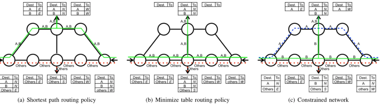
We illustrate the gain from relaxing routing policy in Fig. 1 that shows a symmetric network of 8 switches with two ingress links (East and West) and two egress links (North and South). In this example, the endpoint policy stipulates that destinations
A and B must be reached by the North egress link while
any other destination must be reached by the South egress link. With the shortest path routing policy (Fig. 1(a)), every destination is reached in 3 hops and for a total of 15 routing entries. With a policy minimizing the number of routing entries (Fig. 1(b)), the routing table is reduced to 9 entries but the memory reduction comes at the cost of longer paths for A and
B (i.e., 4 hops). However, in practice networks might have
bandwidth or memory constraints to be respected. For instance, suppose in our network example that each switch can store 2 routing entries. In this case, the two previous routing policies cannot be applied as they would violate the constraints whereas Fig. 1(c) shows an allocation that respects both the endpoint policy and the switches’ constraints.
Departing from the flexibility offered by OpenFlow, we present OFFICER, a general algorithm to calculate and imple-ment efficient forwarding rules in switches. OFFICER treats the network as a black box that must satisfy the endpoint policy imposed by the operator and tries to get the maximum from the available resources by adapting the routes followed by the different packets towards their desired egress links. When the network is under-provisioned, least valuable packets are routed through a default slow path designed to minimize resource usages. As suggested in [4] and [7], we believe that in most networks, enforcing a particular path is not necessary as long as
Dest To A E B E Dest. To A N B N Others E Dest. To Others E Dest. To Others S Dest. To Others W Dest. To A N B N others W Dest. To A N B N Dest. To A W B W A,B A,B A,B A,B
Others Others Others Others A,B
Others
(a) Shortest path routing policy
Dest. To Dest. To Others E Dest. To Others E Dest. To A N B N Others S Dest. To Others W Dest. To others W Dest. To A N B N Dest. To A,B
A,B A,B A,B
A,B
Others Others Others Others A,B
Others
(b) Minimize table routing policy
Dest. To A E Dest. To A N Others E Dest. To Others E Dest. ToB N Others S Dest. To Others W Dest. ToA N others W Dest. To A N B N Dest. To A W B B B B B A A A A
Others Others Others Others A,B
Others
(c) Constrained network
Fig. 1: Example of the routing policy on the path followed by packets
the endpoint policy is respected. Actually, not relying on strict routing policies allows better utilization of the network capacity, reducing so bandwidth wastage and congestion events [4]. Relaxing routing policy is particularly useful in case of scarce network resources as shown in Fig. 1 and in [7].
The remaining of this paper presents our algorithm OFFICER to allocate forwarding rules in OpenFlow networks. This algorithm is the result of a general ILP optimization model formulated in Sec. II, where the OpenFlow network is modeled as a directed graph interconnecting switches and the rules to install on switches are to be found. Our model is general in the sense it can accept any endpoint policies and can accommodate any reward functions (i.e., high-level objective) that the operator aims to maximize. Its novelty can be summarized in two main points: (i) modeling the network as a black box respecting the endpoint policy, and (ii) getting the maximum from the available resources by relaxing routing policy, the rest of the traffic that cannot be installed is routed on a default path. As to be discussed in the related work section (Sec. VI), we are the first to propose a solution making such abstraction of an OpenFlow network, with a clear gain in terms of the volume of traffic that can be correctly assigned to its desired egress point. To illustrate the flexibility of our proposition, we study the particular case of network that is missing memory to account for all forwarding rules in Sec. III. This is a growing problem in networks because of the increase in size of routing tables but also due to the trend to keep outdated routers in operation [8]. This problem can even be exacerbated with OpenFlow as it enables very fine granularity on forwarding decisions. In Sec. IV we numerically evaluate the costs and benefits of relaxing routing policy on ISP and data-center topologies and present different heuristics that approximate the optimal algorithm in polynomial time. We open some discussion in Sec. V and consider the related work in Sec. VI to finally conclude in Sec. VII.
II. GENERAL MODEL TO ALLOCATE RULES INOPENFLOW
In this section, we formalize a general optimization model for OpenFlow rule allocation and endpoint policy enforcement. The goal of the optimization is to find an allocation of forwarding rules in an OpenFlow network such that the
high-level objectives of the operator are respected and network constraints are satisfied. However, depending on the high-level objectives and the network constraints, it may not be possible to satisfy the endpoint policy for every flow and packets of flows that cannot respect the endpoint policy are then forwarded on an arbitrary default path. In the context of OpenFlow, we assume the existence of: (1) a centralized controller that can be reached from every switch in the network and (2) a default path used in every switch to forward packets that do not match
any forwarding rule to the controller.2
Based on these assumptions, our optimization model is expressed as an Integer Linear Program (ILP) with constraints and the goal is to maximize an objective function that abstracts the high-level objectives of the operator. Without loss of generality, we assume that one forwarding rule is used for at most one flow. This assumption is also used in [9] to keep the core simple with exact matching rules and easy to manage flows (e.g., rate limitation, accounting). Moreover this has the advantage of keeping our model linear (see V-B).
In the following, we define a flow f ∈ F as a set of packets
matching a pattern, starting from one ingress link lf ∈ I and
targeting one of the egress links el∈ E(f ). We mean by F the
network workload, I the set of ingress links of the network,
E(f ) ⊆ E is the set of all possible egress links and pf is the
packet rate of flow f .
The optimization builds an |F |-by-|L| Boolean allocation
matrix denoted by A = (af,l), where af,l indicates whether
flow f passes through the directional link l = (u, v); u, v ∈ S+
from node u to node v or not. We refer to Table I for the definition of the different notations used along this paper.
Our optimization model is twofold. One part implements the high-level objectives and the other defines the constraints imposed by the network. For the first part, and without loss of generality, the optimization of the high-level objectives can be written as the maximization of an objective function F(A, . . . ). Additional constraints can be added to account for the real network conditions and to limit the space of possible solutions.
The second part of the model consists of a set of constraints on the allocation matrix A to ensure that network limitations
TABLE I: Notations used for the Optimization model.
Notation Description F Set of flows.
S Set of OpenFlow switches composing the network. Se Set of external nodes directly connected to the network
but not part of the network to be optimized (e.g., hosts, provider or customer switches, controllers, blackholes). S+ Set of all nodes (S+= S ∪ S
e).
L Set of directed links, defined by (s, d) ∈ S × S, where s is the origin of the link and d is its termination. I Set of directed ingress links that connect external nodes
to OpenFlow switches, defined by (s, d) ∈ Se× S.
The particular ingress link of a flow f ∈ F is written lf by abuse of notation.
E Set of directed egress links that connect the OpenFlow switches to external nodes, defined by (s, d) ∈ S ×Se.
L+ Set of all directed links (i.e., L+= L ∪ I ∪ E).
N→(s) ⊆ S+ set of incoming neighboring nodes of switch s ∈ S
(i.e., neighbors from which s can receive packets). N←(s) ⊆ S+ Set of outgoing neighboring nodes of switch s ∈ S
(i.e., neighbors towards which s can send packets). E(f ) ⊆ E Set of valid egress links for flow f ∈ F according to
the endpoint policy.
E∗(f ) ⊆ E E∗(f ) = E(f ) ∪ ∗, where ∗ denotes the set of links attached to the controller.
def (s) ∈ S+ Next hop toward the controller from switch s ∈ S.
M Total switch memory limitation. Cs Memory limitation of switch s ∈ S.
Bl Capacity of link l ∈ L+.
pf Packet rate of flow f ∈ F .
and the endpoint policy are respected. Constraints related to the network are defined so to avoid forwarding loops, bandwidth overload, or memory overflow while endpoint policy constraints ensure that packets can only be delivered to valid egress links. Network constraints: ∀f ∈ F, ∀l ∈ L+: a f,l∈ {0, 1} (1) ∀f ∈ F, ∀s ∈ S : X v∈N→(s) af,(v,s)= X v∈N←(s) af,(s,v) (2) ∀f ∈ F : af,l= ( 0 if l ∈ I \ {lf} 1 if l = lf (3)
Constraint (1) verifies that af,l is a binary variable. To
avoid forwarding loops, acceptable solutions must satisfy flow conservation constraints (2) that ensure that the traffic entering a switch always leaves the switch. Constraint (3) is a sanity constraint. It indicates that among all ingress links, packets of the flow can only traverse the ingress link of f .
Bandwidth Constraints:
∀l ∈ L+ :X
f ∈F
pfaf,l≤ Bl (4)
Constraint (4) accounts for bandwidth limitation and ensures that the sum of the rates of the flows crossing a link l does
not exceed its capacity.3
3The capacity of a link corresponds to the minimum capacity reserved for
delivering packets of flows satisfying the endpoint policy. If the link may be used to forward packets of flows not satisfying the endpoint policy, capabilities must be set up to reserve a capacity of at least Bl on the link for flows
satisfying the endpoint policy, independently of the total traffic carried by the link. Memory Constraints: ∀s ∈ S : X v∈N←(s)\{def (s)} X f ∈F af,(s,v)≤ Cs (5) X s∈S X v∈N←(s)\{def (s)} X f ∈F af,(s,v)≤ M (6)
Constraint (5) accounts for when the memory of each switch is known in advance. On the contrary, when the memory to be allocated on a switch is flexible (e.g., in a Network-as-a-Service context or in virtual private networks where the memory is divided between multiple tenants), the operator may see the memory as a total budget that can be freely divided between switches which is accounted by constraint (6).
To route a flow f via a directed link l = (s, d), a rule must be installed on switch s. However, if the next hop dictated by the forwarding rule is the same as the one of the default action of the switch, it is unnecessary to install the rule. This simple aggregation of forwarding rules is taken into account in constraints (5) and (6). We refer to Sec. V-B for a discussion about rule aggregation.
Endpoint policy constraints:
∀f ∈ F, ∀l ∈ E \ E∗(f ) : af,l= 0 (7)
∀f ∈ F : X
l∈E∗(f )
af,l= 1 (8)
Flows need to satisfy the endpoint policy, i.e., packets of flow f should exit the network at one of the egress points predefined in E(f ). However, it may not be possible to allocate each single flow and thus, some will be diverted to the controller instead of their preferred egress point. Constraint (7) and (8) ensure that the endpoint policy is respected by imposing that packets of a flow either exit at one valid egress link or at the controller. The allocation matrix is a source of information for an operator as it provides at the same time the forwarding table, switch memory occupation, and link usage for a given high-level objective and endpoint policy. It is also important to notice that while a problem may have several equivalent solutions, it may also be unsolvable, depending on the objective function and the constraints. In addition, the general problem is NP-hard as Sec. III-B demonstrates.
III. RULE ALLOCATION UNDER MEMORY CONSTRAINTS
Considering the network as a black box offers flexibility but may lead to the creation of a potentially very large set of forwarding rules to be installed in the network [1], [7], [10]. With current switch technologies, this large volume of rules poses a memory scaling problem. Such problem can be approached in two different ways: either the memory capacity of switches is not known and the problem is then to minimize the overall memory usage to reduce the cost, or the memory capacity is known and the problem becomes the one of finding an allocation matrix that satisfies as much as possible high-level objectives of the operator and the endpoint policy.
In Sec. III-A, we show how to use our model to address the memory minimization problem while in Sec. III-B we use our
model to maximize the traffic satisfaction in case of constrained switch memory. Unfortunately, finding the optimal solution in all circumstances is NP-hard, so we propose a computationally tractable heuristic in Sec. III-C and evaluate different allocation schemes over representative topologies in Sec. IV.
A. Minimizing memory usage
A first application of our model is to minimize the overall amount of memory used in the network to store forwarding rules. This objective is shared by Palette [10] and OneBigSwitch [1], with always the possibility in our case to relax the routing policy and view the network as a black box. To do so, one has to define the objective function so as to count the number of assigned entries in the allocation matrix as detailed in Eq. (9). F(A, S, N←, F ) = − X s∈S X v∈N←(s)\{def (s)} X f ∈F af,(s,v) (9)
Constraint (10), derived from constraint (8), is added to prevent packets to always be diverted to the controller (which would effectively minimize memory usage).
∀f ∈ F :X
l∈∗
af,l= 0 (10)
Parameters Cs, ∀s ∈ S and M used by constraints (5) and (6)
should be set to ∞. However, if for technical or economical reasons the individual memory of switches cannot exceed a
given value, then Cs must be set accordingly.
B. Maximizing traffic satisfaction
When the topology and switch memory are fixed in advance, the problem transforms into finding a rule allocation that satisfies the endpoint policy for the maximum percentage of traffic. The definition given in Sec. III-A is sufficient to this end. It must however be complemented with a new objective function, that models the reward from respecting the endpoint policy where a flow that does not see its endpoint policy satisfied is supposed not to bring any reward. A possible objective function for this problem is:
F(A, F, E) = X f ∈F X l∈E(f ) wf,laf,l (11)
where wf,l∈ R+ is the normalized gain from flow f ∈ F if
forwarded on link l ∈ E(f ). In other words, wf,lrewards the
choice of a particular egress link. In the typical case where the goal is to maximize the volume of traffic leaving the network via an egress point satisfying the endpoint policy, we have
∀f ∈ F, ∀l ∈ E(f ) : wf,l= pf.
Theorem 1. The rule allocation problem defined to maximize traffic satisfaction is NP-hard.
Proof. Let us consider an instance of the problem defined with
the objective function (11), with the topology consisting of one OpenFlow switch, one ingress link, and one egress link e for all flows. Then, let us assume that the switch memory is larger than the number of flows and thus the limitation only
comes from the available bandwidth at the egress link e. The problem then becomes how to allocate rules so as to maximize the gain from the traffic exiting the network at egress link e (the rest of the traffic is forwarded to the controller over the default path). For this instance, we can simplify the problem as follows: maximize X f ∈F wf,eaf,e (12) ∀f ∈ F : af,e∈ {0, 1} (13) X f ∈F pfaf,e≤ Be (14)
This is exactly the 0-1 Knapsack problem, which is known as NP-hard. In consequence, the rule allocation problem defined with the objective function (11) and from which this instance derives is NP-hard.
C. Heuristic
Finding a rule allocation that maximizes the value of the traffic correctly forwarded in the network when switch memory is predefined is not tractable (see Theorem 1). Therefore, an optimal solution can only be computed for small networks with a few number of flows. Consequently, we propose in this section a heuristic to find nearly optimal rule allocations in tractable time. The general idea of the heuristic is described in Sec. III-C1 and the exact algorithm and the study of its complexity is given in Sec. III-C2.
1) Deflection technique: The number of paths between any
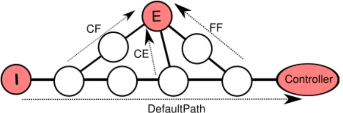
pair of nodes exponentially increases with the size of the network. It is therefore impractical to try them all. To reduce the space to explore, we leverage the existence of the default path. Our idea is to forward packets of a flow on the shortest path between the egress point of the flow and one of the nodes on the default path. Consequently, packets of a flow are first forwarded according to the default action and follow the default path without consuming any specific memory entry, then are deflected from the default path (consuming so memory entries) to eventually reach an egress point. That way, we keep tractable the number of paths to try while keeping enough choices to benefit of path diversity in the network. The decision of using the shortest path between default paths and egress points is motivated by the fact that the shorter a path is, the least the number of memory entries to be installed is, letting room for other flows to be installed as well.
To implement this concept, for every flow, switches on the default path are ranked and the algorithm tries each of the switches (starting from the best ranked ones) until an allocation respecting all the constraints is found. If such an allocation exists, a forwarding rule for the flow is installed on each switch of the shortest path from the selected switch on the default path to the egress point. The rank associated to each switch on a default path is computed according to a user-defined strategy. Three possible strategies are:
• Closest first (CF): as close as possible of the ingress link
E CE CF FF DefaultPath Controller I
Fig. 2: Deflection techniques illustrated with 3 deflection strategies.
Algorithm 1 OFFICER
INPUT: flow weights collection W : F × E → R+, set
of network switches S, set of links L+, set of default path
for flows Def aultP ath, a default path is a set of switches, annotated with a rank, on the path towards the controller.
OUTPUT: A, a |F |-by-|L+| binary matrix
1: A ← [0]F.L+
2: M ← sort(W, descending)
3: for all (f, e) ∈ M do
4: sequence ← sort(Def aultP ath(f ), ascending)
5: for all s ∈ sequence do
6: if canAllocate(A, f, e, s) then
7: allocate(A, f, e, s)
8: break
• Farthest first (FF): as close as possible of the controller.
• Closest to edge first (CE): as close as possible of the
egress link.
In CF (resp. FF) the weight of a switch on the path is then the number of hops between the ingress link (resp. controller) and the switch. On the contrary, the weight of a switch with CE is the number of hops separating it from the egress point. The deflection techniques and the three strategies are summarized in Fig. 2.
2) Greedy algorithm: Algorithm 1 gives the pseudo-code
of our heuristic, called OFFICER, constructed around the deflection technique described in Sec. III-C1. The algorithm is built upon the objective function in (11) that aims at maximizing the overall weight of flows eventually leaving the network at their preferred egress point. The algorithm is greedy in the sense that it tries to install flows with the highest weight first and fill the remaining resources with less valuable flows. The rationale being that the flows with the highest weight account the most for the total reward of the network according to Eq. (11).
Line 2 constructs an order between the flows and their associated egress points according to their weights such that the greedy placement starts with the most valuable flow-egress option. Line 4 determines the sequence of switches along the default path that the algorithm will follow to greedily determine from which switch the flow is diverted from the default path to eventually reach the selected egress point.
The canAllocate(A, f, e, s) function determines whether or not flow f can be deflected to egress point e at switch s
according to memory, links, and routing constraints. Thanks to constraint (8), the canAllocate function ensures that a flow is not delivered to several egress points. Finally, the allocate(A, f, e, s) function installs rules on the switches
towards the egress point by setting af,l = 1 for all l on the
shortest path from the deflection point to the egress point. If there are many possible shortest paths, the allocate function selects the path with minimum average load over all links on that path.
When the number of flows is very large w.r.t. the number of switches and the number of links, which is the common
case, the asymptotic time complexity4 of the greedy algorithm
is driven by Line 2 and is hence O(|F | · log(|F |)). Unfortu-nately, even with the polynomial time heuristic, computing an allocation matrix may be challenging, since this matrix is the direct product of the number of flows and links. For example, in data-center networks both the number of links and flows can be very large ([11]). With thousands of servers, if flows are defined by their TCP/IP 4-tuple, the matrix can be composed of tens of millions of entries. A way to reduce the size of the allocation matrix is to ignore the small flows that, even if they are numerous, do not account for a large amount of traffic and can hence be treated by the controller.
IV. EVALUATION
In this section, we evaluate our model and heuristic for the particular case of memory constrained networks as defined in Sec. III, for Internet Service Provider (ISP) and Data Center (DC) networks. We selected these two particular deployment scenarios of OpenFlow for their antagonism. On the one hand, ISP networks tend to be built organically and follow the evolution of their customers [12]. On the other hand, DC networks are methodically structured and often present a high degree of symmetry [13]. Moreover, while workload in both cases is heavy-tailed with a few flows accounting for most of the traffic, DCs exhibit more locality dependency in their traffic with most of communications remaining confined between servers of the same rack [11].
A. Methodology
We use numerical simulations to evaluate the costs and benefits of relaxing routing policy in a memory constrained OpenFlow network. There are four main factors that can influ-ence the allocation matrix: the topology, the traffic workload, the controller placement, and the allocation algorithm.
1) Topologies: For both ISP and DC cases we consider two
topologies, a small one and a large one. As an example of small topology for ISP we use the Abilene [14] network with 100 servers attached randomly (labeled Abilene in the remaining of the paper). For the large one we use a synthetic scale-free topology composed of 100 switches with 1000 servers attached randomly (labeled ScaleFree).
The topologies for DC consist of a synthetic fat tree with 8 pods and 128 servers (labeled FatTree8) for the small one,
4It is worth to notice that we assume that the algorithm to construct the
0.5 1.0 1.5 2.0 2.5 3.0 3.5 4.0 Capacity 0.0 0.2 0.4 0.6 0.8 1.0
Proportion of traffic covered
CE_MIN RP_MIN OP_MIN CE_MAX RP_MAX OP_MAX (a) Abilene 0.5 1.0 1.5 2.0 2.5 3.0 3.5 4.0 Capacity 0.0 0.2 0.4 0.6 0.8 1.0
Proportion of traffic covered
CE_MIN RP_MIN CE_MAX RP_MAX (b) ScaleFree 0.5 1.0 1.5 2.0 2.5 3.0 3.5 4.0 Capacity 0.0 0.2 0.4 0.6 0.8 1.0
Proportion of traffic covered
CE_MIN RP_MIN OP_MIN CE_MAX RP_MAX OP_MAX (c) FatTree8 0.5 1.0 1.5 2.0 2.5 3.0 3.5 4.0 Capacity 0.0 0.2 0.4 0.6 0.8 1.0
Proportion of traffic covered
CE_MIN RP_MIN CE_MAX RP_MAX
(d) FatTree16
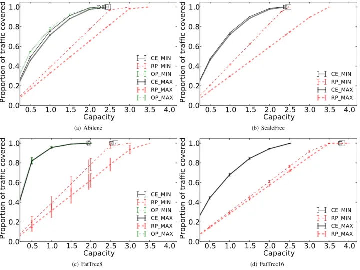
Fig. 3: Proportion of traffic covered and a synthetic fat tree with 16 pods and 1024 servers (labeled
FatTree16) for the large one. Both synthetic topologies are randomly produced by the generator proposed by Saino et al. in [15]. Details of the topologies are summarized in Table II. To concentrate on the effect of memory on the allocation matrix, we consider infinite bandwidth links in all four topologies.
TABLE II: Topology description
Topology Name Type |S| |L| |H| |F | Abilene Small ISP 12 30 100 O(104)
ScaleFree Large ISP 100 292 1000 O(106)
FatTree8 Small DC 80 512 128 O(104)
FatTree16 Large DC 320 4096 1024 O(106)
2) Workloads: For each topology, we randomly produce 24
workloads using publicly available workload generators [15], [16], each represents the traffic in one hour. For each workload, we extract the set F of origin-destination flows together with their assigned source and destination servers. We then use the volume of a flow as its normalized value for the objective
function (11) (i.e., ∀f ∈ F, ∀l ∈ E(f ) : wf,l = pf). A flow
f ∈ F starts from the ingress link of the source server and asks to exit at the egress link of the destination server.
3) Controller placement: The controller placement and the
default path towards it are two major factors influencing the allocation matrix. In the evaluation, we consider two extreme controller positions in the topology: the most centralized position (i.e., the node that has minimum total distance to other nodes, denoted by MIN), and least centralized position (i.e., the node that has maximum total distance to other nodes, denoted by MAX). In all cases, the default path is constituted by the minimum shortest path tree from all ingress links to the controller. The most centralized position limits the default path’s length and hence the number of possible deflection points. On the contrary, the least centralized position allows a longer default path and more choices for the deflection point.
4) Allocation algorithms: To evaluate the quality of the
heuristic defined in Sec. III-C, we compare it with the following two allocation algorithms:
• Random Placement (RP): It is a variant of OFFICER
where flow sets are randomly ranked and deflection points are randomly selected.
• Optimum (OP): The allocation matrix corresponds to
0.5 1.0 1.5 2.0 2.5 3.0 3.5 4.0 Capacity 1.0 1.2 1.4 1.6 1.8 2.0
Average Path Stretch
CE_MIN RP_MIN OP_MIN CE_MAX RP_MAX OP_MAX (a) Abilene 0.5 1.0 1.5 2.0 2.5 3.0 3.5 4.0 Capacity 1.0 1.2 1.4 1.6 1.8 2.0
Average Path Stretch
CE_MIN RP_MIN CE_MAX RP_MAX (b) ScaleFree 0.5 1.0 1.5 2.0 2.5 3.0 3.5 4.0 Capacity 1.0 1.2 1.4 1.6 1.8 2.0
Average Path Stretch
CE_MIN RP_MIN OP_MIN CE_MAX RP_MAX OP_MAX (c) FatTree8 0.5 1.0 1.5 2.0 2.5 3.0 3.5 4.0 Capacity 1.0 1.2 1.4 1.6 1.8 2.0
Average Path Stretch
CE_MIN RP_MIN CE_MAX RP_MAX
(d) FatTree16
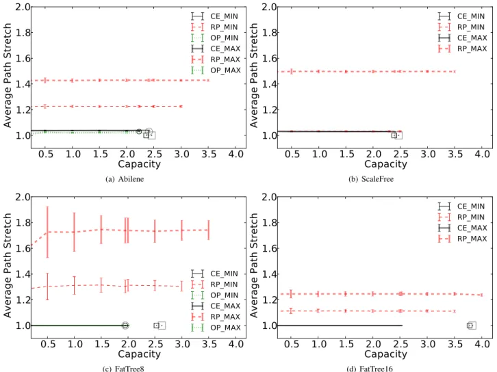
Fig. 4: Average path stretch of deflected flows
using CPLEX.5Unfortunately, as computing the optimum
is NP-hard, it is impossible to apply it to the large ISP and large DC topologies.
Because of room constraints, we only present results for the CE strategy to choose the deflection point. Nevertheless, with extensive evaluations, we observed that this strategy outper-forms the two others by consuming less memory resources. B. Results
In this section, we compare rule allocation obtained with OFFICER with the optimal allocation and random allocation. We also study the impact of the controller placement on the allocation. The benefit of OFFICER is identified as the amount of traffic able to strictly respect the endpoint policy while the drawback is expressed with the path stretch. We also link the number of flows passing through nodes with their topological location.
In Fig. 3 and Fig. 4, the x-axis gives the normalized total memory capacity computed as the ratio of the total number of forwarding entries to install in the network divided by the number of flows (e.g., a capacity of 2 means that on
5http://www-01.ibm.com/software/commerce/optimization/cplex-optimizer/
average flows consume two forwarding entries). Thin curves refer to results obtained with the controller placed at the most centralized location (i.e., MIN) while the thick curves refer to results for the least centralized location (i.e., MAX). The y-axis indicates the average value and standard deviation over the 24 workloads for the metric of interest. Curves are labeled by the concatenation of their allocation algorithm acronym (i.e., CE, RP, and OP) and their controller location (i.e., MIN and MAX).
Reference points indicate the value of the metric of interest if all flows are delivered to their egress link when (i) strictly following the shortest path and denoted with a square and (ii), if ever computable, when minimizing memory usage as formulated in Sec. III-A and denoted with a circle. For a fair comparison with OFFICER, we also use the aggregation with the default path for these reference points. It is worth noting that the squares are on the right of the circles confirming so that by relaxing routing policy it is possible to deliver all the flows with less memory capacity.
Fig. 3 evaluates the proportion of the volume of traffic that can be delivered to an egress point that satisfies the endpoint policy as a function of the capacity. In all situations, OFFICER
is able to satisfy 100% of the traffic with less capacity than with a strict shortest routing policy. In addition, when the optimal can be computed, we note that OFFICER is nearly optimal and is even able to satisfy 100% of the traffic with the optimal minimum capacity. This happens because there are no link bandwidth nor per-switch memory limitations and that in our two examples flows never cross twice the default path. On the contrary, the random allocation behaves poorly in all situations and requires up to 150% more memory than OFFICER to cover the same proportion of traffic.
Also, with only 50% of the minimal memory capacity required to satisfy 100% of the traffic, OFFICER satisfies from 75% to 95% of the traffic. The marginal gain of increasing the memory is hence limited and the choice of the memory to put in a network is a tradeoff between memory costs and the lost of revenues induced by using the default path.
Relaxing routing policy permits to deliver more traffic as path diversity is increased but comes at the cost of longer paths. Fig. 4 depicts the average path stretch (compared to shortest path in case of infinite memory) as a function of the capacity. Fig. 4 shows that the path stretch induced by the optimal placement is negligible in all type of topologies and is kept small for OFFICER using the CE strategy (i.e., less than 5%). On the contrary, the random placement significantly increases path length. In DC topologies, the average path stretch is virtually equal to 1 (Fig. 4(c) and Fig 4(d)). The reason is that in DC networks there is a high diversity of shortest path between node pairs, so it is more likely to find a shortest path satisfying all constraints than in ISPs topologies. It also worth noting that in DCs, there are many in-rack communications that consumes less memories than out-rack communications, thus the risk of overloading memory of inter-rack switches is reduced. Interestingly, even though there is a path stretch, the overall memory consumption is reduced indicating that it is compensated by the aggregation with the default rule.
For ISP networks, when the optimal allocation is computed or approximated with OFFICER, there is a high correlation (i.e., over 0.9) between the memory required on a switch and its topological location (e.g., betweeness centrality and node degree). On the contrary, no significant correlation is observed in DCs where there are much more in-racks communication than out-racks communication [16]. This suggests to put switches with the highest memory capacity at the most central locations in ISPs and within racks in DCs.
Even though the controller placement is important in OFFICER as it leverages the default path, Fig. 3 and Fig. 4 do not exhibit a significant impact of the location of the controller. Nevertheless, no strong conclusion can be drawn from our evaluation. Actually, there are so many factors that drive the placement of the controller [17] that we believe it is better to consider controller placement as an input of the rule allocation problem and we let its full study for future work.
V. DISCUSSION
With this section we provide a broad discussion on the model presented in Sec. II as well as the assumptions that drove it.
A. Routing policy
Relaxing routing policy allows better usage of the network but comes with the expense of potential high path stretch. Nevertheless, nothing prevents to add constraints in our model to account for a particular routing policy. For example, the
constraint ∀f ∈ F : P
l∈L+af,l ≤ α(f ) can be added to
control the maximum path length of each flow. This constraint binds the path length to an arbitrary value pre-computed by the operator, with α(f ) : F → R. For example, α(f ) = h · shortest path length(f ) to authorize a maximum path stretch h (e.g., h = 1.5 authorizes paths to be up to 50% longer than the corresponding shortest paths).
B. Rule Aggregation
To aggregate two rules having the same forwarding action into one single rule, a common matching pattern must be found between the two rules. Constraints (5) and (6) provide a first step towards rules aggregation: on a switch, if the forwarding decision for a flow is the same as the default action, the rule for the flow does not need to be installed. However, a problem occurs when the common matching pattern also matches for another rule that has a different action. The latter rule should not be covered by the aggregating rule as that could create loop events or incorrect forwarding. Consequently, the construction of the minimal set of rules in a switch by using aggregation requires the knowledge of the allocation matrix that, in turn, will be affected by the aggregation. This risk of non-linearity is a reason why we assume that one forwarding rule is used for at most one flow and why we limit aggregation to the default rule only.
C. Multipath
The model presented in Sec. II assigns one forwarding path per flow. As a result, all the packets of a flow follow the same path to the egress link, which ensures that packet arrival order is maintained. Nevertheless, our model does not prevent multipath routing. To do so, the pattern matching of a flow to be forwarded on several paths must be redefined from the one used in case of one forwarding path. From a network point of view, the flow will then be seen as multiple flows, one per matching pattern. Consequently, the optimizer might give different forwarding paths for packets initially belonging to the same flow. For example, one can assign a label to packets when they enter the network and then use labels to decide to which rule the packet matches. This may increase significantly the number of rules to be installed in the network and the gain of having several such paths must be compared to the cost of having them. In most situations, multipath routing at the flow level might not be necessary as we are not enforcing any routing policy in our model, which limits the risk of having the traffic matching one rule to be enough to saturate one link.
VI. RELATEDWORK
Rule allocation in OpenFlow has been largely covered over the last years. Part of the related work proceeds by local optimization on switches to increase their efficiency in handling
the installed rules. The other part, which is more relevant to our work, solves the problem network-wide and produces a set of compressed rules together with their placement. Our present research builds upon this rich research area and presents an original model, together with its solution, for the rule allocation problem where the routing can be relaxed for the only objective of placing as many as rules as possible that respect the predefined endpoint policy.
For the first part, several mechanisms based on wildcard rules have been proposed to minimize the rule space consumption on switches as well as to limit the signaling overhead between switches and controller. DevoFlow [18] uses wildcard rules to handle short flows locally on switches. DomainFlow [19] divides the network into one domain using wildcard rules and another domain using exact matching rules. SwitchReduce [20] proposes to compress all rules that have the same actions into a wildcard rule with the exception of the first hop switch.
To reduce further memory usage, latest versions of OpenFlow support pipelining and multi-level flow tables [21]. Conse-quently, the large forwarding table is split in a hierarchy of smaller tables that can be combined to build complex forwarding rules with less entries. However, even though these techniques improve memory usage, they do not remove the exponential growth of state with the number of flows and nodes in the network.
As for the second part, some works suggest to use special devices to perform rule placement. DIFANE [22] places the most important rules at some additional devices, called authority switches. Then, ingress switches redirect unmatching packets towards these specific devices, which enables reducing load on the controller and, at the same time, decreasing the number of rules required to be stored on ingress switches. vCRIB [23] installs rules on both hypervisors and switches to increase performance while limiting resource usage. Other works optimize rule allocation on switches themselves. Palette [10] and OneBigSwitch [1] produce the aggregated rule sets that satisfy the endpoint policy and place them on switches while respecting the routing policy and minimizing the resources. However both Palette and OneBigSwitch cannot be used in scenarios where resources are missing to satisfy the endpoint policy. In [24], the rule allocation is modeled as a constrained optimization problem focusing on the minimization of the overall energy consumption of switches. Finally, the authors in [7] propose a network-wide optimization to place as many rules as possible under memory and link capacity constraints. While the related works presented above focus on particular aspects of the rule allocation problem in OpenFlow, with OFFICER we are the first to propose a general solution that is able to cope with endpoint and routing policies, network constraints, and high-level operational objectives.
VII. CONCLUSION
We presented in this work a new algorithm called OFFICER for rule allocation in OpenFlow. Starting from a set of endpoint policies to satisfy, OFFICER respects as many of these policies as possible within the limit of available network resources
both on switches and links. The originality of OFFICER is in its capacity to relax the routing policy inside the network for the objective of obtaining the maximum in terms of endpoint policies. OFFICER is based on an integer linear optimization model and a set of heuristics to approximate the optimal allocation in polynomial time. The gain from OFFICER was shown by numerical simulations over realistic network topologies and traffic traces.
ACKNOWLEDGMENT
This work is funded by the French ANR under the “ANR-13-INFR-013” DISCO project on SDN.
REFERENCES
[1] N. Kang, Z. Liu, J. Rexford, and D. Walker, “Optimizing the ’One Big Switch’ Abstraction in Software-Defined Networks,” in ACM CoNEXT, Dec. 2013.
[2] R. Bellman, “On a Routing Problem,” Quarterly of Applied Mathematics, vol. 16, pp. 87–90, 1958.
[3] M. Thorup and U. Zwick, “Compact routing schemes,” in SPAA, 2001. [4] S. e. a. Jain, “B4: Experience with a globally-deployed software defined
WAN,” in ACM SIGCOMM, 2013.
[5] J. Perry, A. Ousterhout, H. Balakrishnan, D. Shah, and H. Fugal, “Fastpass: A Centralized Zero-Queue Datacenter Network,” in ACM SIGCOMM, August 2014.
[6] N. McKeown, T. Anderson, H. Balakrishnan, G. Parulkar, L. Peterson, J. Rexford, S. Shenker, and J. Turner, “OpenFlow: enabling innovation in campus networks,” SIGCOMM CCR, vol. 38, no. 2, Mar. 2008. [7] X. N. Nguyen, D. Saucez, C. Barakat, and T. Turletti, “Optimizing Rules
Placement in OpenFlow Networks: Trading Routing for Better Efficiency,” in ACM HotSDN, Apr. 2014.
[8] H. Ballani, P. Francis, T. Cao, and J. Wang, “Making routers last longer with viaggre,” in USENIX NSDI, Berkeley, CA, USA, 2009, pp. 453–466. [9] X. Jin, H. Liu, R. Gandhi, and S. Kandula, “Dynamic Scheduling of
Network Updates,” in ACM SIGCOMM, 2014.
[10] Y. Kanizo, D. Hay, and I. Keslassy, “Palette: Distributing tables in software-defined networks,” in INFOCOM, Apr. 2013, pp. 545–549. [11] T. Benson, A. Akella, and D. a. Maltz, “Network traffic characteristics
of data centers in the wild,” IMC, 2010.
[12] N. Spring, R. Mahajan, and D. Wetherall, “Measuring ISP topologies with Rocketfuel,” SIGCOMM CCR, vol. 32, no. 4, pp. 133–145, 2002. [13] M. Al-Fares, A. Loukissas, and A. Vahdat, “A scalable, commodity data
center network architecture,” ACM SIGCOMM, 2008. [14] “Abilene,” http://http://sndlib.zib.de.
[15] L. Saino, C. Cocora, and G. Pavlou, “A Toolchain for Simplifying Network Simulation Setup,” in SIMUTOOLS, 2013.
[16] P. Wette, A. Schwabe, F. Wallaschek, M. H. Zahraee, and H. Karl, “MaxiNet: Distributed Emulation of Software-Defined Networks,” in IFIP Networking Conference, 2014.
[17] B. Heller, R. Sherwood, and N. McKeown, “The controller placement problem,” in ACM HotSDN, 2012, pp. 7–12.
[18] A. R. Curtis, J. C. Mogul, J. Tourrilhes, P. Yalagandula, P. Sharma, and S. Banerjee, “DevoFlow: scaling flow management for high-performance networks,” SIGCOMM CCR, vol. 41, no. 4, pp. 254–265, Aug. 2011. [19] Y. Nakagawa, K. Hyoudou, C. Lee, S. Kobayashi, O. Shiraki, and
T. Shimizu, “Domainflow: Practical flow management method using multiple flow tables in commodity switches,” in ACM CoNEXT, 2013. [20] A. Iyer, V. Mann, and N. Samineni, “Switchreduce: Reducing switch state
and controller involvement in openflow networks,” in IFIP Networking Conference, 2013.
[21] “OpenFlow Switch Specification,” http://www.opennetworking.org/. [22] M. Yu, J. Rexford, M. J. Freedman, and J. Wang, “Scalable flow-based
networking with DIFANE,” SIGCOMM CCR, 2010.
[23] M. Moshref, M. Yu, A. Sharma, and R. Govindan, “Vcrib: Virtualized rule management in the cloud,” in USENIX HotCloud, 2012.
[24] F. Giroire, J. Moulierac, and T. K. Phan, “Optimizing Rule Placement in Software-Defined Networks for Energy-aware Routing,” in IEEE GLOBECOM, 2014.