HAL Id: hal-02992214
https://hal.uca.fr/hal-02992214
Submitted on 6 Nov 2020
HAL is a multi-disciplinary open access archive for the deposit and dissemination of sci-entific research documents, whether they are pub-lished or not. The documents may come from teaching and research institutions in France or abroad, or from public or private research centers.
L’archive ouverte pluridisciplinaire HAL, est destinée au dépôt et à la diffusion de documents scientifiques de niveau recherche, publiés ou non, émanant des établissements d’enseignement et de recherche français ou étrangers, des laboratoires publics ou privés.
Formation of voids in selective area growth of InN
nanorods in SiN x on GaN templates
Mohammed Zeghouane, Yamina Andre, Geoffrey Avit, Jihen Jridi, Catherine
Bougerol, Pierre-Marie Coulon, Pierre Ferret, Dominique Castelluci, Evelyne
Gil, Philip Shields, et al.
To cite this version:
Mohammed Zeghouane, Yamina Andre, Geoffrey Avit, Jihen Jridi, Catherine Bougerol, et al.. For-mation of voids in selective area growth of InN nanorods in SiN x on GaN templates. Nano Futures, IOPScience, 2020, 4 (2), pp.025002. �10.1088/2399-1984/ab8450�. �hal-02992214�
1
Formation of voids in selective area growth of InN nanorods
in SiN
xon GaN templates
Mohammed Zeghouane 1, Yamina André 1,2, Geoffrey Avit 1, Jihen Jridi 1, Catherine Bougerol 3,
Pierre-Marie Coulon 4, Pierre Ferret 5, Dominique Castelluci 1, Evelyne Gil 1,2,Philip Shields 4,
Vladimir. G. Dubrovskii 2 and Agnès Trassoudaine 1
1 Université Clermont Auvergne, CNRS, SIGMA Clermont, Institut Pascal, F-63000 Clermont-Ferrand, France 2 ITMO University, Kronverkskiy pr. 49, 197101 St. Petersburg, Russia
3 Université Grenoble-Alpes, CNRS-Institut Néel, 25 avenue des Martyrs, 38000 Grenoble, France
4Department of Electronic and Electrical Engineering, University of Bath, Bath, BA2 7AY, United Kingdom 5 CEA-DRT LETI/DTS, 17 rue des Martyrs 38054 Grenoble, France
Abstract
Experimental data and a supporting model are presented for the formation of voids in InN nanorods grown by selective area hydride vapor phase epitaxy (HVPE) on patterned GaN/c-Al2O3 templates.
It is shown that these voids shape, due to a high lattice mismatch between InN and GaN materials, starts from the base and extends up to a half of the total length of the nanorods. When the effect of the mismatch between substrate and nanorods becomes weaker, the hollow nanotubes close up at the top and further growth proceeds in the standard nanowire geometry without voids. This effect is observed within a wide range of growth conditions during the InN synthesis and must be taken into account for controlling the final structure of InN nanorods for different device applications.
2
1. Introduction
III-nitride semiconductors are widely used for applications in optoelectronic devices [1], [2]. Due
to its narrow band gap of 0.7 eV, InN is of particular interest for infrared components such as light emitting diodes, laser diodes and solar cells [3], [4], [5], [6], [7]. Recently, one-dimensional geometry of
vertical nanowires (NWs) has attracted much attention for monolithic integration of free-standing III–V semiconductors with Si for high performance LED [8] and solar cell applications [9], [10]. In
many cases, NWs were proven efficient for improving material properties and device performance relative to thin films [11], [12], [13]. This improvement mainly originates from a reduced density of
structural defects in lattice-mismatched material systems by relaxing elastic stress on the NW sidewalls. Consequently, synthesis of InN NWs has been investigated by implementing different epitaxy techniques such as metal organic vapor phase epitaxy (MOVPE) [14], [15], molecular beam
epitaxy (MBE) [16], [17] and hydride vapor phase epitaxy (HVPE) [18], [19]. Randomness in the NW
position, orientation and size distribution strongly degrades the optical properties of the NW ensembles [20]. Selective area growth (SAG) of NW helps to suppress this randomness by defining
precisely the position of nucleation sites within an organized array of patterned holes on a masked substrate. However, SAG of high-quality InN NWs remains challenging due to the low temperature of the thermal decomposition of InN, which competes with the temperature range required for selective growth, coupled with a high equilibrium vapor pressure of nitrogen. SAG of InN NWs has only been achieved by MBE using Mo [21] and Ti [22] as the dielectric mask on Al
2O3 and GaN
surfaces. Growth selectivity was ensured by means of the surface diffusion of In adatoms from the dielectric mask to the holes, which requires optimized growth temperature and III/V flux ratio. The large lattice mismatch between InN and the Al203 substrate results in a high density of misfit
3
Recently, SAG of well-organized and high-quality hexagonal InN NWs (nanorods) by HVPE has been demonstrated on GaN templates masked with SiNx[23]. This was achieved because of the
low sticking coefficient of the chloride precursors used in HVPE on the dielectric mask. It has been noticed that these nanorods have voids inside, which start from the base and extend to a half of the total length. Such geometry allows for a more efficient filtering of misfit dislocations at the interface with the substrate. The mechanism driving the void formation during SAG has rarely been discussed in the literature. Coulon et al. have observed voids of a few nanometers in length during SAG of GaN nanorods on GaN templates by MOVPE [24]. They proposed that the nucleation of the
first GaN structures takes place at the edges of the openings, as previously discussed in Ref [25].
Schuster et al. have demonstrated the possibility to switch the growth of GaN nanorods to hollow nanotubes by decreasing spacing between the openings during SAG by MBE [26]. This was
attributed to an increased overlap of the collection areas for Ga adatoms diffusing on the substrate. The growth of self-organized InN nanotubes has also been reported by several groups [27-29]. Some
authors explained the formation of InN nanotubes to thermally activated surface diffusion of In adatoms, driven along non-polar sidewall planes to a low energy site at the top of the nanotube [28], [29].
This process, however, is not relevant for HVPE because the chloride In precursor does not crack on the mask and hence no surface diffusion of In is possible. Gacevic et al. have suggested that the shape evolution of GaN nanotubes or nanorods is driven by the total free energy minimization [25]. Similarly, one can assume that the void formation in SAG of InN nanorods on
GaN substrate is due to the interplay of the interface energies and the lattice mismatch, but no theoretical studies have been reported so far. In this paper we investigate, both experimentally and theoretically, the SAG of InN nanorods on GaN templates by HVPE, with an emphasis on the shape transformation from nanotubes to full nanorods. The proposed considerations may shed new light
4
on SAG of catalyst-free InGaN and other III-V NWs in material systems exhibiting a large lattice mismatch with the substrate.
2. Experimental
Growth of InN nanorods was performed in a 2-inch horizontal homemade HVPE reactor at atmospheric pressure, heated by a furnace defined with six zones independently controlled. In the first upward zone, InCl3 vapor species used as indium precursor were formed by sublimation of
InCl3 powder at 485 °C, driven by a N2 flux. High purity NH3 employed as nitrogen source was
directly introduced into the central zone heated to a higher temperature for mixing the vapor gas species and preventing parasitic condensation on the inner walls of the reactor. The samples were heated in the downstream zone. SAG of InN nanorods was carried out on GaN/c-Al2O3 templates
masked with 80 nm of SiNx patterned with circular openings having a diameter of 200 nm and a
pitch of 2 µm. The input partial pressures of NH3 and InCl3 were kept at 1.0 x 10⁻¹ atm and 2.1 x
10-3 atm, respectively. High purity nitrogen was used as carrier gas. The growth temperature was
varied between 610 °C and 640 °C. This temperature range ensures the growth selectivity by preventing the InCl3 decomposition on the SiNx mask. The growth conditions employed in this
study are summarized in Table1. The resulting morphology of InN nanorods was characterized by scanning electron microscopy (SEM). SEM images were also recorded during the focused ion beam (FIB) preparation performed to obtain vertical cross sections of the nanorods.
5
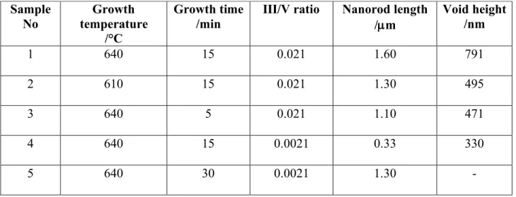
Table 1. Growth conditions for InN nanorods on GaN templates
3. Results and discussion
Figure 1 (a) shows a tilted SEM image of InN nanorods grown for 15 minutes at 640 °C (sample 1). The nanorods grow vertically along the c-axis and exhibit an hexagonal shape defined by six equivalent m-plane side facets and the c-plane facet at the top. A more detailed structural characterization of InN nanorods grown under these conditions was presented in our previous work
[23]. High-resolution transmission electron microscopy revealed that the nanorods are defect-free in
the top part, while some stacking faults can be found in the bottom part near the mask/InN nanorod interface. Vertical cross section of the nanorod is reported in Figure 1 (b). The presence of void of about 791 nm length is clearly seen inside the nanorod. The roughness of the inner surface restricting the void is probably due to thermal decomposition, because this surface is not exposed to the flows, particularly to NH3, which is known to stabilize the facets of InN. Thermal
decomposition of In-N bonds generates liquid indium and N2. During cooling down to room
temperature, the saturated vapor pressure of N2 decreases, which causes random condensation of
InN inside the void. This may result in the void asymmetry, which is seen in Figure 2 (c). Sample No Growth temperature /°C Growth time /min
III/V ratio Nanorod length
/µm Void height /nm 1 640 15 0.021 1.60 791 2 610 15 0.021 1.30 495 3 640 5 0.021 1.10 471 4 640 15 0.0021 0.33 330 5 640 30 0.0021 1.30 -
6
Schwenzer et al. previously reported that thermal decomposition of InN at a higher temperature of 650 °C can lead to the formation of InN nanotubes rather than NWs [27].
Figure 1 (a) Tilted SEM image of InN nanorods grown on Ga-polar GaN/c-Al2O3 template masked
with SiNx and patterned with circular openings of 200 nm in diameter and a pitch of 2 µm. SEM
images taken during the FIB preparation of (b) sample 1, (c) sample 2, and (d) sample 3, showing the void size.
However, thermal decomposition of InN may not be the cause for the void formation in this work. If thermal decomposition was involved, we would expect a more homogeneous decomposition of InN along the entire length of the nanorod rather than only in its lower section. As a matter of fact, additional experiment, where the growth temperature was lowered to 610 °C (sample 2, Figure 1 (c)), has shown a reduction of the void height, which is associated simply with a shorter length of the nanorod and can hardly be attributed to thermal decomposition of InN. As
7
further attested by several experiments under different growth conditions, there is always a relationship between the void height and the nanorod length, that is: longer nanorods have larger voids and this is almost independent of the growth temperature. For example, Figure 1 (d) shows a cross section of InN nanorod grown at 640 °C for only 5 minutes (sample 3). It is clearly seen that the void height shrinks with decreasing the total length of the nanorod regardless of the higher growth temperature. A detailed photoluminescence (PL) study of InN nanorods grown under different conditions is presented elsewhere [30]. In brief, we found that the nanorods are
unintentionally n-doped with a high electron concentration and PL peak energy is blue shifted when the diameter of nanorods decreases. Based on these observations, we forecast that the InN growth proceeds with two modes: as hollow nanotube at the beginning and becoming a full nanorod upon exceeding a certain critical length. Note that the first stage with hollow nanotubes is difficult to observe under the implemented experimental conditions, corresponding to a very high growth rate of InN nanorods of about 220 nm/min.
Figure 2(a) shows a tilted SEM image of InN nanorods grown on Ga-polar GaN/c-Al2O3
templates masked with SiNx at 640 °C for 15 minutes (sample 4). Here, the hole diameter was
increased to 500 nm, while the pitch was increased to 1.5 µm to reduce the fill factor. The axial growth rate was also reduced to ~ 20 nm/min by decreasing the III/V ratio by a factor of 10. This experiment shows very clearly that nucleation of InN crystals occurs preferentially at the hole edges, resulting in the formation of hollow nanotubes after 15 minutes (see the inset in Figure 2(a) for a clearer view). A longer growth time of 30 minutes (sample 5) leads to the formation of InN nanorods with well-defined facets, as seen in Figure 2 (b).
8
Figure 2 Tilted SEM images of InN nanorods grown at 640 oC in the patterned array of 500 nm
diameter holes with a pitch of 1.5 µm, showing different morphologies after (a) 15 minutes and (b) 30 minutes of growth.
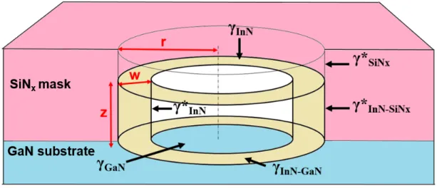
To explain these findings, we have established the following model. The model geometry is shown in Figure 3 and consists of an InN nanotube (ring) grown in a SiNx nanohole on GaN with
variable aspect ratio depending on the nanotube length or, equivalently, on the total volume of InN deposited into the hole. This volume is given by , where is the surface area of the nanotube base of width , is the hole radius and is the nanotube height. The free energy of forming the InN nanotube of width and height in the hole equals
(1) Here, the first term corresponds to the chemical potential decrease due to crystallization of the volume of InN from vapor. The second term describes the elastic energy induced by the lattice mismatch between InN and GaN ( , but the reduced mismatch can be decreased with respect to by misfit dislocations at the InN/GaN interface [31]), with , as
Young’s modulus and as the Poisson ratio of InN, and 7.5 as the relaxation coefficient [31-33]. The next two terms stand for the surface energies of vertical sidewalls of InN, with
Sz V = S=pr2-p(r-w)2 w r z w z ). ( ) ( 2 ) ( 2 / 1 * * * 2 GaN GaN InN InN InN SiN SiN InN r w z S rz w Az V V G µ le + p g -g + p - g + g +g -g + + D -= D - -V e e0 =0.11 e 0 e l= E/(1-n) E n A@ * g
9
representing the surface energies of the corresponding vertical interfaces as shown in Figure 3 (the InN-SiNx interface and InN surface are created and the SiNx surface is eliminated upon the
formation of InN ring). The last term stands for the in-plane surface energy change, with representing the surface energies of the corresponding in-plane interfaces (the InN-GaN interface and InN surface are created and the GaN surface is eliminated upon the formation of InN ring).
Figure 3 Geometry of InN ring inside the GaN/SiNx circular hole, showing the six surface and
interface energies of interest.
Let us now introduce the dimensionless free energy , and the aspect ratio of the InN ring
. (2) Clearly, the geometries with correspond to a nanotube with a hole in the center, while at = 1 InN covers entirely the GaN surface. After some manipulations, Eq. (1) can be presented as a function of
,
(3) where we do not write an unimportant constant. The control parameters are given byg ) /( 2 0V G f =D le r w x= / 1 < x x x ) 2 ( ) 2 ( ) 2 ( ) 2 ( ) ( 2 2 x x v c x x bx a Av x x x x x f + -+ + -=
10
,
,
,
(4) where(5) is the dimensionless volume of the deposited InN. The is the vertical surface energy and is the in-plane surface energy change upon the formation of InN ring in a SiNx/GaN hole. The conditions and correspond to the
sticking of In to the GaN bottom of the hole but not to its SiNx sidewalls.
The preferred geometry of InN is now determined by the minimum of as a function of at a given volume , as in Refs. [34, 35]. At , Eq. (3) describes homoepitaxial growth of
InN far away from the substrate. The limit of corresponds to the initial nucleation of InN on GaN surface according to the Stranski-Krastanov mechanism [36]. At and , both limiting
regimes correspond to planar growth with the energy minimum at . Therefore, InN nucleates in a hole in a planar form, then quickly transforms into a nanoring and continues growing as a nanotube until reaching a certain height, after which the inner hole disappears. This feature corresponds exactly to the growth behavior observed experimentally, and is independent of the parameters provided that and , that is, where InN prefers to stick to GaN rather than the walls of the hole in the SiNx mask layer.
The elastic constants of wurtzite InN are well-known and equal to 308 GPa, 0.23 (Ref. [37]), yielding = 400 GPa. With = 100 nm for the hole radius and 0.11, this gives an estimate of 484 J/m2 for the maximum value of the constant in the denominator of Eqs.
(4). The surface and interface energies and hence the values are less known and can be modified in the presence of the carrier gas and precursors. However, the typical surface energy values are on
r a 2 2* le g D = r b InN 2 * 2 le g = r c 2 le g D = ) /( r3 V v= p * * *
* gInN gInN SiN gSiN
g = + -D -GaN GaN InN InN g g g g = + -D -0 < Dg D
g
*>0 ) (x f x v v®¥ 0 ® v 0 > a c<0 1 = x 0 > a c<0 = E n = l r e @e0= @ r 2 0 le g D11
the order of J/m2 and thus both and values should be much smaller than unity. For example,
Figure 4 shows the graphs of the dimensionless formation energy of InN as a function of the nanotube aspect ratio obtained from Eq. (3) at 0.03, 0.062 and -0.05 for different dimensionless volumes of InN. It is seen that for very small volumes , InN nucleates as thin two-dimensional layer on GaN, corresponding to the energy minimum at . After that, the morphology of InN quickly transitions to a ring-like. The rings first become thinner and then their aspect ratio stabilizes at around 0.3. This geometry yields the formation of InN nanotubes after leaving the holes. However, for sufficiently large distances from GaN, the energy minimum is again at , corresponding to lateral overgrowth of InN and closing the inner hole of nanotube, after which the structures continue growing as nanorods without any void inside.
Figure 4 Graphs of dimensionless energy of InN nanorings in SiNx/GaN templates as a function
of their aspect ratio for different dimensionless volumes of InN from 0.038 to 2 as shown in the insert. InN prefers to nucleate on GaN in two-dimensional form corresponding to the Stranski-Krastanov growth mode (minimum at for 0.038). After that, the minima at are observed, shifting from wider to narrower InN rings (the curves at 0.06, 0.1 and 0.5). After
, corresponding to a void height of 450-500 nm, the influence of GaN substrate becomes negligible and further growth proceeds in the form of full nanorod.
1 a c = a b= c= 06 . 0 < v 1 = x 1 = x r w x= / 1 = x v= x<1 = v 2 @ v
12
More delicate dependences of the void length and morphology on the growth temperature and time should be due to kinetic factors. They are beyond the scope of this work and will be presented elsewhere. However, our considerations reveal the general trend to forming voids in InN nanorods on GaN/SiNx templates due to a large lattice mismatch between InN and GaN in the
bottom of the holes, which disappears at a certain distance from the substrate. The observed phenomenon should pertain for a wide range of the growth conditions and is not specific for HVPE growth. Figure 4 shows a typical behavior where the void closes at a distance of a few hundred nm corresponding to our experimental data. Formation of voids is mainly driven by lattice mismatch with well-defined elastic constants, but also influenced by surface energetics. Starting with Stranski-Krastanow or Volmer-Weber growth at the very beginning, that is, with either a thin wetting layer or three-dimensional islands, is not critical for the follow-up formation of large nanotubes. InN tends to stick to the sidewalls of the SiNx mask openings to minimize the contact
area with GaN surface. According to the model, it is very difficult to substantially increase or decrease the void size for a given material combination (InN on GaN in SiNx mask openings).
Further optimization is required to reduce the surface roughness of the inner sidewalls of InN nanotubes, caused by kinetic processes such as thermal decomposition of InN and its random condensation in the cooling step.
4. Conclusions
In conclusion, we have presented a model based on experimental data to understand the formation of voids in InN nanorods elaborated by selective area growth using hydride vapor phase epitaxy on patterned GaN/c-Al2O3 template masked with SiNx. This model puts emphasis on the
effect of strain induced by the lattice mismatch between InN and GaN. It is shown experimentally and confirmed by the model that the voids form only up to a certain critical length, after which the
13
inside hole disappears at the top and the InN nanotubes become nanorods. Figures 2 clearly demonstrate the possibility to grow either short and open nanotubes of ~ 500 nm height, or longer and closed nanorods with voids inside them. Overall, our growth process produces a rich variety of shapes from nanotubes to nanorods, which can be further optimized versus the growth conditions and time to obtain different InN nanostructures for different applications.
Author contributions
The manuscript was written through contributions of all authors. All authors have given approval to the final version of the manuscript.
Acknowledgements
The financial support received from CNRS (PRC1300 CNRS-JSPS) and from GaNeX program of the French ANR agency (ANR-11-LABX-0014) is gratefully acknowledged. This work was also funded by the program "Investissements d'avenir" of the French ANR agency, the French government IDEX-SITE initiative 16-µIDEX-0001 (CAP20-25), the European Commission (Auvergne FEDER Funds) and the Region Auvergne in the framework of the LabEx IMobS3 (ANR-10-LABX-16-01) and CPER. VGD thanks the Russian Foundation for Basic Research for the financial support under grants Nos.18-02-40006, 19-52-53031, 20-52-16301, and 20-02-00351. The authors gratefully acknowledge financial support of the EPSRC, UK via Grant No. EP/M015181/1, “Manufacturing nano-engineered III-nitrides”. The authors thank also 2MAtech, Aubiere, France for scanning electron microscopy (SEM) measurements.
Corresponding authors
*Mohammed ZEGHOUANE. Institut Pascal, 4 Avenue Blaise Pascal, 63178 Aubière Cedex. France.
14
*Agnès TRASSOUDAINE. Institut Pascal, 4 Avenue Blaise Pascal, 63178 Aubière Cedex. France.
E-mail: agnes.trassoudaine@uca.fr
* Vladimir Dubrovskii. ITMO University, Kronverkskiy pr. 49, 197101 St. Petersburg, Russia E-mail: dubrovskii@mail.ioffe.ru
References
[1] Wu J Q 2009 When group-III nitrides go infrared: new properties and perspectives. J. Appl.
Phys. 106 011101.
[2] Ambacher O 1998. Growth and applications of Group III-nitrides. J. Phys. D: Appl. Phys. 31 2653.
[3] Bhuiyan A G, Hashimoto A, Yamamoto A 2003 Indium nitride (InN): A review on growth, characterization, and properties. Journal of Applied Physics. 94 2779-2808.
[4] Mohammad S N, Morkoc H 1996 Progress and prospects of group-III nitride semiconductors.
Prog. Quantum Electron. 20 361–525.
[5] Mi Z, Zhao S 2015 Extending group-III nitrides to the infrared: Recent advances in InN. Phys. Status Solidi B. 252 1050.
[6] Lye K S, Kobayashi A, Ueno K, Ohta J, Fujioka H 2016 InN thin-film transistors fabricated on polymer sheets using pulsed sputtering deposition at room temperature. Appl. Phys Lett. 109 032106.
15
[7] Hsu L H, Kuo C T, Huang J K, Hsu S C, Lee H Y, Tsai Y L, Su C F, Lin C C 2015 InN-based heterojunction photodetector with extended infrared response. Opt. Express. 23 31150-31162.
[8] Zhao S, Connie A T, Dastjerdi M H T, Kong X H, Wang Q, Djavid M, Sadaf S, Shih I, Guo H, Mi Z 2015 Aluminum nitride nanowire light emitting diodes: Breaking the fundamental bottleneck of deep ultraviolet light sources. Scientific Reports, 5 8332.
[9] Dastjerdi M H T, Boulanger J P, Kuyanov P, Aagesen M, LaPierre R R 2016 Method of Ga droplet consumption for improved GaAs nanowire solar cell efficiency. Nanotechnology, 27 (47) 475403.
[10] Boulanger J P, Chia A C E, Wood B, Yazdi S, Kasama T, Aagesen M, LaPierre R R 2016 Characterization of a Ga-assisted GaAs nanowire array solar cell on Si substrate. IEEE
Journal of Photovoltaics, 6 (3) 661-667.
[11] Goktas N I, Wilson P, Ghukasyan A, Wagner D, McNamee S, LaPierre R. R. 2018 Nanowires for energy: A review. Appl. Phys. Rev. 5 041305
[12] Arafin, Liu 2013 Review of recent progress of III-nitride nanowire lasers. Journal of
Nanophotonics. 3 074599-1.
[13] Lapierre R R, Gibson S J, Rhman K M A 2013 III–V nanowire photovoltaics: Review of design for high efficiency. Phys. Status Solidi RRL 7. 10 815–830.
[14] Li H, Zhao G, Wei H, Wang L, Chen Z, Yang S 2016 Growth of Well-Aligned InN Nanorods on Amorphous Glass Substrates. Nanoscale Research Letters. 11 270.
16
[15] Yang A, Zhang R, Guo Y, Wei H, Zheng G, Yang S 2009 Well-Aligned Zn-Doped InN Nanorods Grown by Metal-Organic Chemical Vapor Deposition and the Dopant Distribution. Crystal Growth & Design, 9 7 3292-3295.
[16] Stoica T, Meijers R, Calarco R, Richter T, Lüth H 2006 MBE growth optimization of InN nanowires. Journal of Crystal Growth. 290 241–247.
[17] Gao F, Wen L, Xu Z, Han J, Yu Y, Zhang S, Li G 2017 Growth of InN Nanowires with Uniform Diameter on Si(111) Substrates: Competition Between Migration and Desorption of In Atoms. Small, 13 21.
[18] Shalish I, Seryogin G, Yi W, Bao J M, Zimmler M A, Likovich E, Bell D C, Capasso F, Narayanamurti V 2009 Epitaxial Catalyst-Free Growth of InN Nanorods on c-Plane Sapphire. Nanoscale Res Lett. 4 532–537.
[19] Simpkins B S, Kansal A D, Pehrsson P E 2010 Induced Epitaxy for Growth of Aligned Indium Nitride Nano- and Microrods. Crystal Growth & Design. 10 9.
[20] Flissikowski T, Brandt O, Grahn H T, Geelhaar L, Riechert H 2011 Suitability of Au- and Self-Assisted GaAs Nanowires for Optoelectronic Applications. Nano Lett. 11(3) 1276– 1279.
[21] Kamimura J, Kishino K, Akihiko Kikuchi A 2010 Dislocation reduction via selective-area growth of InN accompanied by lateral growth by rf-plasma-assisted molecular-beam epitaxy. Appl. Phys. Lett. 97 141913.
[22] Weiszer S, Zeidler A, de la Mata M, Stutzmanna M 2019 Growth of Self-assembled and Position-controlled InN Nanowires on Si (111) by Molecular Beam Epitaxy. Journal of
17
[23] Zeghouane M, Avit G, Cornelius T W, André Y, Bougerol, C, Taliercio T, Ferret P, Gil E, Tournié E, Thomas O, Trassoudaine A 2019 Selective Growth of Ordered Hexagonal InN Nanorods. CrystEngComm, 21 2702-2708.
[24] Coulon P M, Alloing B, Brändli V, Vennéguès P, Leroux M, Zúñiga-Pérez J 2016 Dislocation filtering and polarity in the selective area growth of GaN nanowires by continuous-flow metal organic vapor phase epitaxy, Applied Physics Express. 9 015502. [25] Gacevic Z, Sanchez D G, Calleja E 2015 Formation Mechanisms of GaN Nanowires Grown
by Selective Area Growth Homoepitaxy. Nano Lett. 15 1117−1121.
[26] Schuster F, Hetzl M, Weiszer S, Garrido J A, de la Mata M, Magen C, Arbiol J, Stutzmann M 2015 Position-Controlled Growth of GaN Nanowires and Nanotubes on Diamond by Molecular Beam Epitaxy. Nano Letters. 15 3 1773-1779.
[27] Schwenzer B J, Loeffler L, Seshadri R, Keller S, Mishra U K 2004 Preparation of indium nitride micro- and nanostructures by ammonolysis of indium oxide. Mater. Chem. 14 637– 641.
[28] Wei P-C, Chen L-C, Chen K-H 2014 Surface diffusion controlled formation of high quality vertically aligned InN nanotubes. J. Appl. Phys. 116 124301.
[29] Yin L W, Bando Y, Golberg D, Li M-S 2004 Growth of Single-Crystal Indium Nitride Nanotubes and Nanowires by a Controlled-Carbonitridation Reaction Route. Adv. Mater. 16 20.
[30] Zeghouane M, Avit G, André Y, Taliercio T, Ferret P, Gil E, Castelluci D, Disseix P, Leymarie J, Tournié E, Trassoudaine A 2020 Morphological control of InN nanorods by SAG-HVPE. Crystal Growth & Design. https://doi.org/10.1021/acs.cgd.9b01346
18
[31] Glas F 2006 Critical dimensions for the plastic relaxation of strained axial heterostructures in free-standing nanowires, Phys. Rev. B 74 121302 (R).
[32] Dubrovskii V G, Sibirev N V, Zhang X, Suris R A 2010 Stress-driven nucleation of three-dimensional crystal islands: from quantum dots to nanoneedles Cryst. Growth Des. 10 3949.
[33] Zhang X, Dubrovskii V G, Sibirev N V, Ren X 2011 Analytical study of elastic relaxation and plastic deformation in nanostructures on lattice mismatched substrates Cryst. Growth
Des. 11 5441.
[34] Vukajlovic-Plestina J, Kim W, Ghisalberti L, Varnavides G, Tütüncuoglu G, Potts H, Friedl M, Güniat L, Carter W C, Dubrovskii V G, Fontcuberta i Morral A 2019 Fundamental aspects to localize self-catalyzed III-V nanowires on silicon Nature Comm. 10 869.
[35] Dubrovskii V G 2019 V. G. Geometry of GaAs nanowire seeds in SiOx/Si(111) templates
Mater. Phys. Mech. 42 14.
[36] Liu B, Kitajima T, Chen D, Leone S R 2005 Growth modes of InN (000-1) on GaN buffer layers on sapphire J. Vac. Sci. Tech. A 23 304.
[37] Wright A F 1997 Elastic properties of zinc-blende and wurtzite AlN, GaN, and InN J. Appl.