Design and Evaluation of a Biomimetic
Agonist-Antagonist Active Knee Prosthesis
by
ARCHIVES
Ernesto Carlos Martinez-Villalpando B.S., Electrical and Digital Systems Engineering Universidad Panamericana campus Bonaterra, 2001
S.M., Media Arts and Sciences
Massachusetts Institute of Technology, 2006
Thesis submitted to the Program in Media Arts and Sciences, School of Architecture and Planning,
in partial fulfillment of the requirements for the degree of Doctor of Philosophy
at the
MASSACHUSETTS INSTITUTE OF TECHNOLOGY
June 2012
C Massachusetts Institute of Technology 2012 All rights/reserved
Author: ... ...
Program in Media Arts and Sciences
March 3 0th , 2012
Certified by: ... ...
Hugh Herr, Ph.D. Associate Professor of Media Arts and Sciences and Health Sciences and Technology
A ccepted by: ... ''... ... .... .
Mitchel Resnick, Ph.D. Chair, Department Committee of Graduate Studies Program in Media Arts and Sciences
Design and Evaluation of a Biomimetic Agonist-Antagonist
Active Knee Prosthesis
by
Ernesto Carlos Martinez Villalpando
Thesis submitted to the Program in Media Arts and Sciences, School of Architecture and Planning on March 3 0th 2012 in partial fulfillment of the requirements for the degree of
Doctor of Philosophy
Abstract
The loss of a limb is extremely debilitating. Unfortunately, today's assistive technologies are still far from providing fully functional artificial limb replacements. Although lower extremity prostheses are currently better able to give assistance than their upper-extremity counterparts, important locomotion problems still remain for leg amputees. Instability, gait asymmetry, decreased walking speeds and high metabolic energy costs are some of the main challenges requiring the development of a new kind of prosthetic device. These challenges point to the need for highly versatile, fully integrated lower-extremity powered prostheses that can replicate the biological behavior of the intact human leg.
This thesis presents the design and evaluation of a novel biomimetic active knee prosthesis capable of emulating intact knee biomechanics during level-ground walking. The knee design is motivated by a mono-articular prosthetic knee model comprised of a variable damper and two series-elastic clutch units spanning the knee joint. The powered knee system is comprised of two series-series-elastic actuators positioned in parallel in an agonist-antagonist configuration. This investigation hypothesizes that the biomimetic active-knee prosthesis, with a variable impedance control, can improve unilateral transfemoral amputee locomotion in level-ground walking, reducing the metabolic cost of walking at self-selected speeds.
To evaluate this hypothesis, a preliminary study investigated the clinical impact of the active knee prosthesis on the metabolic cost of walking of four unilateral above-knee amputees. This preliminary study compared the antagonistic active knee prosthesis with subjects' prescribed knee prostheses. The subjects' prescribed prostheses encompass four of the leading prosthetic knee technologies commercially available, including passive and electronically controlled variable-damping prosthetic systems. Use of the novel biomimetic active knee prosthesis resulted in a metabolic cost reduction for all four subjects by an average of 5.8%. Kinematic and kinetic analyses indicate that the active knee can increase self-selected walking speed in addition to reducing upper body vertical displacement during walking by an average of
16%. The results of this investigation report for the first time a metabolic cost reduction when walking
with a prosthetic system comprised of an electrically powered active knee and passive foot-ankle prostheses, as compared to walking with a conventional transfemoral prosthesis.
With this work I aim to advance the field of biomechatronics, contributing to the development of integral assistive technologies that adapt to the needs of the physically challenged.
Thesis Supervisor: Hugh Herr, Ph.D.
Associate Professor of Media Arts and Sciences, and Health Sciences and Technology
Design and Evaluation of a Biomimetic
Agonist-Antagonist Active Knee Prosthesis
by
Ernesto Carlos Martinez-Villalpando
Thesis submitted to the Program in Media Arts and Sciences, School of Architecture and Planning,
in partial fulfillment of the requirements for the degree of Doctor of Philosophy
at the
MASSACHUSETTS INSTITUTE OF TECHNOLOGY
June 2012
0 Massachusetts Institute of Technology 2012 All rights reserved
Doctoral Committee
Committee M ember: ...
Russell Tedrake, Ph.D. Associate Professor Department of Electrical Engineenj and Com cience Committee M ember: ...
DanielF y, Ph.D. Associ e Professor Department of Mechanical Engineering
Acknowledgments
Ad Jesum per Mariam
The work in this thesis was possible thanks to the efforts and contributions of many individuals who deserve my gratitude and recognition. I would like to thank the following individuals, in particular:
My advisor, Prof. Hugh Herr, for all his support and guidance throughout my time at MIT.
The members of the Biomechatronics Group, for their significant contributions to this project over the past years. Particularly, I would like to express my gratitude to Jeff Weber, Grant Elliott, Michael Eilenberg, Bob Emerson, Ken Endo, Jared Markowitz, and Luke Mooney for their invaluable work in the electromechanical designs of the knee prostheses prototypes, and their continual assistance throughout the clinical tests, data analysis, and simulation processes. Bruce Deffenbaugh, for always being there to provide a word of wisdom and direction.
Prof. Daniel Frey and Prof. Russell Tedrake, for their time and guidance throughout my doctoral research.
My labmates and UROPS Andy Marecki, Jacky Lau, Javier Sanchez, Caitlin Reyda, Luis
Carbajal, Claude Lagoda, Andrew Bishara, and Marc Louis for their collaborations in the various phases of the project.
Linda Peterson, Felice Gardner, Tesha Myers and Sarah Hunter, for providing all the necessary resources that enabled my great experience at the Lab.
I would like to thank my family, my parents and sisters for their love and encouragement, and
especially my wife Elizabeth for her love and unconditional support throughout the course of the
Contents
1
IN TR O D UC TIO N ... 102 BA CK G R O UND ... 13
2.1 STATE OF THE ART IN LOW ER EXTREMITY PROSTHESES ... 16
3 K N EE BIO M ECH ANICS ... 19
3.1 INTACT HUMAN KNEE BIOMECHANICS IN LEVEL GROUND W ALKING... 19
3.2 QUASI-PASSIVE PROSTHETIC KNEE MODEL ... 21
3.3 INTACT-SUBJECT W ALKING DATA COLLECTION AND ANALYSIS ... 25
4 M ECH AN ICA L D ESIG N ... 27
4.1 M AIN D ESIGN SPECIFICATIONS ... 27
4.2 M ECHANICAL D ESIGN ARCHITECTURE... 28
4.3 M ECHANICAL D ESIGN D ESCRIPTION ... 29
4.4 M ECHANICAL ANALYSIS ... 40
4.4.1 System m odel...40
4.4.2_Steady state perform ance ... 43
4.4.3 System characterization...45
4.5 ENERGY ECONOMY ... 49
5 CO N TR O L...54
5.1 CONTROL SYSTEM ARCHITECTURE ... 54
5.2 LOW -LEVEL SERVO CONTROLLERS...56
5.2.1 Position controller...56
5.2.2 Im pedance controller ... 56
5.3 FINITE STATE CONTROLLER ... 58
5.4 SENSORS...62
5.5 ONBOARD COMPUTER SYSTEM ... 63
6 CLINICAL EVA LUA TIO N...67
6.1 PRELIM INARY ABLE-BODIED SUBJECT TESTING ... 67
6.2 EVALUATION OF THE ACTIVE KNEE PROSTHESIS WITH TRANSFEMORAL AMPUTEES...69
6.2.1 D ata collection and experim ental protocol ... 70
6.2.2 D ata processing and analysis ... 75
7 RESULTS A ND DISCUSSIO N...77
7.1 W ALKING SPEED...77
7.2 M ETABOLIC COST OF W ALKING ... 78
7.3 JOINT KINEMATICS AND KINETICS...80
7.4 KNEE DAM PING IN SW ING EXTENSION ... 84
7.5 U PPER BODY VERTICAL DISPLACEMENT ... 88
7.6 CONCLUDING REMARKS AND FUTURE WORK...89
BIBLIO G R A PH Y ... 92
List of Figures
Figure 2.1 Amputee walking: relative pace and energy consumption... 15
Figure 2.2 Examples of commercially available knee prosthesis... 17
Figure 3.1 Representative knee biomechanics in level-ground walking. ... 22
Figure 3.2 Variable-impedance prosthetic knee model. ... 24
Figure 4.1 Prosthesis Design Architecture. ... 29
Figure 4.2 Characterization of spring stiffness using Instron@ machine ... 31
Figure 4.3 Mechanical design of the antagonistic active knee prosthesis ... 33
Figure 4.4 Antagonistic motor-transmission assembly... 34
Figure 4.5 Linear carriage/spring enclosure mechanism for series elastic extension actuator... 34
Figure 4.6 Main components of active knee prosthesis (disaggregated view). ... 36
Figure 4.7 Biomimetic agonist-antagonist active knee prosthesis... 38
Figure 4.8 Active knee prosthesis dimensional fit to a model of an average mid-size male su bject... 3 9 Figure 4.9 Schematics of the agonist-antagonist active knee prosthesis. ... 41
Figure 4.10 Knee torque-velocity limits for moderate walking speeds for extension and flexion actu ators ... 4 4 Figure 4.11 Power-velocity limits for moderate walking speed of extension actuator ... 44
Figure 4.12 Experimental Bench-top platform setup for the active knee prosthesis... 46
Figure 4.13 Frequency response: simulation and experimental data for the extension actuator.. 48
Figure 4.14 Agonist-Antagonist, Single SEA and direct-drive architectures for knee active p ro sth esis ... 5 1 Figure 4.15 Active knee prostheses electromechanical architectures comparison... 52
Figure 5.1 General control system architecture of active knee prosthesis... 55
Figure 5.2 Block diagrams for low-level servo controllers ... 55
Figure 5.3 Basic finite- state machine controller for level-ground walking. ... 58
Figure 5.4 Knee damping coefficient during swing extension for able-bodied subjects walking at self-selected speeds. ... 6 1 Figure 5.5 Variable damping profile of the knee joint during swing extension using piece-wise approximation to biological reference trajectory... 62
Figure 5.6 Circuit board assembly of new electronic system main board... 64
Figure 5.7 Program flow through the control framework for the active knee prosthesis... 65
Figure 6.1 Able-bodied wearing active knee prosthesis using kneeling socket. ... 68
Figure 6.2 Average angle vs torque curves of the active knee prosthesis during treadmill walking of able-bodied subject using kneeling-socket adaptor... 68
Figure 6.3 Scope of the active knee finite-state control transitions during level-ground walking. ... 6 9 Figure 6.4 Fitting of active knee prosthesis... 72
Figure 6.5 Unilateral above-knee amputee instrumented with portable K4b2 telemetric system equipm ent for m etabolic cost assessm ent... 73
Figure 6.6 Transfemoral amputee wearing the biomimetic active knee prosthesis, instrumented with reflective markers at the motion capture laboratory ... 74
Figure 7.1 Example of gas exchange rate during walking at self-selected speed for calculating metabolic cost. Highlighted zone represents four minutes of steady-state walking... 79
Figure 7.2 Knee joint biomechanics for subject 1 ... 81
Figure 7.3 Knee joint biomechanics for subject 2 ... 82 Figure 7.4 Knee joint biomechanics for subject 3 ... 83 Figure 7.5 Knee damping coefficient during swing extension phase for each of the three subjects.
... 86 Figure 7.6 Vertical displacem ent of the trunk ... 88
List of Tables
Table 4.1 Series elastic components of extension and flexion actuators... 31
Table 4.2 Active knee prosthesis motor -transmission systems ... 35
Table 4.3 Knee size, angular range, and maximum torque values. ... 38
Table 4.4 Extension and flexion actuator model parameters... 48
Table 4.5 Cost of transport comparison of active knee prostheses electromechanical arch itectures ... 52
Table 5.1 Sensors for the active knee prosthesis ... 63
Table 5.2 Features of the electronic suite system for the active knee prosthesis ... 64
Table 6.1 Amputee participant characteristics... 70
Table 7.1 Self-selected walking speeds with prescribed and active knee prostheses... 77
Table 7.2 Metabolic cost of walking of four transfemoral amputees walking on level-ground at self-selected speed using prescribed prosthetic knees and the active knee prosthesis. ... 78
Table 7.3 Prosthetic system weight distribution... 79
Table 7.4 RMS Error for knee damping coefficient during swing extension phase using the active and prescribed knee prostheses. ... 87
Chapter 1
Introduction
Currently available commercial technologies for lower limb amputees are still far from
providing fully functional replacements of biological legs. Even with the most advanced prosthetic systems available on the market, above knee amputees still exhibit debilitating clinical problems associated with the lack of adequate mobility, such as gait asymmetry, instability, decreased walking speeds and higher energy requirements. In order to solve these problems, the field of biomechatronics has initiated the development of robotic limbs that can emulate healthy leg behavior. This task poses many challenges for researchers as they investigate novel electromechanical designs and control strategies that can adequately integrate with the patient's body and adapt to the patient's mobility needs.
A significant limitation of conventional technologies in leg prostheses is their inability to
provide net positive power output at the joints. This limitation translates into the inability of the prosthesis to restore normal leg functionality and, consequently, in the amputee suffering from clinical problems associated with the lack of mobility and locomotion fatigue. Furthermore, recent development of active powered prostheses has given rise to the pursuit of control strategies that can adequately guide a biological behavior while allowing a more integrated and intuitive human-machine interface.
The biomechanics of normal walking provide a basis for the design and development of new actuated artificial limbs. These prosthetic systems ideally need to fulfill a diverse set of requirements in order to mimic the biological behavior of normal and healthy extremities. In general, some of the main features that should be considered for the design of these prosthetic devices include the capacity to vary stiffness and damping characteristics as well as to provide non-conservative motive power. In addition, these systems must not exceed the weight and dimensional form factor of a comparable intact extremity segment of a healthy/unaffected
person. Moreover, these devices must be adaptive, such that they can change their functional behavior given particular environment disturbances and individual amputees' locomotive needs.
In this thesis, I present the design and implementation of a novel biomimetic active knee prosthesis for transfemoral amputees that is capable of mimicking the behavior of the intact human knee biomechanics. The biologically inspired approach to the design and control of the prosthesis seeks to improve amputees' metabolic requirements, gait symmetry and walking. With this thesis I aim to advance the field of biomechatronics and human-machine integration, contributing to the development of assistive technologies that benefit from the development of biologically inspired models.
The key design architecture and mechanical components of the active knee were established from biomechanical descriptions of the human knee during level ground walking. The knee design is capable of interfacing with conventional prescribed ankle-foot prostheses commercially available. The resulting active knee and ankle biomimetic leg is capable of replicating human-like knee joint mechanics. The active knee presented in this thesis has two main features that contribute to its energetic efficiency: first, it leverages the natural motion dynamics of the leg; second, it uses tendon-like elastic structures to store and release energy, thereby minimizing the power demands on the device actuators.
In order to evaluate the performance and clinical impact of the proposed active leg prosthesis, a series of clinical experiments were conducted with four above-knee, unilateral amputees. This work has been approved by MIT's Committee on the Use of Humans as Experimental Subjects (COUHES). The experiments consisted of three sessions. An initial session qualitatively determined the degree to which the active prosthesis can improve amputee gait. Secondly, an energetic assessment evaluated the impact of the active knee prosthesis on the amputees' metabolic cost of walking and compared the metabolic demand of the prosthesis to that of their prescribed prosthetic technologies. Finally, a biomechanics assessment evaluated joint and motion biomechanics while the amputee walked at self-selected walking speed.
My dissertation work seeks to improve the understanding of the principles of human
locomotion and their application in the development of advanced bionic limbs. Both objectives are aimed to improve the lives of the people with physical disabilities.
This work was possible thanks to funding from the U.S. Veterans Administration under Grant VA241-P-0026 and U.S. Army Medical Research and Materiel Command Award number W81XWH-09-2-0143.
Clinical trials for this work were registered under name: Active Knee Prosthesis Study for Improvement of Locomotion for Above Knee Amputees. National Clinical Trials Registration ID: NCT00771589 (in clinicaltrials.gov).
Chapter 2
Background
In the United States, there are more than 1.7 people living with limb loss (National Limb Loss Information Center 2008). The total number of persons with an amputation and using a prosthesis is expected to reach 2.4 million by the year 2020 (Ziegler-Graham 2008). In the U.S. alone, above knee amputees exceed 300,000 (NCHS99). Every year more than 30,000 transfemoral amputations are conducted in the U.S. (Feinglass, et al. 1999). As a consequence of lower limb loss, patients present several clinical problems, all associated with lack of mobility and higher energetic demands. Even though currently available prosthetic technology provides certain advantages to amputees, it is still limited, as it is incapable of fully restoring intact leg functionality.
For lower limb amputees, one of the major problems associated with reduced mobility is walking fatigue and pain (Postema, et al. 1997). Although the pain felt at the residual limb is due to the behavior of the entire prosthetic system (i.e. from the liner and socket interface to the pylon and the rest of the prosthetic components), it is particularly associated with the coupling between the residual limb and the prosthetic leg. The imperfect coupling allows relative motion between the socket and the femur stump, caused by the compression of the soft tissue. This motion is uncomfortable for the amputee and causes a lack of confidence in applying large forces to the prosthetic leg. In addition, the relatively short moment arm between the hip joint and the socket reduces the force that the hip muscles can apply to the artificial limb (Whittle 1991). Recent advances in socket technology have reduced pain in patients by focusing on cushioning, a primary contributor to comfort. Such technologies cover a large gamut of products, from gel liners and vacuum-assisted sockets to modem interfaces that rely on residual limb laser scanning and computer aided manufacturing. Two particular technologies that have proved to be successful in pain reduction have been shock absorbing pylons and dynamic elastic response (DER) prosthetic feet (Perry 1992). The damping and compliance features they provide have made them popular in most of the commercially available prosthetic systems. Despite their
success in preference among amputees, abnormal gait patterns associated with walking fatigue are still prevalent.
Walking fatigue is synonymous with higher metabolic expenditure and is a common affliction of lower limb amputees. Walking fatigue in lower limb amputees is considerably higher than their matched able body counterparts at comparable speeds. Measures of metabolic expenditures during walking are commonly obtained by analyzing oxygen level consumptions. For unilateral below the knee amputees, the rate of oxygen consumption is 20-30% higher than that of intact subjects (Herbert, et al. 1994) (Molen 1973), and for above knee amputees there is an additional 25% increment (James 1973) (Waters and Mulroy 1999). Conventional prostheses,
despite their damping and compliance features, have not provided a metabolic advantage for amputees (Lehmann, et al. 1993) (Torburn, et al. 1990) (Colborne92) (Huang, Chou and Su 2000) (Thomas, et al. 2000). In addition to higher metabolic consumptions, lower limb amputees show a reduction in their self-selected speed, and in consequence, they present overall diminished endurance.
For above knee amputees, a particular cause of pathological gait is the lack of accurate control of the knee joint during the swing phase. During this phase, the knee cannot be totally free, because it would then extend too rapidly with a sudden stop hitting the boundary in hyperextension. In contrast, the knee joint cannot be so rigid that it does not permit flexion or extension; this would result in an increase of the amount of energy required by the hip muscles to move the prosthesis as a single piece. To prevent these extreme cases, several prosthetic knees have been developed that include friction mechanisms and hydraulic/pneumatic systems, with some of the most advanced systems having electronic control technologies. Some have been designed as variable damping devices that change their behavior depending on the joint angle, speed and direction of motion. These mechanisms have partially solved some of the problems associated with abnormal gait patterns in amputees (Whittle 1991).
A major cause of abnormal gait for transfemoral amputees is the need to walk with the
knee in full extension during the single stance support phase, since the amputees cannot provide opposition to an external flexion torque around the knee axis. To prevent this, passive artificial
knees with higher stiffness are generally employed. However, the inconvenience with higher stiffness in the knee joint during the stance phase is that the location of the center of gravity is dramatically affected, increasing the energy needed to walk. Although amputees adapt to this circumstance, this type of walking is energetically demanding for all of patients (Whittle 1991).
CU)
0M
w C
a)L
TP HD TF KD TT Intact
* Walking Speed
0
Net Energy Cost
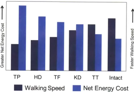
Figure 2.1 .Amputee walking: relative pace and energy consumption( (Rose and Gamble 2006)
from modified data in (Waters and Mulroy 1999)). Representation of two important trends that compare the relative pace and energy consumption for amputees walking with a lower limb prosthesis. The higher the level of the amputation the slower the self-selected walking speeds becomes in addition to larger net energy required to walk a given distance. TP= tanspelvic amputation; HD= hip disarticulation amputation; TF = transfemoral amputation; KD= knee disarticulation amputation; TT= transtibial amputation; Intact= non-amputee.
For below the knee amputees, the inability to articulate their ankle joint generates an abnormal gait, including gait asymmetries, lower self-selected speeds and higher energy requirements (WinterSienko88) (Molen 1973) (Colborne92). The human ankle joint is essential to walking, as it provides a significant amount of net positive work over the stance period of walking, especially at moderate to fast walking speeds (Winter 1983) (Palmer 2002) (Gates 2004). Since the below the knee amputee cannot actively plantarflex at the end of the stance phase of walking, no power is generated in the push off. The amputee must therefore lift the leg sooner to clear the ground, since the effective length of the leg is reduced compared to a normal limb. There are some commercial prostheses that have a spring-like behavior that help store
some energy during hill strike and stance phase and then release it at toe-off. Although these prostheses have a certain spring-like give which helps them function as initial and terminal rockers, they cannot provide net positive work; as a result, they are not functional enough to replicate a normal ankle's flexibility and actuation (Whittle 1991).
2.1 State of the Art in Lower Extremity Prostheses
Modem transfemoral prostheses can be classified into three major groups: passive, variable-damping, and powered. Passive prosthetic devices do not require a power supply for their operation, and are generally less adaptive to environmental disturbances than variable-damping or powered prostheses.
Variable-damping knees have been some of the most significant advances in active prostheses technology. These knees require a power source to modulate damping levels and adapt to different modes of gait, whereas powered prosthetic knees are capable of performing non-conservative positive work. Variable-damping knees offer several advantages over mechanically passive designs, including enhanced knee stability and adaptation to different ambulatory speeds (Flowers 1972) (Stein, Rolf, James, & Tepavic, 1990) (Kitayama, Nakagawa and Amemori 1992) (Herr and Wilkenfeld 2003) (Johansson, et al. 2005)(Zahedi 1993) . Examples of commercially available variable-damping knees include the Blatchford Endolite Intelligent Prosthesis, the Otto Bock C-leg, and the
Ossur
Rheo.From these examples, two of the most advanced devices, and the most relevant to the current investigation, are the Otto Bock's C-leg and Genium models. These knees use a microcomputer to adjust the damping characteristics of their hydraulic joint in order to adapt to patients' walking speed and to detect and prevent stumbling, allowing safer ramp and stair descent. A second example of a microcontroller based knee is the Ossur's Rheo Knee, developed originally at MIT. This knee prosthesis actively controls a magnetorheological-based fluid that varies damping ratios to allow speed and terrain adaptation.
Although variable-damping knees offer some advantages over purely passive knee mechanisms, they are nonetheless incapable of producing positive mechanical power and therefore cannot replicate the positive work phases of the human knee joint for such activities as sit-to-stand maneuvers, level-ground walking, and stair/slope ascent ambulation. Not surprisingly, transfemoral amputees experience clinical problems when using variable-damping knee technology. For example, amputees have asymmetric gait patterns, slower gait speeds, and
elevated metabolic energy requirements compared to non-amputees (Johansson, et al. 2005).
a) b) c)
Figure 2.2. Examples of commercially available knee prosthesis. According to their classification from left to right: a) Passive: Ossur@ Total Knee and Endolite® Mercury; b) Variable-damping: Ossur@ Rheo knee and Otto-Bock® C-leg; c) Powered: Ossur@ Power Knee.
A challenging design problem has been developing a commercially-viable powered
prosthesis that is human-like in its weight, size and strength while still being energetically economical and noise-free. Current approaches to the design of powered prostheses have focused mainly on the use of single motor-transmission systems directly coupled to the knee joint (Kapti and Yucenur 2006) (Fite, Mitchell and Goldfarb 2007). (www.ossur.com) Such direct-drive designs, however, require high electrical power consumption to emulate fully the mechanical behavior of the human knee joint even during level-ground ambulation. Perhaps one reason for this lack of energetic economy is that such designs do not adequately leverage the passive dynamics of the leg, and the elastic energy storage and return of tendon-like structures, in a manner comparable to highly economical walking machine designs (McGeer, 1990) (Wisse
2004) (Endo, Paluska and Herr 2006) or simpler mechanical knee designs with extension assist compliant elements (Radcliffe 1977).
The development of powered foot-ankle prostheses for transtibial amputees is less far advanced. Ossur has introduced the first commercially available "powered" ankle prosthesis named "Propio Foot," which does not provide net power during the gait. Instead, it can actively adjust the dorsiflexion angle to avoid stumbling during walking and to allow a better sitting posture (Koniuk 2001). Au and Herr at MIT introduced the world's first powered foot-ankle system capable of providing an improved metabolic economy to below-knee amputees. This prosthesis is capable of both varying joint impedance during stance and providing sufficient instantaneous power output and torque during push-off in order to propel the amputee during level-ground walking (Au, Martinez-Villalpando and Herr, Powered Ankle-Foot Prosthesis for the Improvement of Amputee Ambulation 2007) (S. Au 2007) (Au and Herr 2008). Hitt et al have built an active robotic ankle prosthesis with anterior-posterior and medio-lateral actuation (Hitt, et al. 2006). Collins and Kuo introduced controlled energy storage and release prosthesis (CESR) for below knee amputees, capable of efficiently storing energy during stance and adequately timing its release in order to help amputees improve their gait (Collins and Kuo 2010). Transfemoral prostheses that include both powered knee and ankle system are limited. Sup et al have built a tethered, electrically powered knee and ankle prototype (Sup, Bohara and Goldfarb 2008) and more recently presented an electrically powered self-contained active and ankle prosthesis (Sup, Varol, et al. 2009).
Chapter 3
Knee Biomechanics
In this chapter, the human knee biomechanics for level ground walking are reviewed. Based on the biomechanical functional description of the intact knee joint, a mono-articular variable-impedance prosthetic knee model is presented. This model is then used to motivate the
electromechanical design architecture of the active knee prosthesis.
3.1 Intact human knee biomechanics in level ground walking
In order to inform the design of the active knee prosthesis, it is important to study the biomechanics of the intact human knee joint. Human walking is a periodic behavior, and its representative period is called a gait cycle (GC). For level-ground walking, the gait cycle is commonly defined as the period between successive heel-strikes of the same extremity. The GC has two main phases: stance and swing. Stance phase, defined as the period in which the foot of the observed extremity is on the ground, takes approximately the first 60% of GC, and the swing phase (while the foot is off the ground) takes the rest. Both of these phases can be divided into subphases. In the following section, I describe the main subphases in the GC, focusig on the biomechanical description of the knee joint. For the purposes of this thesis, the analysis and description of the knee behavior consider only the sagittal plane.
Five distinct stages or gait phases have been used to describe knee biomechanics in level-ground walking: (see figure 3-1):
1. Stance Flexion. Beginning at heel strike (HS), the knee begins to flex slightly (15 degrees).
2. Stance Extension. After maximum stance flexion (MSF) is reached, the knee joint begins to
extend (15% gait cycle), until maximum stance extension (MSE) is reached (42% gait cycle).
3. Pre-Swing. Occurring in late stance (from 42% to 62% gait cycle), the knee of the supporting leg begins its rapid flexion period in preparation for the Swing phase. The knee begins to flex in preparation for toe-off.
4. Swing Flexion. As the hip is flexed, the leg leaves the ground and the knee continues to flex.
At toe-off, the Swing Flexion phase of gait begins. Through this period (from 62% to 73% gait cycle), knee power is generally negative as the knee's torque reduces knee rotational velocity.
5. Swing Extension. After reaching a maximum flexion angle (-60 degrees) during Swing, the
knee changes direction and begins to extend. During Swing Extension (from 73% to 100% gait cycle), knee power is generally negative to decelerate the swinging leg in preparation for the next stance period. After the knee has reached full extension, the foot, once again, is placed on the ground, and the next walking cycle begins.
From the biomechanical description of the knee in each of this subphases, a general model description of the knee behavior is extracted. This modeled behavior can be divided again in the two main phases of gait, stance and swing.
During stance flexion-extension and pre-swing, the knee can be modeled with spring-like elements (observe the torque vs. angle slope in figure 3-1B). In stance flexion, a linear elastic element stores energy in preparation for the Stance Extension. In stance extension, the knee continues to behave as a spring with similar stiffness' to that of Stance Flexion. Furthermore, in pre-swing, as the knee flexes in preparation for toe-off, the spring-like behavior of the knee is maintained but with relatively lower stiffness as compared to Stance Flexion and Extension.
After toe-off and throughout swing, knee power is predominantly negative. During swing flexion the knee torque reduces knee rotational velocity before reaching a maximum knee
flexion angle. After changing direction, and as the lower leg extends, knee power is mainly negative, decelerating the swinging leg and reducing terminal impact in preparation for the next heel-strike that starts the new gait cycle. Knee behavior during swing flexion and extension phases exhibits a predominant negative joint power, thus allowing this behavior to be captured primarily with a variable damper.
3.2 Quasi-passive prosthetic knee model
Given the knee biomechanics descriptions and model insights from the last section, we anticipate that a variable-impedance knee prosthesis, capable of varying both damping and stiffness, can produce human-like knee mechanics during steady-state level-ground walking. As a first evaluation of this hypothesis, and to motivate the design of the prosthesis, a prosthetic knee model is proposed (shown in figure 3.2), comprising two antagonistic series-elastic clutches (to model the stance phase knee mechanics) and one variable-damping element (to model the swing phase mechanics). In the model, a series spring can be engaged by activating its respective clutch, or disengaged by opening that clutch. A constraint of the model is that each clutch can be engaged only once during each gait cycle. Additionally, once a clutch has been engaged, it only can be disengaged when the series spring has released all its energy and the force on the clutch is zero.
80[ A 60[ 040 200 0% -2% 20 40 60 80 100 40 MSE 60F2 Swing Extension 40 t E HS , O E20i MWF e 0 r-20tsCycle __,
F Extension wance Swing in
sace extesion TOn toFffadeWxaiumsinolein
K-20 .40Flexion -40 MSF -601 -6 0 08 Angle (deg) 100 50 0 0-.3' -50. -100 -15 - --20 40 606 8-0 -1100 Gait Cycle (%)
Figure 3. 1- Representative knee biomechanics in level-ground walking. In (A), the knee angle, torque, and power curves of a mid-size average male subject (mass = 81.9 kg) are plotted against percent gait cycle during level ground walking at a self selected speed (1.31 m/sec). Plotted are mean (solid line; N=1 0 gait trials) about one standard deviation (dashed lines). In (B), knee torque is plotted vs. knee angular position showing the five phases of gait. Key gait events
separating the five phases are: HS, heel strike; MSF, maximum stance flexion; MSE, maximum stance extension; TO, toe off; and MWF, maximum swing flexion.
We varied series-elastic clutch model parameters: two spring constants (kE, kF)
corresponding to the extension2 and flexion spring stiffness, and the relative knee extension and flexion equilibrium angles (OE and 0F) at which the extension and flexion springs engage
during stance.
The knee model was fitted to biomechanical data using an optimization scheme that minimized the sum over time of the squared difference between the model's knee joint torque
and biological knee values. More specifically, the cost function used for the optimization was
ECOSt (kFk E,(F 1E )=100 (Ti m
1
(3.1)I OEF rb sm
bio )
where r ibo and r isim are the angular torques applied about the knee joint at the ith percentage of
gait cycle from the biological torque data and the knee model, respectively, and r"axbio is the maximum biological torque at the joint during the gait cycle. Cost function (1) was minimized with the constraint that the extensor spring always engages at heel strike (OE = 0). We applied
this constraint to limit knee buckling at heel strike as a safety measure for the amputee. The determination of the desired global minimum for cost function (1) was implemented by first using a standard genetic algorithm (gatoolbox MATLAB@) to find the region containing the global minimum, followed by an unconstrained gradient optimizer (fminunc function application in MATLAB@) to determine the exact value of that global minimum. After optimizing cost function by varying the parameters of the series-elastic clutch elements, the model's variable damper was used to achieve perfect agreement between the prosthetic knee model and biological torque values in regions where the series-elastic components were not able to absorb sufficient negative mechanical power.
The biological knee torque values were obtained from an inverse dynamics calculation using kinetic and kinematic data from ten walking trials of a healthy subject (81.9 kg, 1.87m in height walking at 1.31 m/s). The subject was chosen as a representative mid-size average male that fits the 50% percentile description for US adults (Tilley, A R; Henry Dreyfuss Associates
2 By convention, the extensor spring tends to extend the knee joint when engaged, whereas the flexor spring tends to
2002). A detailed description of how these kinetic and kinematic data were collected and analyzed is presented in the next section, Intact-subject walking: data collection and analysis.
-4W- Spring Clutch Variable Damper 60 8 100 20 40 60 Gait Cycle(%) 80 100
Figure 3.2- Variable-impedance prosthetic knee model. The model, shown on the right, comprises two mono-articular series-elastic clutches and a variable-damping element. In the upper plot, optimized net torque output of the knee model (red line) is compared to the torque profile of an intact human knee joint (mean is solid blue line; one standard deviation is dashed blue line; N=10 gait trials). Biological data, adopted from figure 3.1, are from a study participant (mass = 81.9kg) with intact limbs walking at a self-selected speed (walking speed = 1.31 m/sec).
Shown in the lower plot are the torque contributions from the extension (red line) and flexion (blue line) springs of the series-elastic clutch elements, as well as the variable damper (green line). The optimizer gave an extension spring stiffness equal to kE =160 N.m/rad, a flexion spring stiffness equal to 137 N.m/rad, and a knee engagement angle for the flexion spring equal to 0.27 radians (15.46 degrees). The extension spring was constrained to engage at the instant of heel strike. E z2 E z U, C 0 (ri C
Figure 3.2 shows the model optimization results plotted against the biological torque data from figure 3.1. The model's torque output agrees well with experimental values. As constrained by the optimization procedure, the extension spring engages at heel strike, storing energy during early stance knee flexion. As the knee begins to extend, the flexion spring is engaged, storing energy as the extension spring releases its energy. During the swing phase, the model's variable damper exactly matches the biological torque values in regions of negative power. At mid and terminal swing phase, the power is positive in the biological data, and thus, the damper outputs zero torque in these gait regions.
3.3 Intact-subject walking data collection and analysis
Intact-subject kinetic and kinematic walking data were collected at the Gait Laboratory of Spaulding Rehabilitation Hospital, Harvard Medical School, in a study approved by the Spaulding committee on the Use of Humans as Experimental Participants. One healthy male adult participant volunteered for the study. The participant was asked to walk at a self-selected speed across a 10m walkway in the Motion Analysis Laboratory, for ten consecutive trials. He was timed between two fixed points to ensure that the same walking speed was used between experimental trials. Walking speeds within a ±5% interval from the self-selected speed were accepted. The data collection procedures were based on standard techniques (Winter D. , 1990)(Kadaba, Ramakrishnan and Wootten 1990). An infrared camera system (eight cameras,
VICON 512 motion analysis system, Oxford Metrics, Oxford, UK) was used to measure the
three-dimensional locations of reflective markers at 120 frames/s. A total of 33 markers were placed on various parts of a participant's body using the standard Plug-in Gait model: 16 lower-body markers, five trunk markers, eight upper-limb markers and four head markers following. The markers were attached to the following bony landmarks: bilateral anterior superior iliac spines, posterior superior iliac spines, lateral femoral condyles, lateral malleoli, forefeet and heels. Additional markers were rigidly attached over the mid-femur and mid-shaft of the tibia. The kinematics of the upper body were also collected with markers placed on the following locations: sternum, clavicle, C7 vertebra, T1O vertebra, head, and bilaterally on the shoulder,
elbow and wrist. The VICON 512 system was able to detect marker position with a precision of
~1mm.
During walking trials, ground reaction forces were measured synchronously with the kinematic data at a sampling rate of 1080Hz using two staggered force platforms (Advanced Mechanical Technology Inc. -AMTI, Watertown, MA, USA) embedded in the walkway. The platforms measured ground reaction force and center of pressure location at a precision of -0.1N and -2mm, respectively. Prior to modeling and analysis, all marker position data were low pass filtered using a 4th order digital Butterworth filter at a cutoff frequency of 8Hz. Filter frequency
was based on the maximum frequency obtained from a residual analysis of all marker position data, and processed as one whole gait cycle with 100 discrete data points from the heel strike to the next heel strike of the same leg. Joint torques and powers were then calculated using a standard inverse dynamics model (Vicon Bodybuilder; Oxford Metrics, UK).
Chapter 4
Mechanical Design
Developing a powered prosthesis that is human-like in weight, size and functionality, while still being energetically-efficient and noise-free, is indeed a challenging task. Current approaches to the design of powered prostheses have focused mainly on the use of single motor-transmission systems directly coupled to the knee joint (Kapti and Yucenur 2006) (Fite, Mitchell and Goldfarb 2007) (www.ossur.com). Such direct-drive designs, however, require a high electrical power consumption to emulate fully the mechanical behavior of the human knee joint even during level-ground ambulation. One reason for this lack of energetic economy, perhaps, is that such designs do not adequately leverage the passive dynamics of the leg and the elastic energy storage and return of tendon-like structures in a manner comparable to highly economical walking machine designs or simpler mechanical knee designs with extension assist compliant elements (Radcliffe 1977).
From the biomechanical knee descriptions and gait biomechanics, the main design goals for the prosthesis that should be considered are categorized as follows.
4.1 Main Design Specifications
Size and weight. The overall design of the knee prosthesis considers the dimensions of
average mid-size U.S. male subject that fits the 50% percentile anthropometric dimensions and weight distribution ( (Tilley, A R; Henry Dreyffus Associates, 2002) (Winter, Biomechanics of Motion of Human Movement 2005)). For this average subject, intact lower leg length measured from the femoral condyles to medial malleoulus corresponds to an average of 42.2 cm. Taking into account socket for the residual limb, as well as standard distal and proximal prosthetic knee connectors and adaptors to the socket and foot-ankle prosthesis the design goal criteria for knee
prosthesis' length is a maximum of 35 cm. The biological segment of lower extremity based on the same landmarks mentioned earlier is on average 4.65% of body weight according to body segment estimates obtained from (Winter, Biomechanics of Motion of Human Movement
2005) (Durkin and Dowling 2006). The prosthesis, considering an average intact male subject,
should not exceed a total mass of 3.6 kg. Furthermore, the electromechanical structure of the knee should remain within the biological volumetric envelope of the biological counterpart for aesthetic symmetry purposes.
Flexion and extension range. In level-ground walking from slow to fast speeds, the knee
angle does not surpass 650 of flexion (during maximum swing flexion) (Winter D. A., 1983). However, the design of the knee should consider other activities with higher flexion angles such as sitting/standing maneuvers and stair ascent/descent where the maximum observed knee flexion angle is can reach up to 1050 (Riener, Rabuffetti and Frigo 2002). The knee prosthesis then should accommodate such flexion angle range.
Joint output torque. For an average able body intact subject walking from slow to fast
speeds on level-ground, requires an average maximum knee torque of 60 N.m (Winter D. A.,
1983). However for stair ascent and descent, larger torques are required. A maximum of
approximately 120 N.m for a mid-size subject in stair descent is measured (Riener, Rabuffetti and Frigo 2002) . We used this value as the target output torque specification for the active knee design. Moreover, the motion bandwidth of the knee in level ground walking should have at least a bandwidth of 2 Hz. This value is an average observed in intact humans at moderate self-selected walking speeds (Winter D. A., 1983).
4.2 Mechanical Design Architecture
Motivated by the prosthetic knee model described in Chapter 3, a novel active knee prosthesis design architecture is proposed. This novel design is a result of earlier work developed
by the author at the Biomechatronics Group (Villalpando and Herr 2009;
This active knee prosthesis is comprised of two actuators arranged in parallel with agonist-antagonist architecture. Each of the two actuators provides an independent extension and a flexion motion respectively. The extension actuator is bidirectional, and the flexion actuator is unidirectional. Each actuator of the knee prosthesis consists of a motor and a series-elastic element, connected via a transmission. The extension and flexion actuators can be used independently to control the knee angle. Because of its architecture, this knee architecture can be controlled in order to behave with a clutchable series elasticity during the stance phase, and as a variable-damper during the swing phase. This design architecture is hypothesized to serve as a basis of a knee prosthesis that is energy efficient for level-ground walking.
Figure 4. 1- Prosthesis Design Architecture. A simplified mechanical schematic of the
agonist-antagonist knee.
It is important to note that since the knee design is fully motorized, knee joint torque can
be directly controlled for more energetically expensive tasks, such as ascending stairs or inclined
terrains, as well as standing from a seated posture. Hence, the knee architecture is designed to accommodate non-conservative, high mechanical power movements, while still providing for a
highly economical level-ground walking mode.
4.3 Mechanical Design Description
4.3.1 Series Springs - The flexion and extension springs for the knee prosthesis were selected based on the knee model optimization values performed in chapter 3. These springs
were selected in in order to accommodate a knee design for an average mid-size U.S. male subject (50% percentile). The selected moment arm from each actuator to the output joint is of
2.54 cm (equivalent to 1 in). This moment arm matches the distance from knee joint rotation axis
to socket pyramid connector seen in other commercial prosthetic devices. Given the maximum angular displacement the knee joint exhibits during stance while walking at fast speeds (Winter
D. A., 1983), (faster walking speeds exhibit greater joint displacements) we estimated the
maximum compression of such springs. This allows us to determine their minimum length in order to choose a spring that can maintain an ideal operating range.
According to data presented in (Winter D. A., 1983), the maximum knee flexion in stance during fast walking is ~190 and the maximum knee extension is ~150. We assume the extension and flexion springs can be engaged through the whole range of those flexion and extension motions respectively. With a 2.54 cm moment arm, the maximum linear displacement of the springs is of 0.84 cm and 0.66cm for the extension and flexion springs respectively. Generally a spring cannot be compressed more than 40% of their free length in normal operation, particularly those that are meant for medium to high duty applications. With this constraint, the minimum desired length for such springs should be of 2.15 cm for the extension spring and 1.65 cm for the flexion springs.
The series springs selected for the extension and flexion actuators are both commercial helical coil compression die springs (linear). The extension actuator has two pre-compressed identical spring in a typical bidirectional series elastic actuator (described in the next section). These springs are Century's spring @ model D-52, medium duty oil-tempered steel spring with nominal free length of 1 in (2.54 cm). The flexion actuator has a single spring element, Lee spring@ LHL 1OOC 01 heavy duty die spring with nominal free length of 1 in (2.54 cm)
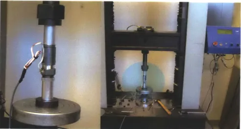
A characterization of those springs was performed using an Instron@ machine in order
to verify their stiffness values and calibrate sensor readings. A summary of their specifications is shown in table 4.1.
Figure 4.2- Characterization of spring stiffness using Instron@ machine Series Elastic Spring Element Simulation Stiffness Manufacturer-Model Nominal
Extension (x2) 248 kN/m Century Spring @ 252 kN/m 258 KN/m
(160 Nm/rad) D-52 (162 Nm/rad) 166 Nm/rad
Flexion 212 kN/m Lee Spring® 192 kN/m 224 KN/m
(137 Nm/rad) LHL
1000C
01 (124 Nm/rad) (145 Nm/rad)Table 4.1 . Series elastic components of extension and flexion actuators
4.3.2 Actuator and Transmission - The flexion and extension actuators system should be capable of providing the desired torque-velocity trajectories during level ground walking, ensuring that the motors in the system will not saturate. Thus, the desired knee behavior should remain within the ideal actuator bounds. We characterized the maximum limit performance for both knee actuators during steady state in order to verify their performance and confirm the selection of the motor/transmission system elements.
The extension actuator is bidirectional, and the flexion actuator is unidirectional. The extension actuator and flexion actuator can be used independently to control the knee joint angle at which the series springs can be engaged.
Extension Actuator
The extension actuator, proximal to the knee joint of prosthesis, consists of an extension motor and a set of two pre-compressed series springs, connected via a two stage transmission. The extension transmission consists of a timing pulley set and belt drive system coupled to a precision ball-screw drive.
The extension actuator's electric motor is a brushed 24 V DC motor (Maxon@ RE30). In the first stage of the transmission, the extension motor directly drives a timing pulley-belt drive mechanism. This mechanism has a 1:2.66 transmission ratio. In a second stage, the timing pulley-belt drive mechanism actuates the rotation of a ball-screw (Nook @industries, 10 x 3 mm). When the ball-screw of the extension actuator rotates, there is a linear displacement of the coupled ball-nut support. The ball-nut support is directly attached to the extension series-elastic spring enclosure. The total transmission ratio after the dual stage is of R= 134.8 .
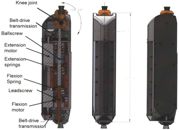
Knee joint Belt-drive transmission Ballscrew Extension motor Extensio springs Flexion Spring Leadscrew Flexion motor Belt-drive transmissio
Figure 4.3-Mechanical design of the antagonistic active knee prosthesis
The extension series-elastic spring enclosure securely contains a spring set of the two identical pre-compressed passive mechanical springs. Their stiffness closely matches that of the model's extension actuator. Thus, when there is a linear displacement of the coupled ball-nut support, the extension series elastic enclosure/cage has a linear displacement. The ball-nut support moves along two custom linear steel guide rails. Each of the rails is attached to a corresponding lateral wall housing. The spring cage moves along the guide rails supported by its incorporated roller bearings. The extension actuator is directly coupled to the rotary motion of the knee joint as it is attached to the steel cable drive system.
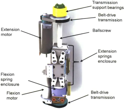
Transmission support bearings Belt-drive transmission Baliscrew Extension springs enclosure Belt-drive 0' transmission
Figure 4.4-Antagonistic motor-transmission assembly
Spring enclosure top cover Extension spring Spring enclosur~e terminal Cable fastener Extension spring oiler bearings Bearing tension adjusters
Figure 4.5-Linear carriage/spring enclosure mechanism for series elastic extension actuator.
Extension motor Flexion spring enclosure Flexion motor 4
Flexion Actuator
The unidirectional flexion actuator of the knee prosthesis consists of the flexion motor and a series spring, connected via a transmission. The flexion transmission also has a dual stage. The first stage consists of a timing pulley set and belt drive system coupled to second stage consisting in a lead-screw drive.
The flexion actuator's electric motor is a brushed 24 V DC motor (Maxon® RE30) similar to the extension actuator. The flexion motor directly drives a timing pulley-belt drive mechanism with a 1:2.66 transmission ratio. The pulley-belt drive mechanism actuates the rotation of a lead-screw (Nook® industries, 10 x 3 mm). The rotation of the lead-screw causes a linear displacement of the coupled ball-nut support that directly attaches to the single flexion series spring enclosure or cage. This cage securely contains the flexion spring. The stiffness of this spring is closely matches that of the model discussed in Chapter 3. The ball-nut support moves linearly along two linear steel guide rails supported with low-friction roller bearings incorporated in the ball-nut support. The flexion actuator is not directly coupled to the rotary motion of the knee joint; however, it can flex the knee when in action, back-driving the extension's series elastic spring enclosure.
Actuator Motor Transmission reduction R = 134.8
Stage 1 Stage 2
Flexion Unidirectional Brushed 24 V SDP Belt- Nook@ Lead-screw
Maxon@ RE30 Drive [10 x 3 mm] [ 1: 2.66]
Extension Bidirectional Brushed 24 V SDP Belt- Nook® Ball-screw
Maxon@ RE30 Drive [10 x 3 mm] [1:2.66]
Table 4.2. Active knee prosthesis motor -transmission systems
The knee electromechanical design can accommodate more powerful motors, including brushless DC motors for the extension and flexion actuators (such as Maxon® EC-powermax 30
and 22) in substitution for the DC motors currently used. This modification would require a change in the electronics suite in order to drive such motors. With brushless motor technology, the knee can reduce its overall weight and increase its torque/power capabilities. The author decided to use a DC motor for this design in order to simplify the electronics requirement and evaluate the clinical impact of the prototype. Once this impact is established, the decision to pursue the installation of different motor technology could be evaluated.
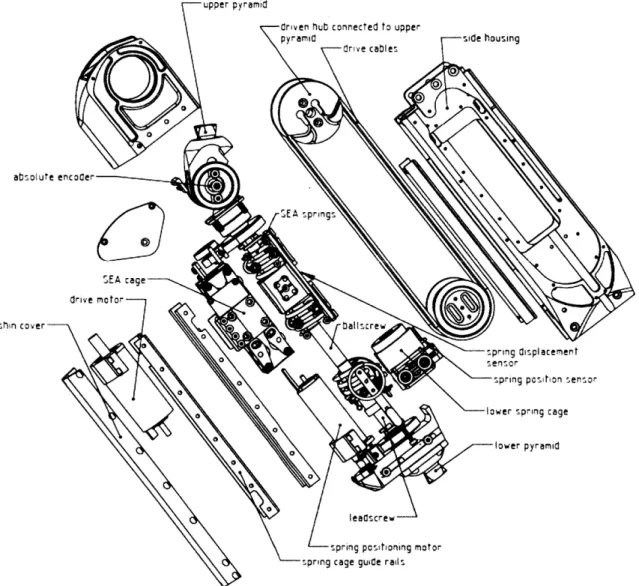
upper pyramid
Criven %ub connected to upper
pyramid side housing
dr ve cables
00
0
0
shin cover ballscre
0-spring displacement
* O senisor
0 spring posihon sensor
sprsg cage guide ra
Figure 4.6- Main components of active knee prosthesis (disaggregated view).
The knee
joint
is rigidly coupled to a set of two steel cable drives connected to the extension's series elastic spring cage. The series elastic cage is supported and guided by two steel precision guide rails. The steel cables allow the coupling of linear displacement from the serieselastic spring enclosure to the rotary motion of the knee joint. The two ends of each of the steel cables are attached to the knee joint's driving hubs. The driving hubs are supported by the knee joint housing. Each cable loops around its corresponding joint pulley located on each side of the knee, distally from the knee joint. Each lateral joint pulley has its axis attached to its corresponding lateral wall. Each cable drive can be independently tensioned with an adjustment to the lateral joint pulley via the tuning of a corresponding cable tensioner.
All actuation mechanisms are fully supported by an aluminum structure that acts as a
chassis composed of the lateral knee walls, a distal pyramid adaptor and a proximal pyramid adaptor. This structure provides a support frame that resembles and fits within the lower limb anatomical volumetric envelope. The lower pyramid adaptor of the knee allows for conventional and advanced robotic foot-ankle prosthesis to be attached. The standard prosthetic upper pyramid adaptor (proximal connector) allows the knee prosthesis to be securely attached to a regular transfemoral socket with standard adaptors worn by amputees. The design of the prosthesis facilitates maintenance, having the chassis include detachable lateral and frontal covers that allow easy access to internal actuators and mechanisms.
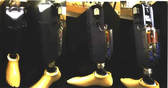
The fully assembled system is depicted in the following images. This system includes a custom electronic system suite integrated in the posterior section of the knee joint (described in the next chapter).
Figure 4.7-Biomimetic agonist-antagonist active knee prosthesis
Specification Intact healthy Active knee
limb prosthesis
Length 35cm 30.9 cm
Medio-lateral width 11cm 6.6 cm
Anterior-posterior width 14cm 7.0 cm
Total weight 3.5kg 2.7 Kg
Flexion angle range 0-1050 0-1250
Maximum output torque 120 N.m 130 N.m
Torque bandwidth 2 Hz 12-14 Hz Table 4.3 Knee size, angular range, and maximum torque values.
Figure 4.8-Active knee prosthesis dimensional fit to a model of an average mid-size male subject.
4.4 Mechanical Analysis
4.4.1 System Model
The antagonistic knee prosthesis can be represented by a linear lumped-parameter model. The model for each of its actuators is based on the series elastic actuator (SEA) representation (Pratt and Williamson 1995). The motor is modeled as a torque source acting on its motor inertia Imotor and motor damping bmotor. The motor is modeled in series with a spring of rotary stiffness
Ks through a transmission of ratio R.
The equivalent motor inertia Me and equivalent damping be described after the transmission drive of ratio R can be approximated as: Me ' Imotor R2 and be ~ bmotor R, respectively.
The model of the SEA's torque output To, provided a requested (input) torque Treg can be approximated as a second order system. The effective requested torque Te that considers the transmission R can be expressed as Te=TreqR where Treq can be related to motor requested current
ireq and the motor torque constant K, through the relationship Te=TreqR = ireqKtR
Thus, for the single SEA the second order model in the s domain is
To(S) MeS2 Ks (4.1)
Te (s) Ms+ bes+ Ks
The model parameters of the second order system are evaluated for each of the actuators and are presented in section 4.4.3.
Each of the actuators in the active knee prosthesis was analyzed following the SEA system model description. In particular, for the knee prosthesis design, each motor in the antagonistic architecture is modeled as a torque source Tfl and Text for the flexion and extension motors, respectively.
* Each motor has a rotary internal inertia Imotor -{ 'fix ,Iext
}
and is applying a force to itsrespective series spring Ks={ kext, kx
}
through a transmission R, where kext and kxrepresent stiffness terms.
* The damping terms bfpx and bext represent brush and bearing friction acting on the motors. * The transmission has a ratio R that converts rotary motion of the motor into linear
compression of the series spring. The series spring applies a force with a moment arm of
r acting on the knee joint.
* Further, Tk and 0 are the external knee joint torque and angular displacement,
respectively. This model considers the lower leg inertial properties Ik.
* For simplicity, we convert this rotary model into the translational domain. Effective
inertial masses Mefx , Me,ext, damping befgx and be,ext , and linear motor forces Fefx and Fe,ext are considered.
Txt
-.fi'
Ii'
Figure 4.9-Schematics of the agonist-antagonist active knee prosthesis. Representation of the linear prosthesis model in rotary domain followed by the linear model in the translational domain.