Design of an Adjustable Arm-Supported Table that is
Counterbalanced Against Gravity
by Chase R. Olle
Submitted to the
Department of Mechanical Engineering
In Partial Fulfillment of the Requirements for the Degree of
Bachelor of Science in Mechanical Engineering at the
Massachusetts Institute of Technology June 2013
0 2013 Chase R. Olle. All rights reserved.
ARCHNES
L BRAR4E
The author hereby grants to MIT permission to reproduce and to distribute publicly paper and electronic copies of this thesis document in whole or in part in any medium no know or hereafter created.
Signature of Author:
Department of Mechanical Engineering Date, 2013
Certified by:
David Robert Wallace Professor of Mechanical Engineering Thesis Supervisor Accepted by:
Anette Hosoi Associate Professor of Mechanical Engineering Undergraduate Officer
Design of an Adjustable Arm-Supported Table that is
Counterbalanced Against Gravity
By Chase Olle
Submitted to the Department of Mechanical Engineering On February 1"t, 2013 in Partial Fulfillment of the
Requirements for the Degree of
Bachelor of Science in Mechanical Engineering
Abstract
A prototype system was designed and constructed that used a wall-mounted, counterbalanced mechanical arm to support a workspace that can be adjusted for position. Possible applications of the system include use as a writing desk, dynamic toolbox and use supporting home electronics
such as computer screens and television screens. The prototype uses gas springs to
counterbalance the system against the effects of gravity. The workspace can be raised, lowered, pushed in and out in the horizontal direction and can be rotated about a fixed base. Once a user releases the table the system will maintain that position without additional support. The system has an effective range of 149cm in the horizontal direction, 91cm in the vertical direction and can be rotated in an 180 sweep about the base.
Thesis Supervisor: David Robert Wallace Title: Professor of Mechanical Engineering
Acknowledgements
I would like to thank Professor Wallace for his time and energy in advising my research. I would also like to thank the MIT Hobby shop, the staff, and the sponsors who fund the shop. Without their contributions this project would have been impossible.
Table of Contents
Abstract 3 Acknowledgements 5 Table of Contents 7 List of Figures 8 1. Introduction 9 2. Ideation 11 2.1 Idea Generation 11 2.2 Idea Selection 12 3. Mockup Design 143.1 Construction of the Mockup Design 14
3.2 Mockup Design Testing and Feedback 14
4. Technical Design 16
4.1 System Redesign 16
4.2 Force Analysis and Spring Selection 17
5. Prototype Construction 21
6. Prototype Feedback and Future Applications 25
7. Conclusions 26
List of Figures
Figure 1. Completed alpha prototype 10
Figure 2. Example ideas from the idea generation stage 11
Figure 3. Model slider-restricted table design 12
Figure 4. Mockup-design in retracted and extended position 14 Figure 5. The range of motion of the redesigned system 16
Figure 6. Double-arm model design with gas springs 18
Figure 7. Parallel linages and gas springs at the elbow 18 Figure 8. Characterization of virtual work acting at the elbow 19 Figure 9. Final CAD model of prototype and constructed system 21
Figure 10. System elbow and parallel linkages 22
Figure 11. System elbow and shoulder attached to wall mount by slip-on fittings 23 Figure 12. The table and aluminum attachment viewed from above and 24
1: Introduction
The overall goal of the thesis was to take a product concept through the design stages from an unrefined idea through to a functional alpha prototype. The origin of the idea was the feeling I had of being, in general, dissatisfied with the functional size and position of the working desk in my apartment. It seemed to me that I never had writing space at my disposal and that I would have to stand up and move around before I could write down my thoughts and ideas. The goal of this project was to create a desk that could be adjusted so that I could always have a writing surface available to me in my room, regardless of my position. The system had several design requirements; the product must support the weight of the working surface, it must be possible to move the surface to a new position without removing its contents, and the system must maintain functionality without a power source. To this end the system to be designed could only use passive actuators and springs.
A working surface is classified as anything that can be written on for the purposes of this research. A common example would be a table. The surface can be written on and can also support a substantial amount of additional weight such as laptops, drinks, and lamps. For the most part tables are stationary which restricts the area that they can effectively be used from. A clipboard is versatile but it requires that the user support it. These two examples lie at the extremes of versatility and support. The design for this project rests comfortably between these two extremes. The prototype table would support itself and some additional forces while maintaining a degree of mobility similar to a folding table. The prototype will have one main advantage over a folding table. The prototype design will require no set up and breakdown before being moved and, unlike a folding table it will safely transport its contents without the risk of spilling.
The process of design took the following steps; ideation, mock-up, technical design, and prototype construction. The ideation stage involved the generation and elimination of ideas until a satisfactory solution was reached. This process included user feedback in order to assure the system met users functional requirements. The up consisted of the construction of mock-design that would be used to assess the functionality of the system. The mock-up was intended to be constructed quickly with the emphasis on testing the functionality of the system. After the assessment of the mock-up the system was redesigned. The new design, the technical design, would become the final prototype. Once the new design was finalized the necessary part orders were placed and the prototype's construction began. Lastly, the system was treated to a final user assessment to determine what parts of the design were successful and what changes should be made before the prototype can be released as a product. The final prototype is shown in the Figure 1.
2: Ideation
2.1 Idea Generation
Numerous ideas were generated during the early design process. Potential users were then asked what they were most interested in using this product for. Most users suggested that they would like to have access to a writing surface in bed and to have access to a surface where they could rest their laptop or tablet. The potential users were then asked for their opinions on the various designs, they were asked to comment on the designs appearance and whether or not the functionality of various designs met their particular needs. Users commented that wall mounted designs were more practical because the designs could be easily stored. Comments from users also suggested that they would find the product less intrusive if it resembled a desk with the ability to move the top of the desk around. Concepts were eliminated and the double-arm design eventually was selected.
Vertical Slider Arm
DobeASwin
Double Arm
wall-mounted Hanger Arm
Single Parallel Arm
Figure 2. Example ideas from the idea generation stage
2.2 Idea Selection
The double-arm idea was looked at in greater depth. The double arm would use two parallel bar linkages, one par per arm, to ensure that the table was always oriented in the proper direction. It became apparent that the system would require two counterbalancing forces in order to be statically stable, one for each arm. Additionally, the system would require a locking
mechanism in order to support variable weight. In an attempt to reduce the number of necessary springs in the system a slider was added.
Table Shoulder A D I
iZ
0 0 Wrist B F C 0 Guide Rod o Elbow G Control H { x RunnerFigure 3. Model slider-restricted table design
The new design restricted motion to the horizontal direction. The table could be slid in and out but could no longer be moved vertically. Gravity forces act perpendicularly to the direction of motion and cannot do work on the system. Therefore, additional mass placed on the table will not affect the energy of the system. In order for this effect to occur the length BG, GF and HG must be equivalent. Translation of the table in the x-direction results in a translation of
the runner in the y-direction. If these lengths are not equal then the runner will travel a curved path when the table is translated linearly. If the path is no longer linear then gravity can perform work on the system. The analysis shows that a control force (fcontroi) placed at the runner acting in the +y direction is sufficient to balance the system in all positions assuming that the path is linear. The control force must only compensate for the changing vertical position of the center of mass of the systems arms. I decided to build a mock prototype of the slider table in order to test the efficacy of the slider design.
3: Mockup Design
3.1 Construction of the mockup design
The mockup design was built using wooden two-by-four, Delrin rod, and steel tube. The short arms AC, BG, and CD measured 15" in length and the long arm HF measured 29" inches in length. The 5/16" diameter Delrin rod was used for all nine axels. The 1/2" outer-diameter steel tube acted as the guide rod. The mock-up was designed so that the table rested 30" from the ground. The following figure shows the mock design in both retracted and extended position.
Figure 4. Mockup-design in retracted (left) and extended position (right)
3.2 Mockup design testing and feedback
During testing it was found that jamming occurred when sliding the table in and out. This occurred because a piece of wood with a 1/2" hole was used as the runner. With a linear bearing motion would have been much smoother. However, because jamming was large the force of friction between the wood slider and the guide rod was sufficient to make the system statically stable without the addition of a control force. Testing also highlighted the importance of the tolerances with respect to the axels. This was manifested in two problems. First, the table wobbled so writing on the desk was uncomfortable. The second problem occurred when moving
the table after it had been loaded with weight. At 45 and loaded with 20lbs the table was statically stable but if a user tried to move the table in or out the table would reorient itself and spill its contents onto the ground. The occurred because the tolerances on the parallel bar linkages where not tight enough to restrict this type of motion.
Lastly, but most importantly, from a functional perspective the added versatility could not justify the added complexity. The recommended height of a desk is between 22"-33" based on the person's height. The slider restricted model for the table can only extend horizontally as far as the slider is tall. A desk must be at least one foot deep in order to be practical with most being between two and three feet deep. An additional two to three feet of motion is not necessarily prudent in a desk that is already two feet deep.
4: Technical Design
4.1 System redesign
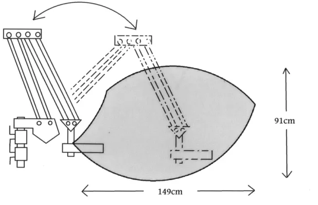
After testing I decided that in order for this system to be practical it must have a larger range of motion. With that in mind the original double arm idea was brought back but this time with gas springs instead of a restricted motion slider. The new system was designed to have a maximum horizontal reach 149cm and with a maximum vertical range of 94cm. The effective range of the system is shown in the following Figure 5. Additionally, unlike the slider design, this design could be oriented in the vertical direction as well as the horizontal. The new system needed to be moveable but once the user released the table the system had to maintain its position. The arms would be counterbalanced so that they would directly counter the effect of gravity on at the end effector or table.
000
0 0 01 91CM
149cm
The system was designed with aluminum arms, steel shoulder screws and delrin bushings in order to achieve a higher level of precision in the parallel linkages. Both ends of the system were made from metal tubing, one tube mounted to the wall and the other attached to the table. Using standard sized tubing would make it very easy to mount the machine and would allow the option to easily change out the style of the table being supported. Gas springs had to be selected to counterbalance the force of gravity of the system. Therefore, very few changes could be made to the system once the springs were selected because changing the mass of the system would undermine the effect of the springs.
4.2 Force analysis and spring selection
In order for the system to function properly it was necessary to carefully select the springs that were used. Gas springs have several advantages over compression or extension springs. Gas springs provide a constant force over their entire stroke length. Gas springs also tend to have longer stroke lengths and gas springs can be rated for very high force without becoming excessively large. Gas springs are safe compared to steel springs because internal dissipation reduces their maximum speed to one that is relatively low. Lastly, a single gas spring system can have variable force ratings, the difference being the pressure of the gas contained in the gas spring. A particular gas spring series was selected for use for exactly this reason. The system can be adjusted to support different weights by changing the gas springs with different force ratings, and because the springs have the same dimensions they can be changed out easily.
elbow
0
0
A
B
shoulder 0 wrist
Figure 6. Double-arm model design with gas springs
The energy states of arms A and B are independent; 01 and 02 do not affect each other. For simplicity, virtual work theory was used to determine force rating required for the gas springs. The following figure shows the gas spring and parallel linkages at the elbow.
y
12
lb
le
82
Figure 7. Parallel linages and gas springs at the elbow
The length of gas spring B (ib) is given in Eq. (1).
The virtual displacement of the spring and the height of the system are given in Eq. (2) and Eq. (3) respectively where length (L) represents the length of arm B.
S5b L1l2sinO2 (2)
12+12 -21112cos0 2
Sy = Lsin02 (3)
In order for the system to be balanced the work done by gravity must equal the work done by the gas spring. Using Eq. (2) and Eq. (3) the necessary force of the gas spring (Fspring) is given in Eq. (4). In Eq. (4) arm B is modeled as a uniform bar with its center of mass located at its half-length.
Fspring = 9 wrist + msup port + marmB * (4)
The two virtual displacements are not equivalent so it is not possible to perfectly balance the system. The appropriate gas spring was selected for the system based on the angle and sweep
of the each arm. This was done manually by minimizing the virtual work experienced by the arm. Figure 8 shows an example of the graph used to determine gas spring B. The blue dotted line represents the virtual work of gas spring B, red represents gravity and the solid green line is the summation of the two or the "experienced" work. Arm A was selected to have a functional range from 40 to 130 with respect to 01 and arm B from -45 to 75 with respect to 02.
Virtual Work on Arm B with Respect to Angle 30 ,.--- Gas Spring 20 -- Gravity Experienced S10 -20 -30 -40 -20 0 20 40 60 Angle (degrees)
Figure. 8 Characterization of virtual work acting at the elbow
Spring forces of 150 lbs. and 100 lbs. were selected to balance the system while
supporting an additional 8 lbs. The system was designed to hold the additional 8lbs because the average laptop weighs about 6lbs. The forces required were generated using spring pairs. A 90 lb and 60 lb force spring pair was used to generate the 150 lb force and a 60 lb and 40 lb was used to generate the 100 lb force.
5: Prototype construction
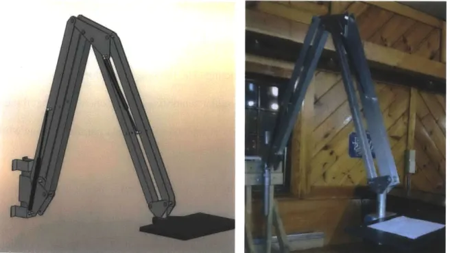
The prototype was designed to be simple, inexpensive and robust. The final CAD model of the design and the completed system are shown below in Figure 9. The system was designed to use the fewest unique parts. With the table unattached the arms weigh 17.6lbs. There are only
five unique fasteners in the system; shoulder screws which act as the axels, two types of bolts to attach the wrist and shoulder to the two axels, and 4-40 screws to affix the gas spring standoffs to the elbow and shoulder pieces. Excluding the table, which was designed to be interchangeable, the entire system is constructed from sixty-seven parts of which nineteen are unique. The system required sixty-six machining operations, though this does not include parts that were
pre-manufactured such as the collars and the gas springs. Of the machining operations nine were performed with a waterjet saw, six with band saw, two with lathe, twenty-four with drill, one by mill and twenty-two were tapping operations. Excluding the waterjet saw the remaining fifty-seven operations were reducible to nine unique operations.
The waterjet saw was used to great effect to construct the custom parts. The shoulder pieces, the elbow piece, the wrist pieces and the two of the gas spring standoffs were made in the waterjet saw from the same sheet of aluminum. The last two standoffs, the elbow standoffs, were made by cutting from a thicker piece of aluminum.
Figure 10. System elbow and parallel linkages
The standoffs were added to the shoulder and elbow pieces for three reasons. First, the added width improved the connection between the gas springs and the body of the system. The second reason was to shift the gas springs distally from the system so that during motion the gas springs would pass over the axels without interacting. The last reason was for reinforcement. The standoffs were attached by 4-40 screws. The shoulder standoff was positioned such that the gas spring acted on the shoulder 15cm below the axis of rotation of the upper parallel linkage while the elbow standoff was positioned 9cm below.
The parallel bar linkages were attached by 1/2" shoulder screws, the shoulder screws acting as axels so that the bars are free to rotate. The parallel linkages are all of equal length and with the center distance of the axels measuring 86cm. A hole was cut 34cm from the
was cut 45cm from the elbow-side axel of the elbow-wrist beam. The gas spring pairs were attached at these two holes using an aluminum rod that had been tapped for the gas springs ball joint fitting. The gas spring ball fittings compensated for misalignment problems.
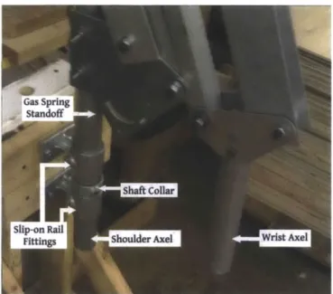
By nature of the parallel linkages the shoulder axel and wrist axel are always oriented in the same direction. The shoulder attached vertically to two slip-on rail fittings with a shaft collar in between the fittings which locks the axel in in vertical position. The shoulder axel is free to rotate. So long as the shoulder axel is oriented vertically then the table is always oriented parallel to the ground. The original mock-up was repurposed as a test stand so that the system could be tested without affixing it to a wall. The slip-on rail fittings were screwed into the face of the stand.
Fittngs Shoulder Axel Wris Axel
Figure 11. System elbow and shoulder attached to wall mount by slip-on fittings
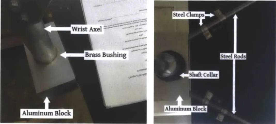
The table is plywood. In order to attach the table to the wrist axel an aluminum block was cut using a milling operation to create a hole for a brass bushing. The wrist axel then slids into brass bushing, the aluminum block is restricted vertically by a shaft collar but is still able to rotate. The aluminum block had two holes cut in the front face. Two steel rods are slid into the
holes, the rods lie 60 splayed open. Steel one-hole clamps were placed over the rod pair and then fixed to the table using screws. Once the clamps were in place the rods could no longer be removed. Using this system a new table can be added to the arm by simply removing the screws, placing the new table, and reattaching the screws.
rstAxel
BasBushing s
Aluminum Block
Figure 12. The table and aluminum attachment viewed from above (left) and below (right)
The entire system can be installed and uninstalled quickly and simply. The slip-on rail fittings are screwed into a wall or attached to a moveable base. The arm, table unattached, is slid into the slip-on rail fittings and the shaft collar is locked down using a set screw. The gas springs are restricted by using a strap clamp to prevent the arms from opening during installation. The table fitting is slid onto the wrist axel; the second shaft collar is under the table then tightened using a set screw. Finally, the strap clamp is removed and the system is available for use.
6: Prototype Feedback
Users were asked to test the final prototype and comment on the appearance and the ergonomics. Users were then asked what would have to be changed before they would consider purchasing the system. Most people stated that the system looked "industrial" and mentioned that
the system would look out of place in a residential setting. They said that the exposed aluminum, moving parts and the overall size of the system made them feel that the system belonged in a machine shop or factory. Users described the appearance as "mechanical" and "utilitarian". Several users also mentioned that the table looked independent of the rest of the system, that the table was small compared to the rest of the system. Some users claimed that the system might
scare young children.
Ergonomically, people mentioned that when changing the vertical position of the table it felt "smooth" and many were surprised by how far the system could reach. They also stated that turning the system and turning the table took more effort than changing the vertical position. Users were pleased to see that the table was always oriented parallel to the ground but that having the option to adjust the angle would also be useful. Also, without a shell there are several pinch-points between the parallel linkages.
Before users would consider buying the system for home use they would need the entire system to be covered with a smooth shell. The shell would eliminate pinch points and give the system a uniform appearance. The system would also have to be thinner in both width and depth. They mentioned that the system had greater reach than necessary and that the length of the arms could be shortened if the entire system was made thinner. Lastly, users stated that if the design was put into use it should be adjustable for weight and that it should also include a method for locking position.
7: Conclusions and Future Work
The research presented details the ideation, development and construction of a gravity balanced table. The research fulfilled the goal of using design process to create a functioning alpha prototype from a general idea. The table could be oriented in vertical and horizontal directions and could also be turned about the pivoting base. Once the user released the table, the system would maintain its position until the user decided to move it again. The prototype
fulfilled all the design requirements. The arm was able to support the weight of the working surface, it could be moved while holding contents and the system did not require a power source. The design process was demonstrated effectively using ideation, mock-up, dynamic analysis, and design techniques. Effective machining techniques were demonstrated including operations using mill, lathe, drill, and waterjet.
If this project were to continue I would prepare a methodology for the design of a
counterbalancing system for several applications. The balancing technique used can be applied to a variety of situations. Suggested alternative designs include a moving workstation for painters, traveling toolbox for mechanics, large-scale mobile platform to replace the necessity of
scaffolding. The technique could be applied to robotic arms to simplify their dynamics be reducing or eliminating the effect of gravity. The low cost of gas springs, the large possible stroke lengths and the ease of installation of a gas spring make them exceptionally useful as a means of counterbalancing the effects of gravity.
The alpha prototype design demonstrates functionally sound techniques for designing structures counterbalanced against gravity. While the system currently has ergonomic
considerations that need to be addressed before it can be marketed, I am confident that the counterbalancing techniques demonstrated can be replicated effectively for a variety of purposes.
References
Ulrich, Karl T., and Seven D. Eppinger. Product Design and Development. 5th. New York: McGraw-Hill, 2012. Print.
T. R. Kane and D. A. Levinson, Dynamics: theory and applications, McGraw-Hill, New York, 1985 Shigley, Joseph E., and Charles R. Mischke. Mechanical Engineering Design. 5th. New York: McGraw-Hill, 2002. Print.