Delamination in Reinforced Concrete Retrofitted with
Fiber Reinforced Plastics
by
Brian Phillip Hearing
Submitted to the Department of Civil and Environmental Engineering
in partial fulfillment of the requirements for the degree of
Doctor of Philosophy in Civil Engineering
at the
MASSACHUSETTS INSTITUTE OF TECHNOLOGY
February 2000
©
Massachusetts Institute of Technology 2000. All rights reserved.
Author ...
Department of
Certified by ...
Accepted by...
Civil and Envir6 mental Engineering
January
7,
2000
... . ...
Oral Buyukozturk
Professor of Civil and Environmental Engineering Thesis SupervisorK0"
Daniele Veneziano
Chairman, Department Committee on Graduate Students
MASSACHUSETTS INSTITUTE OF TECHNOLOGY
Delamination in Reinforced Concrete Retrofitted with Fiber
Reinforced Plastics
by
Brian Phillip Hearing
Submitted to the Department of Civil and Environmental Engineering on January 7, 2000, in partial fulfillment of the
requirements for the degree of Doctor of Philosophy in Civil Engineering
Abstract
The addition of fiber-reinforced plastic (FRP) laminates bonded to the tension face of con-crete members is becoming an attractive solution to the rehabilitation and retrofit of damaged structural systems. Flexural strength is enhanced with this method but the failure behavior of the system can become more brittle, often involving delamination of the composite. This study investigates failure modes including delamination with the use of fiber reinforced plas-tics to rehabilitate various concrete structures. The focus is on delamination and its causes, specifically in the presence of existing cracks in the retrofitted concrete system. First, de-lamination processes in FRP retrofitted concrete sytems are studied through combined ex-perimental and analytical procedures. The delamination process is observed to initiate in the concrete substrate with microcracks that coalesce into an unstable macrocrack at failure. This macroscopic behavior is modeled through a finite element procedure with a smeared crack approach, which is found to be limited in the ability to represent the stress intensity at the delamination tip. For this reason it is shown that interfacial fracture mechanics can be used to describe the bimaterial elasticity and complex stress intensity at the delamination tip and provide a criterion governing the propagation of delamination using energy methods. Then, peeling processes occurring at existing cracks in the retrofitted system are studied through fracture mechanics based experimental and analytical procedures. An experimental program involving specialized shear notch specimens demonstrates that the location of the notch and laminate development length are influential on the shear crack peeling process.
A finite element procedure is used to evaluate the crack driving forces applied at the shear
notch crack mouth, and the fracture analysis is extended to evaluate initiation of peeling at the shear notch scenario. Finally, delamination failures in FRP retrofitted reinforced concrete beams representing "real-life" retrofit scenarios are investigated. An experimen-tal and analytical program is conducted to investigate influences on the failure processes. The application of the fracture based peeling analysis to a quantitative design procedure is investigated, and a computational design aid to assist the iterative design procedure is
developed.
Thesis Supervisor: Oral Buyukozturk
Acknowledgments
I would first like to express my deepest gratitude to my thesis supervisor Professor Oral
Buyukozturk. In addition to his support and friendship over the past six years, he has pro-vided the unwavering source of inspiration, determination, and leadership that is so essential for the successful execution of a project of this scale. I am equally thankful for the benev-olence and guidance of Professor Urs Meier of the Swiss Federal Laboratories for Materials Testing and Research (EMPA), for providing the opportunity for my three month visit to EMPA; the knowledge we gained through this collaboration has helped launch our group at MIT into the forefront of this field.
I am honored to have Professor Frederick McGarry in the Department of Materials Science
in my thesis committee as well as Professor Christopher Leung of the Hong Kong University of Science and Technology. I am thankful for the valuable comments and encouragement from them as well as the help and collaboration provided by Professor Franz Ulm. Addi-tionally, I would like to thank Professor Ferdinand Rostasy from the Technical University of Braunschweig for his collaboration with our work and research group. Gratitude is also extended to Professor M. Forde from the University of Edinburgh, Professor B. Hillemeier from Technische Universitat Berlin (TUB), and Dr. H. Wiggenhauser from Bundesanstalt fur Materialforschung (BAM).
I am grateful to Dr. Ken Chong of the National Science Foundation, who was the
cog-nizant official of this program. Additional support was gratefully received from the Sika Cor-poration and the Swiss Federal Laboratories for Materials Testing and Research (EMPA). Thanks are also extended to Arthur and Steve Rudolph for their help in the laboratories at MIT.
I would like to thank all my friends and officemates for their encouragement and friendship
through my time at MIT, in particluar: Jonathan Berry, Dr. Stephen J. Ludwick, J. Nicholas Laneman III, Oguz Gunes, Erdem Karaca, Dave Cuneo, and many others. Also, I have enjoyed working with Ricardo DeRojas in the UROP program for the last three years.
I will always have special gratitude and love for my parents, Dr. Vincent and Elizabeth
Hearing, who have provided the most ideal and nurturing environment for my life and stud-ies, including over 500 Sunday morning phone calls. I will always appreciate the love of my sister, Dr. Laura Koniver, and my brother, David Hearing.
I would finally like to thank the love of my life and special pal, my beautiful wife Marina
for her love, endless support, and lasagna. Without her sacrifice and devotion I never would have survived this work.
Contents
1 Introduction
1.1 Retrofit of Concrete Structures . . . .
1.1.1 Use of FRP to Retrofit Concrete Structures . . . . 1.1.2 Application of FRP Materials for Retrofit of Reinforced Concrete . . 1.1.3 Principles of the Retrofit Technique . . . . 1.2 History and Development of Reinforced Concrete Retrofit with FRP Materials
1.3 Research Objectives . . . . 1.4 Research Approach . . . .
1.5 O utline of Thesis . . . .
2 Use of Fiber Reinforced Plastics to Retrofit Reinforced Concrete
2.1 FRP Retrofitting Materials . . . . 2.1.1 Fiber Reinforced Plastic Laminates . . . . 2.1.2 A dhesives . . . .
2.1.3 Manufacturers . . . . 2.2 Mechanical Characteristics of FRP Composite Laminates
2.2.1 Elastic Modulus . . . . 2.2.2 Strength . . . .
2.2.3 Energy Absorption . . . . 2.2.4 Fatigue Resistance . . . .
2.3 Retrofit of Concrete Structures . . . . 2.3.1 B ridges . . . .
2.3.2 Columns and Seismic Retrofit . . . .
21 21 22 22 23 24 26 26 27 30 . . . . 30 . . . . 30 . . . . 35 . . . . 37 . . . . 39 . . . . 39 . . . . 40 . . . . 41 . . . . 42 . . . . 43 . . . . 43 . . . . 46
2.3.3 Buildings . . . .
2.3.4 W alls . . . . 2.4 Sum m ary . . . .
3 Mechanics of FRP Retrofitted Reinforced Concrete 3.1 Failure Mechanisms ...
3.1.1 Flexural Failures . . . .
3.1.2 Shear Failures . . . .
3.1.3 Debonding . . . .
3.2 Servicability of FRP Laminated Concrete
3.2.1 Ductility . . . .
3.2.2 Stiffness . . . .
3.3 Cyclic and Environmental Behavior . . .
3.4 Summary . . . .
Beams
Beams
4 Experimental Program: Preliminary Investigation 4.1 Delamination Notch Specimens . . . . 4.1.1 Testing Specimen . . . . 4.1.2 M aterials . . . .
4.1.3 Scope of Tests . . . . 4.1.4 Experimental Results . . . . 4.2 Shear Notch Specimen . . . . 4.2.1 Experimental Procedure . . . . 4.2.2 Experimental Results . . . . 4.3 Experimental Plan . . . . 4.4 Summary . . . .
5 Experimental Program: Local Delamination 5.1 Introduction . . . .
5.2 Specialized Delamination Specimen...
Fracture Investigation 5.3 M aterials ... . . . . 48 . . . . 48 . . . . 50 51 51 53 58 59 74 74 76 77 78 79 79 80 82 82 82 83 85 85 86 88 91 91 91 93
5.3.1 Concrete . . . . 5.3.2 Reinforcing Steel . . . . 5.3.3 FRP Laminate . . . . 5.3.4 Adhesive . . . . 5.3.5 Laminate/Epoxy Interface 5.3.6 Epoxy/Concrete Interface 5.4 Test Procedure . . . . 5.4.1 Strain Gauges . . . . 5.4.2 Silverpainting . . . . 5.4.3 Magnifying Camera . . . . 5.4.4 Ultrasonic Testing . . . . 5.5 Experimental Results . . . . 5.5.1 Silverpainting . . . . 5.5.2 Strain Gauges . . . . 5.5.3 Effect of Adhesive . . . . 5.5.4 Effect of Bonded Laminate Leng
5.6 Summary of Experimental Results . . .
6 Analytical Procedure
6.1 Introduction . . . .
6.2 Analytical Program . . . .
6.3 Delamination Fracture Process . . .
6.3.1 Thermodynamics of Fracture
6.3.2 Finite Element Simulations
6.3.3 Summary and Limitations of 6.4 Interfacial Fracture Mechanics . . .
6.4.1 Introduction . . . .
6.4.2 Bimaterial Elasticity . . . .
6.4.3 Crack Tip Fields . . . . 6.4.4 Crack Propagation . . . . . . . . . 9 3 . . . . 9 4 . . . . 9 4 . . . . 9 4 . . . . 9 5 . . . . 9 7 . . . . 9 7 . . . . 9 8 . . . . 9 8 . . . . 9 8 . . . . 9 8 . . . . 9 9 . . . . 1 0 1 . . . . 1 0 1 . . . . 1 0 2 th . . . . 102 105 106 106 106 108 108 110 125 126 126 128 129 130 . . . . . . . . . . . . . . . . . . . .
Finite Element Simulations
. . . . . . . . . . . . . . . . . . . .
6.4.5 Crack Path Evaluation . . . .
6.5 Linear Elastic Fracture Model . . . . 6.5.1 Delamination Criteria . . . .
6.5.2 Resistance to Delamination . . . . .
6.5.3 Dimensional Analysis . . . .
6.5.4 Comparison to Experimental Results
6.6 Sum m ary . . . .
7 Delamination From Shear Cracks
7.1 Shear Crack Peeling . . . . 7.2 Peeling Models . . . . 7.3 Experimental Program . . . . 7.3.1 Test Procedure . . . .
7.3.2 Experimental Results . . . .
7.3.3 Effect of Notch Location . . . . 7.3.4 Effect of Development Length . . . .
7.4 Analytical Procedure . . . . 7.4.1 Stress Field . . . . 7.4.2 Crack Path Prediction . . . . 7.4.3 Peeling Model and Criteria . . . .
7.5 Sum m ary . . . .
8 Delamination in Beams Representing 8.1 Real-World Retrofit Scenarios . . . . 8.2 Experimental Program . . . .
8.2.1 Test Procedure . . . .
8.2.2 Test Results . . . .
8.2.3 Effect of Shear Capacity . . .
Real-World . 133 136 138 140 143 146 148 149 149 153 156 157 158 161 164 165 165 168 171 179 181 182 185 185 186 189 191 191 192 Applications
8.2.4 Effect of Laminate Length . . . . .
8.2.5 Summary of Experimental Program
8.3.1 Failure Mechanism Investigation . . . .
8.3.2 Effect of Shear Capacity and Stirrup Spacing.
8.3.3 Effect of Laminate Thickness . . . .
8.3.4 Linear Elastic Fracture Model . . . . 8.4 Sum m ary . . . .
9 Designing for Delamination
9.1 Existing Design Procedures . . . . 9.1.1 Professional Organizations . . . .
9.1.2 Retrofit System Manufacturer . . . .
9.1.3 Independent Researchers . . . .
9.2 Delamination Design Criteria . . . . 9.2.1 Goals and Design Philosophy . . . . 9.2.2 "Yielding before Delamination" Criteria . . . 9.2.3 Generalized Beam Loading . . . .
9.3 Size Effect in Delamination . . . .
9.4 Design Procedure . . . . 9.4.1 Phase 1: Materials Selection . . . . 9.4.2 Phase 2: Flexural Design . . . .
9.4.3 Phase 3: Evaluation of Shear Capacity . . . .
9.4.4 Phase 4: Detailing for Peeling . . . . 9.4.5 Phase 5: Anchorage Design . . . .
9.5 Computational Design Aid . . . .
9.5.1 Worked Example 1: Laboratory Specimen . .
9.5.2 Worked Example 2a: Simply Supported Beam
9.5.3 Worked Example 2b: Beam Repair Situation . 9.5.4 Worked Example 3: Slab . . . .
9.6 Sum m ary . . . . 193 193 195 197 202 204 205 . . . . 205 . . . 207 . . . 208 . . . 210 . . . 210 . . . 210 . . . 213 . . . 217 . . . . 220 . . . 222 . . . . 224 . . . . 227 . . . . 228 . . . . 229 . . . . 231 . . . . 233 . . . . 237 . . . . 239 . . . . 241 . . . . 242
10 Summary, Conclusions, and Future Work
10.1 Summary and Results . . . .
245 245
10.2 C onclusions . . . . 252 10.3 Future Work . . . . 257
A Iterative Fracture Analysis Script 270
List of Figures
1-1 Preparation of materials for lamination . . . . 23
1-2 Curing and finish of laminated system . . . . 24
1-3 Internal forces and strain compatibility of beam strengthened in flexure with
FR P lam inate . . . . 25
1-4 Evolutionary research approach . . . . 27
2-1 SEM micrographs of common reinforcing fibers, after (Hull and Clyne, 1996) 31
2-2 Fiber types based on orientation, after (Hull and Clyne, 1996) . . . . 33 2-3 Carbon fiber prices and volume produced over last two decades . . . . 36
2-4 Stress-strain diagram for three epoxy materials, after (Schwartz, 1996) . . . 38 2-5 Laminate stiffness as a function of loading direction and fiber volume fraction 41
2-6 S-N curves of fatigue performance of unidirectional FRP composites, after
(Hull and Clyne, 1996) . . . . 42
2-7 Repair of roadway bridge with damaged prestressing tendon (Meier, 1992) 44
2-8 Bridge retrofit to reduce steel tendon stresses (Rostasy et al. 1992) ... 44
2-9 Roadway bridge strengthened with GFRP (Nanni, 1995) . . . . 45 2-10 Repair of prestressed box beam bridge girders using tow sheets (Finch et. al.
1994)... ... 45 2-11 FRP Retrofit wrapping of columns (Neale and Labossiere, 1998) . . . . 47
2-12 Automated column wrapping system (TYFO, 1998) . . . . 47
2-13 Use of FRP to retrofit building slab and beam members (Neale and Labossiere, 1998)... ... 48 2-14 FRP retrofit of walls (Structural Preservation Systems, 1998) . . . . 49
3-1 Failure modes in FRP retrofitted concrete beams . . . . 52
3-2 Flexural failures . . . . 53
3-3 Performance of retrofitted concrete beams . . . . 55
3-4 Influence of the FRP and steel reinforcement on the flexural failure mechanism (after Plevris, 1991) . . . . 57
3-5 Shear failure (Vichit-Vadakan, 1997) . . . . 58
3-6 FRP shear reinforcement configurations, after (Khalifa et al., 1998) . . . . . 60
3-7 Debonding mechanisms of retrofit beams (Vichit-Vadakan, 1997) . . . . 61
3-8 Peeling in actual structures, after (Karbhari, 1997) . . . . 61
3-9 Local stress intensities and microcrack initiation scenarios . . . . 63
3-10 Damage model of bond stress-slip failure, after (Hankers, 1995) . . . . 63
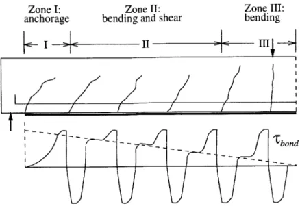
3-11 Bonding zones and antimetric bond stress peaks in retrofitted flexural mem-bers (After Neubauer and Rostasy, 1997) . . . . 64
3-12 Zone I: Anchorage of plate end (after Neubauer and Rostasy, 1997) . . . . . 65
3-13 High speed video clips of plate end zone failures, after (Hankers, 1995) . . . 65
3-14 Elastic scenario and stress distribution, after (Malek et al., 1997; Taljsten 1997) 67 3-15 Ultimate (anchorage) bond force T for steel- and CFRP-plates (after Hankers, 1997) ... ... .. ... 69
3-16 Investigation techniques of bond integrity through lap-shear models, after (Chajes et al., 1996) . . . . 70
3-17 Zone II: Shear force and moderate bending moments (after Neubauer and R ostasy, 1997) . . . . 71
3-18 Fracturing process from an initially notched laminated concrete specimen (af-ter W u et al., 1997) . . . . 71
3-19 Investigation techniques of bond integrity through peeling tests, after (Karb-hari et al., 1997) . . . . 73
3-20 Zone III: High bending moments, low shear forces (after Neubauer and Ros-tasy, 1997) . . . . 74
3-21 Curvature ductility ratio for flexural failures as a function of CFRP
4-1 2 meter and 3 meter specimen dimensions and test setup (in mm)
4-2 Instrumentation applied to the 3 meter beam . . . . 81
4-3 Load versus midspan deflection for the 3 meter specimen . . . . 83
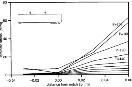
4-4 Stresses in the tested 3m beam near the delamination notch tip . . . . 84
4-5 Load versus midspan deflection for 2 meter specimens . . . . 84
4-6 Instrumentation applied to the 3 meter shear notch beam . . . . 85
4-7 Load versus midspan deflection for 3 meter specimen . . . . 86
4-8 Stresses in the laminate near the crack tip . . . . 87
4-9 Crack mouth opening displacements . . . . 87
4-10 Three phase experimental plan . . . . 89
5-1 Specialized delamination test specimen . . . . 93
5-2 Laminate/epoxy interface testing specimens . . . . 95
5-3 Fracture tests on the concrete adhesive interface . . . . 97
5-4 Use of ultrasonic NDT to detect delamination in FRP retrofitted concrete beams 99 5-5 Results of ultrasonic nondestructive testing on FRP laminated concrete beams 100 5-6 Midspan deflection and cracking patterns for experimental program . . . 100
5-7 Oscilloscope output results from silverpainting . . . 102
5-8 Results from the strain gauges on the beam with 1.4m bonded length . . . 103
5-9 Delamination process zone development . . . 103
5-10 Sample delaminated FRP with thin layer of concrete substrate . . . 104
5-11 Images of process zone development obtained with magnifying camera . . . . 104
6-1 Visual representation of analytical plan and tools for investigating the delam-ination process . . . 107
6-2 Relationship between material energy release rate and stress-crack opening displacem ent . . . 110
6-3 Material models used in FE analysis . . . 114
6-4 Finite element mesh and closeup of initial notch used in the smeared crack analysis . . . . 116
6-5 Investigation of mesh objectivity . . . . 117
6-6 Investigation of influence of mesh size . . . . 118
6-7 Delamination band to simulate peeling failures . . . . 119
6-8 Comparison of finite element load/displacement results with laboratory results 120 6-9 Comparison of finite element cracking patterns with laboratory results . . . . 121
6-10 Progressive crack advance from the initial delamination notch for laminate length 1 = 900 mm (beam span L = 1800 mm) . . . . 123
6-11 Stresses in the laminate under increasing loads . . . . 124
6-12 Visualization of the functions of interfacial fracture mechanics . . . . 127
6-13 Conventions at crack tip and geometry of kinked crack . . . . 128
6-14 Refined finite element model of delamination specimen . . . . 130
6-15 Three point bending mesh used to validate the virtual crack extension method 132 6-16 Results of finite element crack deflection study . . . . 134
6-17 Comparison between normalized deflection ratios and semi-infinite theoretical results . . . . 136
6-18 Idealization of fracture process through linear elastic fracture model . . . . . 137
6-19 Equivalent strain and complementary strain energy in a linear elastic system 140 6-20 Idealization of laboratory specimen into discrete cross sections . . . . 141
6-21 Idealization of energy released during fracture process . . . . 142
6-22 Delamination loads predicted analytically with experimental results . . . . . 147
7-1 Differential crack mouth opening displacements causing peeling, after (Neubauer and Rostasy, 1999) . . . . 150
7-2 Peeling process from shear cracks, after (Kaiser, 1989) . . . . 152
7-3 Components of shear resistance to peeling, after (Kaiser, 1989) . . . . 155
7-4 Initial shear notch delamination test specimen . . . . 157
7-5 Initial shear notch cut with a thin diamond saw blade . . . . 158
7-6 Load/midspan deflection curves for initial shear notch specimens . . . . 160
7-7 Sample strain gauge results for beam (c = 300 mm, 1 = 75 mm) at various load levels ... ... 161
7-9 Images of process zone development obtained with magnifying camera . . . . 162
7-10 Results from silverpaint on the shear notched specimen . . . . 163
7-11 Representation of the analytical plan for evaluation of peeling mechanisms at shear notches ... ... 166
7-12 Finite element mesh used to study the shear notched delamination beams . . 167
7-13 Interfacial shear stresses from shear notches at different locations . . . . 168
7-14 Refined finite element mesh used in the fracture analysis . . . . 169
7-15 Possible deflection scenarios for an existing crack in the concrete member . . 170
7-16 Finite element mesh and midspan deflection curve . . . . 172
7-17 Progressive delamination rupture from initial shear notch (showing only rup-tured elements) for simulations c = 150 mm, ld = 225 mm . . . . 173
7-18 Laminate stresses near the shear notch for the notched specimen (c = 300 mm, I = 75 m m ) . . . . 174
7-19 Idealization of fracture process in the shear notch specimen . . . . 175
7-20 Idealization of energy released during the peeling process . . . . 176
7-21 Idealization of laboratory specimen into discrete cross sections . . . . 178
7-22 Delamination loads predicted analytically, shown with experimental results . 179 8-1 Crack widths in precracked FRP retrofitted concrete beams, after (Meier and K aiser, 1991) . . . 183
8-2 Failure modes in precracked FRP strengthened concrete beams, after (Arduini et al., 1997) . . . . 184
8-3 Real-life precracked test specimen . . . . 186
8-4 Preloading crack patterns and delamination process, for beam s = 150, 1 = 1200187 8-5 Load/midspan deflection curves for precracked specimens . . . . 188
8-6 Results from strain gauges, for beam s = 150, 1 = 1500 . . . . 190
8-7 Representation of the analytical plan for evaluation of delamination in pre-cracked specim ens . . . . 192
8-8 Finite element mesh and cracking patterns before and after laminate element birth . . . . 194
8-9 Load/deflection curves for precracked finite element simulation . . . . 195
8-10 Rupture of concrete elements during the delamination process at various load levels... ... 196
8-11 Idealization of stages of delamination initiation and ultimate propagation . . 198
8-12 Idealization of energy release at initation and ultimate delamination . . . . . 199
8-13 Idealization of precracked specimen into discrete cross sections . . . . 201
8-14 Delamination loads predicted analytically, shown with experimental results . 202 9-1 Use of externally bonded steel plate stirrups, from (Deutches Insitut fur Bautechnik, 1998) . . . 206
9-2 Equivalent shear capacity representing peeling resistance . . . 208
9-3 Illustration of steel yielding before delamination criteria . . . 211
9-4 Nomenclature of an idealized retrofitted cross section . . . 213
9-5 Contourplots of Equation 9.8 with p, and p, for three common fiber stiffnesses 214 9-6 Retrofitted system loading history with linear service behavior . . . 215
9-7 Distributed beam loading scenario . . . 215
9-8 Size effects, from (Bazant and Planas, 1998) . . . 218
9-9 Size effect in FRP retrofitted reinforced concrete structures . . . 221
9-10 Flowchart of design process . . . 223
9-11 Internal forces and strain compatibility of beam strengthened in flexure with FRP lam inate . . . 226
9-12 Plate anchorage scenario, after (Rostasy and Neubauer, 1998) . . . 229
9-13 Calculation of anchorage length, from (Deutches Insitut fur Bautechnik, 1998) 232 9-14 Computational design tool, at http: //infra. mit .edu/Design/Design2. html 234 9-15 Beam scenario used in Design Example 1 . . . 235
9-16 Dimensions of finalized Example 1 . . . 237
9-17 Specifications of strengthened beam (Example 2), after (Saadatmanesh and M alek, 91) . . . 238
9-18 Dimensions of finalized Example 2b . . . 241 9-19 One-way slab design example, (Example 3), after (Nilson and Winter, 91) . 242
9-20 One-way slab design example (Example 3) . . . .2 10-1 Idealization of delamination process zone development . . . 247
10-2 Delamination loads of the delamination specimens predicted analytically com-pared to experimental results . . . 248 10-3 Idealization of softening zone development at shear notches . . . 249
10-4 Delamination loads of shear notched specimens predicted analytically, shown with experimental results . . . 250
10-5 Delamination loads of precracked real-life specimens predicted analytically,
shown with experimental results . . . 251
10-6 Contourplots of maximum allowable thickness for existing steel ratios retrofitted
with carbon fiber laminates . . . 253 243
List of Tables
2.1 Properties of commercial composite reinforcing fibers, after (ACI440R) . . . 32
2.2 Selected properties for different types of resins, from (Hull and Clyne, 1996) 34 2.3 Typical mechanical properties of unidirectional laminates, from (Schwartz, 1997)... ... 40
4.1 Properties of materials used in the preliminary experimental program . . . . 82
5.1 Properties of materials used in the experimental program . . . . 94
5.2 Results of ASTM-D5868 Lap Shear Adhesion testing . . . . 96
5.3 Results of modified ASTM-D1876 Peel Resistance testing . . . . 96
5.4 Results of the experimental program . . . . 101
6.1 Results from investigation into influences on the finite element model . . . . 122
6.2 Nonconvergence results from the finite element investigation . . . . 125
6.3 Properties of bimaterial interfaces used in the experimental program . . . . . 129
6.4 Results of three point bending virtual crack extension verification . . . . 132
6.5 Results of finite element energy release rate investigation . . . . 135
7.1 Results of initial shear notch specimens . . . . 159
7.2 Maximum deflected and interfacial energy release rates . . . . 168
7.3 Results of smeared crack finite element procedure . . . . 173
8.1 Results of initial shear notch specimens . . . . 187
8.2 Maximum loads (in kN) of precracked finite element simulations invetigating influence of shear capacity ... ... 197
8.3 Maximum loads of precracked finite element simulations invetigating influence
of laminate thickness . . . . . . . - - - 197
9.1 Size effect analysis of experimental data . . . 220
9.2 Properties of materials used in Design Example 1 . . . 235 9.3 Materials used in design Example 2, after (Saadatmanesh and Malek, 98) . . 238
9.4 Materials used in design Example 3, after (Nilson and Winter, 91) . . . 243
List of Symbols
a = normalized unbonded length, a/l
#
= normalized shear span length, 1/L= d/h E = strain rq = mismatch parameter A = upgrade ratiop77i/prs y= shear modulus y = Poisson's ratio p = reinforcement ratio - = stress T = shear stress
p= bulk dissipation energy
= phase angle
w = physical crack deflection angle
F = fracture energy
<D= internal strain energy
Q = volume of a body
a = unlaminated length of beam
b = width
c = crack location
d = depth to flexural steel
h = height of section
1 = shear span
s = stirrup spacing
U = horizontal crack opening displacement v = vertical crack opening displacement
D = total energy dissipation
E = modulus
M moment
Chapter 1
Introduction
1.1
Retrofit of Concrete Structures
Infrastructure repair and rehabilitation represents a significant challenge facing the concrete industry. Repair of concrete deterioration accounts for a large portion of structural rehabil-itation needs; for example, over 84,000 bridges in the European Union (Nicklisch, 1999) and 42% of all highway bridges in the United States (Cooper, 1991) are considered structurally deficient. Rehabilitation project costs can range from $500,000 for a smaller bridge to over
$500,000,000 for larger projects such as the East River Crossing in New York (New York City
Department of Transporation, 1991). Upgrading structural load capacity is also a substantial part of the rehabilitation market; the railway industry has estimated an annual structural maintenance cost increase from $200M to $500M due to upgrading maximum allowable car loads from 286,000 pounds to 315,000 pounds (Sharma et al., 1994). Remediation of design and construction errors, estimated at 80% of all structural repairs (Jungwirth, 1995), had reached project sizes of over $5,000,000 by 1997 (Thomas, 1998), and seismic retrofit of columns and joints in earthquake-prone regions is now becoming mainstream. As a com-bined result of these many structural rehabilitation needs, concrete repair and rehabilitation
has become the industry's growth sector.
In response to the growing need for concrete repair and rehabilitation a large number of techniques for structural strengthening have been developed. A 1987 study identified eight popular techniques for strengthening bridges (Klaiber et al., 1987), ranging from external
prestressing to additional supports to the bonding of external materials. Strengthening through attachment of external materials has become popular because it is often the most economical choice. The technique involves the attachment of additional strengthening ma-terials to the tensile surface of the concrete element, thereby strengthening it through the addition of another tensile tendon. First uses of this method with concrete infrastructure were reported in 1967 with the addition of steel plates to increase the capacity of flexural members (Fleming and King, 1967; Lerchenthal, 1967). This technique became popular in Europe over the next decade until the early 1980s when fiber reinforced plastic (FRP) mate-rials were introduced as an attractive substitute for steel (McKenna and Erki, 1994). Since then, fiber reinforced composite materials have experienced rapid growth in replacing steel
as the choice of materials for retrofitting concrete structures (Karbhari et al., 1997).
1.1.1
Use of FRP to Retrofit Concrete Structures
Advances in the fields of plastics and composites have resulted in the development of high-strength fiber-reinforced plastics that offer great potential for cost-effective retrofitting of concrete structures. These materials exploit the advantages of high tensile strength fibers and are characterized by excellent corrosion resistance, fatigue resistance, low densities, and high specific stiffness and strengths (Meier, 1992). Fiber reinforced plastics have been used to retrofit concrete members such as columns, slabs, beams, and girders in structures including bridges, parking decks, smoke stacks, and buildings. Recently, the use of FRP bonded to
deteriorated, deficient, and damaged reinforced concrete structures has gained popularity in Europe, Japan, and North America.
1.1.2
Application of FRP Materials for Retrofit of Reinforced
Concrete
Primary benefits of FRP materials for reinforced concrete retrofit include the ease of ap-plication and the flexibility of the apap-plication procedure. The apap-plication procedure can be categorized into several distinct steps. First, prior to strengthening the integrity, condi-tion, and history of the structure must be evaluated. Any special damage, deterioracondi-tion, or
(a) preparation of the concrete (b) application of adhesive to
surface laminate
Figure 1-1: Preparation of materials for lamination
structural conditions must be assessed for consideration of the retrofit design. Following this assessment, the optimal retrofit system and materials are selected and the retrofit section is designed. The bonding work starts with preparation of the concrete surface through me-chanical scaling to remove any weak, deteriorated, and cast-surface concrete, as illustrated in Figure 1-la. Any defects such as existing cracks can be remedied through techniques such as epoxy injection and primer is applied to the prepared concrete surface according to man-ufacturer's specifications if necessary. The retrofitting materials are prepared by thoroughly cleaning the FRP laminate and applying other conditions such as prestressing. Then, the adhesive is applied, either to the laminate with pre-impregnated systems (Figure 1-1b) or directly to the concrete with wet-layup systems. The FRP material is then secured to the structure, typically through bolting of supporting beams, scaffolding, or vacuum systems, as shown in Figure 1-2(a). Excess adhesive is removed and curing procedures are applied per manufacturer's recommendations. After curing and removal of the application materials (Figure 1-2b), additional finishing such as fireproofing can be applied.
1.1.3
Principles of the Retrofit Technique
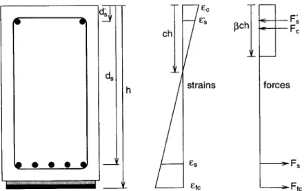
Flexural strengthening of concrete members through retrofit is accomplished primarily by increasing the moment capacity through an additional tension tendon. Strain compatibility is usually assumed in the elastic sections (ACI Committee 440F, 1998), as shown in Figure 1-3;
(a) laminate secured to concrete (b) securing removed and laminate
during cure with silverpainting
Figure 1-2: Curing and finish of laminated system
therefore, effective bonding is essential to assure composite action in the system. Theoretical increases in flexural capacity can be very large (Saadatmanesh and Ehsani, 1990b); however, limitations can be imposed by ductility requirements and other failure modes.
1.2
History and Development of Reinforced Concrete
Retrofit with FRP Materials
Retrofit of concrete structures by plating was first introduced using steel in 1967 (Fleming and King, 1967; Lerchenthal, 1967). Research into design of these systems concentrated on flexural behavior of large scale concrete beams (Irwin, 1975; MacDonald, 1978; Jones et al.,
1982). Design guidelines in the form of charts describing the retrofit ratio with respect to
existing internal ratio for various flexural failure modes were developed (Ladner, 1983). Other aspects that have been investigated include effects of plate thickness, adhesive thickness, and lap joint behavior (Swamy et al., 1989; Van Gemert, 1980). Long-term performance has also been investigated (Calder, 1979; Swamy et al., 1995). Recently, work on issues related to bonding and plate separation of steel retrofit systems has been conducted (Oehlers, 1992; Roberts, 1989; Jansze, 1997).
Early work in the use of composite materials for structural applications involved fiber-glass and concrete (Rubinsky and Rubinsky, 1954). Experimental work incorporating these
chl ~ pchl F
ds-h strains forces
@ 0 -Es Fs
Efc Ffc
Figure 1-3: Internal forces and strain compatibility of beam strengthened in flexure with FRP laminate
materials in the retrofit of concrete structures has been reported as early as 1978 in Ger-many (Wolff and Miessler, 1989). Since 1982, the use of carbon-fiber based FRP materials has been pioneered in Switzerland at EMPA (Kaiser, 1989); carbon has since become the material of choice in retrofitting (Meier, 1992). Benefits of carbon FRP over steel plates for retrofit include corrosion resistance, weight savings, project cost savings, fatigue behavior, flexible forming, and lack of length restrictions.
Research into the flexural behavior of FRP retrofitted systems demonstrated both the applicability of strain compatibility analysis as well as the significant potential of this tech-nique (Saadatmanesh and Ehsani, 1990b; Meier et al., 1992; Deuring, 1993; Inoue et al., 1996). Additionally, research into the use of FRP systems for increasing shear capacities has also been conducted (Berset, 1992; Sharif et al., 1994; Chajes et al., 1995b). However, new failure modes including plate separation, anchorage failures, and shear collapse were shown to limit the potential gains (Buyukozturk and Hearing, 1998). Many of these failure modes involved brittle delamination of the retrofitted material from the concrete substrate; due to the lack of ducility in these failure modes, researchers have called for better understanding of
delamination mechanisms (Saadatmanesh and Ehsani, 1990b; An et al., 1991; Meier, 1992; Chajes et al., 1994).
delam-ination failures (Ritchie et al., 1991). Different delamdelam-ination failures exist including peeling from existing concrete cracks, anchorage failures, and failure of the concrete between the lam-inate and the flexural steel. These complex failure mechanisms have been studied (Kaiser,
1989; Arduini et al., 1997; Hankers, 1997) but effective simplified techniques for analysis
and evaluation of retrofit system designs are not widely available. Additionally, very limited experimental and prototype experience is available. Furthermore, information on the distin-guishing characteristics of and interaction between the various debonding failure modes is available. It has been concluded that that failure criteria for laminated systems need to be established (Triantafillou et al., 1992; Meier, 1992); thus, the influence of these failure modes on the performance and integrity of laminated concrete systems must be evaluated before confident application of FRP laminates for strengthening of concrete structures is possible.
1.3
Research Objectives
The general objective of this study is to develop fundamental criteria governing the failure behavior of precracked concrete beams strengthened using FRP composite laminates. Lam-inated beams have been observed to fail through several mechanisms including rupture of the laminate, crushing of the concrete, shear failure, and brittle fracture through debonding of the laminate from the concrete. This study will focus on delamination and its causes,
specifically in the presence of existing cracks in the retrofitted concrete system.
1.4
Research Approach
For this research, fracture mechanics based experimental and analytical studies of debonding failures initiating from the concrete-adherent-laminate interface region will be conducted, as illustrated in Figure 1-4. A five-phase approach was adopted, starting with a literature survey and identification of laminate-adherent systems and construction techniques. The second phase consists of experimental and analytical studies to establish criteria for condi-tions representing local delamination crack propagation and crack deflection scenarios into the constituent materials. In the third phase the developed fracture criteria will be used
concrete/flexural rebar layer
concrete/adhesive interface
Fdelamination
(a) local delamination (b) peeling from shear crack
scenarios
(c) design for delamination
Figure 1-4: Evolutionary research approach
to investigate the effects of existing cracks in the retrofitted beam on the integrity of the laminated system. Then, the fourth phase will quantify the influence of existing cracks in the concrete beam on the delamination of the repaired system and the results will be used to determine the servicability and ultimate strength of the repaired system. Finally, de-sign guidelines for retrofitting damaged beams using FRP laminates and criteria for their effectiveness as influenced by delamination will be developed.
1.5
Outline of Thesis
This thesis will be divided into five chapters following this introduction.
Chapter 2 will summarize the state-of-the-art use of FRP materials to retrofit concrete structures through a literature survey and an investigation into commonly used retrofit materials, properties, and application procedures.
Chapter 3 reviews mechanics of FRP retrofitted reinforced concrete beams, including failure modes, servicability of FRP laminated systems, and cyclic and environmental influences. Previous research concerning delamination is also reviewed.
retrofitted members. A small number of large scale specimens are developed and tested, and laboratory techniques are developed to monitor the delamination processes. Results from the preliminary investigation are used to develop the experimental program for the rest of the research.
Chapter 5 describes the investigation into the local fracture processes of delamination.
An experimental program is developed to observe and investigate influences on the local delamination process at the laminate-concrete-adhesive interface region.
Chapter 6 presents a numerical procedure involving finite element studies conducted to
model the processes observed in the previous experimental program. An analytical proce-dure is then developed that investigates the application of fracture mechanics concepts to describe the delamination process, and a fracture-based delamination propagation criteria is established.
Chapter 7 details the investigation into delamination processes originating at existing shear
cracks in the concrete substrate. First a literature survey is conducted to review previous approaches to modeling the peeling process from existing cracks. The application of the fracture model established in the previous chapter to the shear crack scenario is then inves-tigated through an experimental program. A numerical study using finite elements is then used to model the peeling process, and an analytical procedure investigates the application of the fracture model to the peeling process. The delamination stress field, crack path, and propagation processes of the peeling scenario is established and compared to results of the experimental program.
Chapter 8 reviews an experimental program conducted to investigate aspects of real-life retrofit scenarios. A numerical study with finite elements is then conducted to further
investigate the influence of real-life retrofit factors on the laminated system. Finally, an analytical procedure then futher develops the delamination model and applies it to the real-life specimens to predict delamination.
Chapter 9 develops the peeling failure criteria established in the earlier chapters into a
design criteria for the retrofit of concrete beams with FRP materials. First a literature survey reviews existing design procedures and identifies the limitations of current approaches. Then the peeling criteria is incorporated into a design procedure for evaluation of retrofit design
with respect to delamination.
Chapter 10 will summarize the thesis and draw conclusions from the work. Areas for future
Chapter 2
Use of Fiber Reinforced Plastics to
Retrofit Reinforced Concrete
Strengthening of existing concrete structures by externally bonded plates is gaining popu-larity worldwide. This chapter reviews the use of fiber reinforced plastic materials to retrofit reinforced concrete beams. First, a review of the FRP materials used to retrofit reinforced concrete systems is presented. Then, the mechanical characteristics of FRP composite lam-inates are examined. Finally, real-world applications of FRP materials are reviewed.
2.1
FRP Retrofitting Materials
A wide variety of FRP materials have been used in concrete strengthening and rehabilition
applications. This section reviews FRP systems and materials available for use in retrofitting reinforced concrete structures. First, FRP properties including fiber type, matrix resin, and other constituents are reviewed. Then, adhesives used to apply the FRP to the concrete
sub-strate are reviewed. Finally, manufacturers of systems commercially available are surveyed.
2.1.1
Fiber Reinforced Plastic Laminates
The term "composite" can be applied to any combination of two or more separate materials sharing an interface between them. In this work, the term "composite" is used to describe a
(a) carbon (b) E-glass (c) aramid
Figure 2-1: SEM micrographs of common reinforcing fibers, after (Hull and Clyne, 1996)
limited set of materials with a matrix of polymeric material reinforced by continuous fibers. Composite materials in this work will also be considered only at the macrostructural level; on this scale, major factors affecting the physical performance of the FRP composite include fiber properties, orientation, length, shape, and composition as well as properties of the matrix and the adhesion between the fibers and matrix.
Fiber Types
Continuous fibers such as glass, aramid, and carbon are common reinforcements for com-mercially available FRP strengthening systems, and are shown in Figure 2-1. Typical fiber properties are given in Table 2.1. Glass has been the predominant fiber for many civil en-gineering applications because of economic considerations; however, for retrofitting, other fibers such as carbon and aramid are often used for their superior strength and modulus properties. Carbon fibers come in two types, high modulus or high strength, available as bundles of parallel fibers ("tows"), pre-impregnated sheets ("pre-pregs"), and unidirectional tow sheets. Aramid fibers have also been used for structural applications, however cost, tem-perature sensitivity, and durability issues have restricted their use to specialized applications.
Glass Fiber Glass fibers are silica-based glass compounds that can be tailored to create different grades through the inclusion of metal oxides. Electrical, or E-glass, has excellent
Table 2.1: Properties of commercial composite reinforcing fibers, after (ACI440R) Thermal
Diameter Specific Elastic Tensile Ultimate expansion Poisson's Fiber (microns) gravity modulus (GPa) strength (GPa) strain (10 1OC) ratio
E-glass 10 2.54 72.4 3.45 4.8 5.0 0.20 S-glass 10 2.49 86.9 4.30 5.0 2.9 0.22 T-300 7 1.76 231 3.65 1.4 7-12 -0.2 AS 7 1.77 220 3.1 1.2 7-12 -t-40 6 1.81 276 5.65 2.0 - -HSB 7 1.85 344.5 2.34 0.58 - -Fortafil 3 7 1.80 227 3.80 1.7 -0.1 -Fortafil 5 7 1.80 345 2.76 0.8 - -P-555 10 2.0 380 1.90 0.5 -0.9 -P-100 10 2.16 758 2.41 0.32 -1.6 -ARAMID 11.9 1.45 131 3.62 2.8 59 0.35 Twaron 12.0 1.45 127 3.6 2.5 59 0.35
electrical insulation characteristics achieved through its chemical composition. Structural, or S-glass, has higher strength and greater corrosion resistance then electrical glass. Addi-tional hybrids can be created, such as corrosion resistant glass E-CR. Strength increases and additional corrosion resistance to extreme chemical attack environments have been achieved recently by glass fiber manufacturers.
Carbon Fiber Carbon fibers are created using polyacrylonitrile (PAN), pitch, or rayon
fiber recursors. The basic element of the carbon fiber is called a "tow", which is an untwisted bundle of carbon filaments. Tows are sold by variety in the number of filaments per bundle and modulus categories: standard or low (230-24OMPa), intermediate (275-345MPa), high (345-48OMPa), and ultrahigh (480-1400MPa). Carbon fibers are more brittle than glass or aramid and can provide galvanic corrosion when used in conjunction with metals.
Aramid Fiber Aramid fibers are aromatic polyimide that provide great flexibility and
tensile strength. Aramid fibers are useful in structural evironments subject to high stress and vibration components, but are more costly than other fibers.
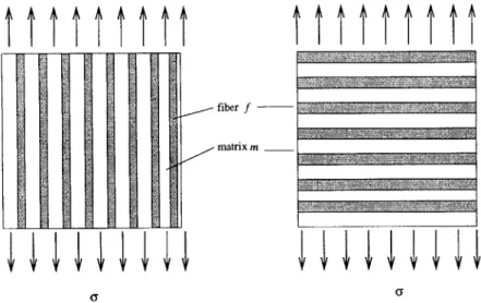
(a) unidirectional (b) woven (c) random
Figure 2-2: Fiber types based on orientation, after (Hull and Clyne, 1996)
Forms of Fiber Reinforcement
FRP composites can be produced in various types depending on the volume fraction, length, orientation, and type of fibers in the matrix (Hull and Clyne, 1996; Jang, 1994). The fibers may be continuous or in short lengths and can be aligned in one or more directions or randomly distributed in two or three dimensions. A "laminate" is a term used for the most common form of composite in structural applications. It can be fabricated by stacking a number of thin layers of unidirectional laminae and consolidating them into the desired thickness. Maximum strength and stiffness characteristics are achieved in the fiber axis direction when all the fibers are unidirectional as shown in Figure 2-2(a). This arrangement is highly anisotropic and is suited for applications where the laminate is subjected to tension in the fiber direction only. To obtain more orthotropic properties, alternate layers of fibers may vary between 0 and 900, resulting in less directionality and decreased properties in the
absolute fiber direction. As an alternate to stacking of unidirectional layers, continuous fibers can be produced using weaving, braiding, and knitting, such as the woven fabric illustrated in Figure 2-2(b). Another commonly used form of fiber distribution is random orientation
of short fibers as shown in Figure 2-2(c).
Rovings, Tows, and Fabrics Rovings, tows, and fabrics are the most commonly supplied forms of fiber for infrastructure applications. The braiding process keeps the fibers aligned
Table 2.2: Selected properties for different types of resins, from (Hull and Clyne, 1996)
Matrix Density Young's Poisson's Tensile Failure
p modulus raio strength strain
[Mg/m
3]
[GPa]
v [GPa][%]
Epoxy resin 1.1-1.4 3-6 0.38-0.40 0.035-0.1 1-6 Polyesters 1.2-1.5 2.0-4.5 0.37-0.39 0.04-0.09 2 Naylon 1.14 1.4-2.8 0.3 0.06-0.07 40-80 Polypropylene 0.9 1.0-1.4 0.3 0.02-0.04 300 PEEK 1.26-1.32 3.6 0.3 0.17 50Continuous Strands Continuous strand products are formed by swirling continuous strands of fiber with a chemical binder that holds the fiber in place. Continuous strands have higher strength and are used in modeling and pultrusion processes such as the FRP laminates predominantly used in retrofit of reinforced concrete structures.
Woven Fabrics Woven fabrics are manufactured on looms in a wide variety of weights,
weaves, and widths. Woven fabrics have lower tensile strengths than separate laminates due to fiber crimping in the weaved geometry; under tensile loading, these fibers straighten out and cause stress within the matrix system. For this reason, woven fabrics are not widely used in structural retrofitting.
Resins
The purpose of the resin matrix is to impregate the reinforcing fibers, fix them in place, and provide a shear path between the fibers to effectively transfer load. Common resin matrixes can be grouped into classes of epoxy, vinylester, and polyester. Epoxy resins are popular with concrete FRP retrofitting materials because FRP sheets can be manufactured and delivered in advanced cure states called "prepregs". Fiber impregnation can be processed through both thermosetting or thermoplastic polymers. Thermosetting matrix polymers do not require high temperature or pressure to obtain good fiber wetting, and have become the material of choice for most structural composite applications. Selected properties for different types of resins are given in Table 2.2.
Polyesters Thermosetting polyesters have traditionally been the most popular FRP ma-trix due to their low cost, ease of handling, and good electrical, mechanical, and chemical properties. Cure of thermoset polyesters is exothermic as the crosslinking molecules release heat. Both ambient and elevated cure temperature cure thermosets are available.
Epoxies Epoxy resins are popular in infrastructure projects due to their excellent adhesion properties to concrete and their toughness. Epoxies are more expensive than polyesters, but generally offer less shrinkage and higher strength and stiffness properties. Other advantages include excellent corrosion resistance and adaptability to most composite manufacturing pro-cesses.
To date, carbon fiber pre-impregnated with epoxy matrix based FRP laminates are the most popular choice of concrete FRP retrofitting materials. These are characterized
by excellent corrosion resistance, excellent resistance to fatigue, high specific stiffness and
strength, and low thermal coefficient of expansion, as well as ease of application. The most common form of fiber-reinforced composites used in structural applications are called "laminates". Laminates are made by stacking a number of thin layers of fibers and matrix and consolidating them into desired thicknesses. Both manufacturers and research laboratories are making rapid improvements in the mechanical properties and production costs of carbon fiber laminates. Figure 2-3 shows carbon fiber prices should reach $5 per pound by the turn
of the century.
2.1.2
Adhesives
The purpose of the adhesive is to provide a shear load path between the concrete surface and the reinforcing laminate. Adhesives are usually recommended by the systems manufac-turer for use with the FRP laminate from the general classes of epoxy, vinylester, polyester, urethane, and other materials. Selection is based on issues including compatibility and bond strength to the substrate, and resistance to environmental effects such as moisture, salt water, and temperature fluctuations. Commonly used adhesives are modulus, high-strength structural epoxy pastes that conform to industry standards such as ASTM C-881
150-100 -lr volume, millions of 50 - . . pounds per year 1970 1980 1990 2000 year
Figure 2 3 Carbon fiber prices and volume produced over last two decades
Standard Specification for Epoxy-Resin-Base Bonding Systems for Concrete, and AASHTO M-235 Epoxy Resin Adhesives.
Raw materials used in most epoxy adhesives are low-molecular-weight organic liquid resins containing epoxide groups (ACI Committee 440R, 1996). The epoxide group consists of rings of one oxygen atom and two carbon atoms. The most common base material used to produce epoxy resin is diglycidyl ether or bispheno-A (DGEBA), which contains two epoxide groups, one at each end of the molecule. Other materials that can be mixed with the starting liquid include dilutents to reduce viscosity and flexibilizers to improve impact strength of the cured epoxy adhesive.
Cross-linking of the epoxy is initiated by use of a hardener or reactive curing agent. A wide variety of agents are available, including diethylenetriamine (DETA). As the reaction of the hardener and the base molecules occur, DGEBA molecules cross-link with each other and a network is formed, creating the solid cured matrix of epoxy adhesive. Through this process, good adhesion with the substrate is achieved through mechanical interlocking, par-ticularly with porous and rough substrates such as concrete. Curing time and increased temperature required to complete cross-linking depend on the type and amount of hard-ener used. Some hardhard-eners will work at room temperature; however, most hardhard-eners require elevated temperatures to cure.
Epoxy adhesives provide the following general performance characteristics:
e A range of mechanical and physical properties can be obtained through diversity of
input materials,
o Volatile compounds are not emitted during curing and processing, o Low shrinkage during cure,
o Excellent resistance to chemicals and solvents, and
o Good adhesion to a number of fillers, fibers, and substrates, including concrete.
Figure 2-4 shows the effects of various epoxy matrix formulations on the stress-strain re-sponse of the matrix (Schwartz, 1997). There are some drawbacks associated with the use of epoxy adhesives:
o Costs are generally higher than for polyester or vinylester adhesives, o Epoxies must be carefully processed to maintain moisture resistance,
o Curing times can be lengthy, and
o Some hardeners can require special precautions in handling, and resin and some hard-eners can cause skin sensitivity reactions in production operations.
2.1.3
Manufacturers
The growing Unites States retrofit market is currently dominated by a limited number of manufacturers and contractors. Fyfe Co. LLC is the inventor and manufacturer of the Tyfo carbon fiber system, and also provides preliminary engineering and budgeting information. MasterBuilders, Inc. manufactures the MBrace composite strengthening system, which is available with high strength carbon, high modulus carbon, and E-Glass fibers. Sika Corpo-ration manufactures the CarboDur system, a pultruded carbon fiber laminate designed for strengthening concrete, timber, and masonry structures. Hexcel Corporation is a materials
ksi MPa 20 13-16 11( 12 83 INTERMEDIATE MODULUS U) cc) a 55 -LOW MODULUS 4 27 .-0 0.01 0.02 0.03 0.04 0.05 0.06 0.07
STRAIN in./in. and mm/mm
Figure 2-4: Stress-strain diagram for three epoxy materials, after (Schwartz, 1996)
manufacturer that has formed a global alliance with Sika Corporation to develop and mar-ket the CarboDur carbon fiber composite strengthening system. A brief review of additional manufacturers can be organized by geographic location (ACI Committee 440R, 1996).
North America In North America, production of composites has generally been limited to FRP reinforcing bars for concrete. Nine companies are involved in this area, including Autocon Composites, Corrosion Proof Products, Creative Pultrusions, International Grat-ing, Marshall Industries Composites, Marshall-Vega Corporation, Polystructures, Polygon, and Pultrall. Current producers offer a pultruded FRP bar made of E-glass with choice of thermoset resin.
Japan Japanese corporations provide a wide range of configurations including smooth bars and plates, deformed bars, tapes, meshes, nets, and webs. CFCC is a stranded cable produced by Tokyo Rope, a manufacturer of prestressing steel tendons. Leadline is a type of carbon FRP prestressing bar produced by Mitsubishi Chemical with their Dialead fiber material. FiBRA is an aramid material developed by Mitsubishi Construction consisting of braided epoxy-impregnated strands. NEFMAC is a 2D grid-type reinforcement consisting of glass and carbon fibers impregnated with resin developed by Shimizu Corporation. A