Design and Analysis of a Permanent Magnet Generator for Naval Applications by
Jonathan E. Rucker
Masters in Business Administration
Kenan-Flagler Business School, University of North Carolina at Chapel Hill, 2001
B.S.E., Electrical Engineering
Duke University, 1994
Submitted to the Department of Ocean Engineering and the Department of Electrical Engineering and Computer Science in Partial Fulfillment of the Requirements for the Degrees of
Naval Engineer and
Master of Science in Electrical Engineering and Computer Science at the
Massachusetts Institute of Technology June 2005
2005 Jonathan E. Rucker. All rights reserved.
The author hereby grants to MIT permission to reproduce and to distribute publicly paper and electronic copies of this thesis qocument in whole or in part.
Signature of Author Certified by Certified by Accepted by Accepted by C MASSACHU
Department of Ocean Engineering and the Department of Electrical Engineering and Computer Science May 11, 2005
. James Kirtley, Professor of Electrical Engineering
Department of Elecqrical Engineering and Computer Science
Tesis Supervisor
Timothy J. McCoy, Assoiatprof gsorg[ Na l Con ction and Engineering
4 epar me of Ocean Engineering Thesis Reader
i fy essor of Ocean Engineering
'hair, De tnu Gtteeofraduate Students
Depajwixl ofpc4IEngineering Arthur C. Smilh, Professor of Electrical Engineering and Computer Science Chair, Departmental Committee on Graduate Students
SETTS INST TTJTE Department of Electrical Engineering and Computer Science
OF TECHNOLOGY
Design and Analysis of a Permanent Magnet Generator for Naval Applications by
Jonathan E. Rucker
May 11, 2005
Submitted to the Department of Ocean Engineering and the Department of Electrical Engineering and Computer Science in Partial Fulfillment of the Requirements for the Degrees of
Naval Engineer and
Master of Science in Electrical Engineering and Computer Science
ABSTRACT
This paper discusses the electrical and magnetic design and analysis of a permanent magnet generation module for naval applications. Numerous design issues are addressed and several issues are raised about the potential improvements a PM generation system can offer. A proposed 16 MW PM generation module design is presented along with a detailed design methodology.
Eighty different machines and power conversion modules are sized, designed, and analyzed with a final design selected. Specifically, sizing and detailed machine design and analysis is performed examining the effects of numerous parameters including number of phases, number of poles, magnetic geometry, machine dimensions, and material types. Analytical models are developed to study rotor losses caused by stator winding time and space harmonics and slot space harmonics. Power electronics and conversion modules to connect the high-speed generator to a DC distribution system are designed and analyzed. In depth simulation of the eighty complete systems is performed using the software programs MATLAB (Version 12.0, Mathworks) and PSIM (Version 6.0, Powersim, Inc.).
The 16 MW permanent magnet generation module, consisting of the generator and associated power electronics, provides an excellent alternative to traditional wound rotor synchronous machines. The final design offers significant reductions in both weight and volume. Specifically, it is estimated that the PM generation module has a 7x reduction in volume and a lOx reduction in weight compared to similarly rated wound rotor systems. These reductions can provide flexibility to naval architects since power, weight, and volume are integral parts of the design and construction processes. However, further study is necessary to verify the PM generation modules thermal, structural, and mechanical performance.
Thesis Supervisor: James Kirtley
Title: Professor of Electrical Engineering Thesis Reader: Timothy J. McCoy
Table of Contents
Table of Contents ... 5 List of Figures ... 9 List of Tables ... 11 Chapter 1 Introduction... 13 1.1 Purpose... 13 1.2 Problem ... 13 1.3 Background ... 14 1.3.1 H istory... 141.3.2 Pow er G eneration & D istribution ... 15
1.4 Scope... 17
Chapter 2 Pow er Requirem ents and M achine Selection ... 19
2.1 M achine & M odule Requirem ents... 19
2.2 M achine Selection... 19
2.2.1 Perm anent M agnet versus W ound Rotor ... 20
2.2.2 Type of Perm anent M agnet M achine... 23
Chapter 3 M aterial Selection and M achine Initial D esign ... 27
3.1 M aterial Selection ... 27
3.1.1 Perm anent M agnets... 27
3.1.2 Stator and Rotor M aterial... 30
3.2 M achine D esign Param eters ... 31
3.2.1 Stator M echanical D esign... 31
3.2.2 Rotor M echanical D esign ... 34
3.2.3 N um ber of Poles and M agnet Pole D esign ... 35
3.2.4 M agnetic D im ensions ... 36
3.2.5 N um ber of Phases ... 37
3.2.6 Slots per Pole per Phase... 38
3.2.7 Stator W indings ... 39
3.3 M achine C alculated Param eters... 41
3.3.1 Basic M odel ... 41
3.3.2 W inding Resistances ... 41
3.3.3 W inding & M agnet Factors ... 42
3.3.4 Flux and V oltage... 44
3.3.5 M achine Inductances ... 47
3.3.6 Basic Losses... 49
3.4 M achine Sizing M ethods ... 52
3.4.1 B asic Sizing M ethod... 52
3.4.2 D etailed Sizing M ethod O ne... 53
3.4.3 D etailed Sizing M ethod Tw o ... 56
3.4.4 Com parison of M ethods... 60
Chapter 4 Pow er Electronics and Conversion ... 61
4.1 Background... 61
4.2 Rectification... 62
4.3.1 Buck Converter ... 64
4.3.2 Output Filter... 65
4.3.3 Input Filter ... 66
4.3.4 Converter Control ... 69
4.4 Conversion Losses ... 72
4.5 Com ponent Sizes and W eights ... 73
Chapter 5 Waveforms, Models, and Machine/Module Optimization ... 77
5.1 Initial Generator W aveform s ... 77
5.2 Rotational Stress and Retaining Sleeve ... 80
5.3 Rotor Losses... 82
5.3.1 Model for Time Harmonics & Winding Space Harmonics ... 82
5.3.2 M odel for Stator Slot Effects ... 91
5.4 Com plete System M odel & Design Procedure ... 93
5.5 Optim ization ... 95
Chapter 6 Results and Analysis... 97
6.1 General... 97
6.2 N um ber of Phases ... 98
6.3 Retaining M aterial ... 101
6.4 N um ber of Poles ... 104
6.5 Final Power M odule... 107
6.5.1 PM Generator... 107
6.5.2 Power Electronics M odule... 109
6.5.3 Perform ance/W aveform s ... 111
6.6 Com parison... 115
Chapter 7 Conclusions and Recom m endations ... 117
7.1 Design Lessons Learned ... 117
7.1.1 PM Generator... 117
7.1.2 Power Electronics ... 119
7.2 Power Generation M odule ... 120
7.3 Recom m endations/Further Study... 121
Glossary ... 123
Acknow ledgem ents... 127
List of References ... 129 Appendix A. Appendix B. Appendix C. Appendix D. Appendix E. Appendix F. Appendix G. Appendix H. Appendix I. Appendix J. Appendix K. Appendix L. Appendix M. D etailed Pow er Requirem ents... 135
MATLAB Code: Basic Sizing Method... 139
PM M achine D atabase ... 14 1 MATLAB Code: Sizing Method 1 ... 143
MATLAB Code: Sizing Method 2 ... 151
M A TLA B Code: B ode Plot ... 159
MATLAB Code: PM Generator Waveforms... 161
MATLAB Code: Retaining Sleeve Stress Calculations ... 165
MATLAB Code: Rotor Losses from Winding Time and Space Harmonics ... 167
MATLAB Code: Rotor Losses from Slot Effects... 171
Results for PM Machine Variants... 175
Results for Power Conversion Module Variants ... 177
Appendix N. Appendix 0. Appendix P.
Results for Power Module Weights ... 181
Rectifier/Input Filter Mass and Volume Calculations ... 183
List of Figures
Figure 1: Typical Turbine Generator System ... 16
Figure 2: Example of W ound Rotor Generator... 20
Figure 3: Cross Section of W ound Rotor Generator... 21
Figure 4: Example of PM Generator... 22
Figure 5: Flux vs. Number of Poles ... 22
Figure 6: Example of Inner Rotor PM M achine ... 24
Figure 7: Example of Outer Rotor PM M achine ... 25
Figure 8: Example of Axial Flux PM M achine ... 25
Figure 9: Example of B-H Curve... 27
Figure 10: Typical M agnet B-H Curves ... 29
Figure 11: Slotless Stator Design... 31
Figure 12: Slotted Stator Design... 32
Figure 13: Stator Slot Geometry... 33
Figure 14: Example of Form-W ound W inding... 40
Figure 15: Per Phase M odel... 41
Figure 16: Short-Pitch Coil... 42
Figure 17: W inding Breadth ... 43
Figure 18: Air Gap Flux Density ... 45
Figure 19: Core Loss Data... 50
Figure 20: Voltage Vector Relationship ... 55
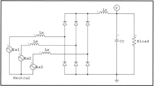
Figure 21: Basic System Layout ... 61
Figure 22: Basic 3-phase Rectifier... 63
Figure 23: Basic Buck Converter... 64
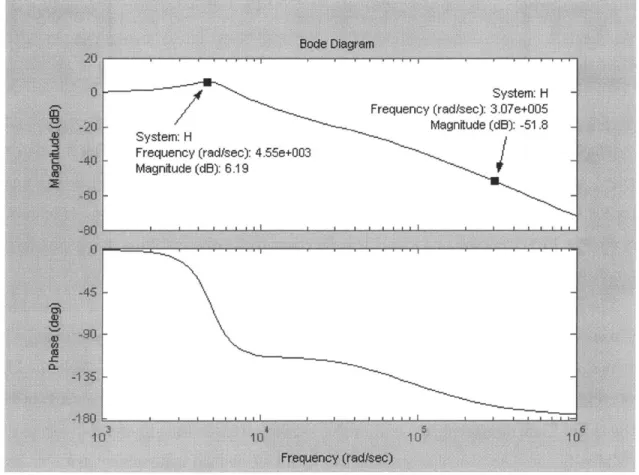
Figure 24: Bode Plot for Converter Input Filter ... 69
Figure 25: Block Diagram of Control Scheme ... 70
Figure 26: Transistor Switching Losses... 73
Figure 27: Initial Generator Flux Density W aveform ... 78
Figure 28: Initial Generator EM F W aveform ... 79
Figure 29: Initial Generator Harmonic Content... 79
Figure 30: Retaining Sleeve Hoop Stress ... 80
Figure 31: General M agnet Loss M odel... 83
Figure 32: Layer of M aterial... 83
Figure 33: Relevant Harmonics ... 91
Figure 34: Retaining Sleeve Induced Currents... 91
Figure 35: Flux Density Variation ... 92
Figure 36: System M odel... 94
Figure 37: M achine Optimization Parameters ... 96
Figure 38: W eights vs. Number of Phases... 98
Figure 39: M achine Losses vs. Number of Phases ... 99
Figure 40: PCM Losses vs. Number of Phases... 100
Figure 41: THD vs. Number of Phases ... 101
Figure 42: W eights vs. Retaining Sleeve M aterial ... 102
Figure 44: PCM Losses vs. Retaining Sleeve M aterial ... 103
Figure 45: THD vs. Retaining Sleeve M aterial ... 104
Figure 46: W eights vs. Num ber of Poles ... 105
Figure 47: M achine Losses vs. Num ber of Poles ... 105
Figure 48: PCM Losses vs. Num ber of Poles ... 106
Figure 49: THD vs. Num ber of Poles ... 107
Figure 50: Diagram of PM Generator Final Design ... 109
Figure 51: Power M odule Final Design Diagram ... 110
Figure 52: PM Generator Voltage W aveform s... 111
Figure 53: Output Voltage (16 M W )... 112
Figure 54: Output Current (16 M W ) ... 112
Figure 55: AC Line Current (16 M W )... 113
Figure 56: Output Voltage (100 kW )... 114
Figure 57: Output Current (100 kW ) ... 114
List of Tables
Table 1: Examples of Current Generator Characteristics ... 16
Table 2: General M achine & M odule Requirements... 20
Table 3: Comparison of W ound Rotor and PM Generators ... 23
Table 4: M agnet M aterial Properties ... 28
Table 5: Selected M agnet Properties ... 29
Table 6: Lam inated Steel Properties ... 31
Table 7: Stator Current Densities... 33
Table 8: Core Loss Parameters ... 51
Table 9: Air Gap Shear Stress Values... 52
Table 10: Input Parameters for Sizing M ethod 1... 53
Table 11: Input Parameters for Sizing M ethod 2... 57
Table 12: Buck Converter Load Values... 65
Table 13: Power Electronics M odule Component Characteristics ... 74
Table 14: Retaining Sleeve M aterials ... 81
Table 15: General M odule Specifications... 97
Table 16: General M odule Results ... 97
Table 17: PM Generator Final Design Parameters ... 108
Table 18: W inding Layout ... 109
Table 19: PCM Final Design Parameters... 110
Table 20: Comparison of M achines/M odules... 115
Table 21: Ship Connected Loads ... 135
Chapter 1 Introduction
1.1 PurposeThe purpose of this thesis is to design and analyze a permanent magnet generator and power module for naval applications. When deciding whether to implement an electrical
technology or component onto a naval vessel, the size, weight, and cost are the major factors for successful integration. Significant performance improvements and cost reduction of power electronics, coupled with the availability and decreasing cost of high energy permanent magnet (PM) materials makes PM generators attractive for naval usage. These machines offer numerous desirable features, including light weight, small size, simple mechanical construction, easy maintenance, good reliability, and high efficiency [1].
Before analysis of a generator can begin, it must be properly designed for typical naval power requirements. This involves sizing the generator along with designing the associated power electronics for connecting the machine to the distribution system. A specific concern associated with PM generators is possible inefficiencies and excessive heating; in particular rotor losses caused by space and time harmonics during the energy conversion processes. The
optimum machine design is one that delivers the required power through a matching process between the generator and the power electronic converter [2].
1.2 Problem
The Navy's commitment to develop an integrated electric power system for the next generation warships offers the expectation of using the installed generation capacity to power ship propulsion, advanced weapons components, and high power combat control systems [3]. As these electrical loads increase, it becomes increasingly important to efficiently utilize installed power as well as develop smaller, effective power generation systems. Navy ships are extremely high performance systems and therefore power and weight considerations are integral parts of the design process.
The life cycle of a navy ship is on average 2-3 times longer than a commercial ship and therefore navy ships undergo excessive modernization and upgrades throughout their service life. Many of the newer components have significantly higher power requirements than the originals
putting a burden on the power generation system. Therefore, the Navy is moving toward
designing all electric ships with integrated power systems (IPS) and increased power generation that can be efficiently managed to meet future demands.
The effective integration of electrical power in future naval ships requires the development of technologies that ensure volume and mass reduction in critical mechanisms. Military ships require higher power density components, impose more stringent acoustic and EM signature requirements, and subject systems to harsher environments than commercial
applications [4]. Rotating generators, coupled with prime movers, need to be lighter in weight and higher in power density. High-speed PM generators provide a substantial reduction in size and weight making them a logical choice for naval applications. Currently, the Navy has not designed or built a high power (megawatt) PM generator and therefore the need exists.
In conjunction with constructing a PM generator, a DC bus architecture is one of the
preferred schemes for the future [5]. DC power distribution systems can offer a size and weight
reduction compared to high-power AC systems [3]. With a DC bus distribution, the PM generator can be optimized independent of producing 60 Hz frequency as required in the past. However, conversion of the high-frequency generator AC output to DC requires power
electronics. Rectification of AC to DC presents the problem of creating harmonics in the input current which are then reflected back onto the generator causing rotor losses. In addition, the generator produces space harmonics which also produce losses in the rotor. Therefore, the PM generator and power electronics module (PEM) need to de designed and optimized to deliver constant DC power while minimizing machine losses.
1.3 Background 1.3.1 History
The Navy has designed and built electric ships since the early part of the 20th century. The original advantages perceived for electric ships, superior performance, reduced manning, arrangement flexibility, and fuel efficiency, are still relevant today [6]. In the early part of the 20th century, diesel-electric submarines, small surface ships, and some battleships and carriers had electric propulsion. By the late 1940s, mechanical drive systems became popular because of improvements in metallurgy and manufacturing. However, the capability of mechanical
transmissions reached its limits in the late 20th century spawning a renewed interest in electric drive and integrated power systems for military applications.
For the last thirty years, the commercial industry has designed and operated integrated power systems (IPS). An IPS is a ship architectural paradigm in which the ship's power and
propulsion are provided by a common electrical distribution system instead of having a separate mechanical drive for propulsion. For military applications, an IPS provides numerous benefits:
* Decreased life cycle costs because of increased fuel economy and efficiency (a Navy ship with IPS may consume 10-25% less fuel than a similar ship with mechanical drive [7])
" Increased ship design and arrangement flexibility since the ship is not limited to having a
long mechanical shaft line
" Reduced system complexity
" Higher degree of modular design using power components " Broad industrial base for implementing IPS design
" High levels of automation and control
" Increased power available for non-propulsion uses since a Navy ship spends a large
portion of its time operating at low propulsion levels (approximately 95% of the time) * Increased stealth, survivability, and payload
Since an IPS provides power for both the ship loads and propulsion, larger generation capability is required. As the Navy builds its new ships with IPS architectures, compact, high-power generation systems must be examined to help facilitate implementation of the new designs.
1.3.2 Power Generation & Distribution
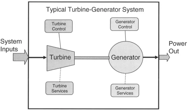
Almost all naval core power generators to date are air-cooled 50/60 Hz machines that are military derivatives of commercial generators and are therefore size and weight excessive [8]. A typical turbine generator system is shown in Figure 1 and Table 1 contains nominal
System
Inputs
V
Typical Turbine-Generator System
Turbine Generator
Control Control
Generator Services
Figure 1: Typical Turbine Generator System
Table 1: Examples of Current Generator Characteristics
1 3 21 3600 4.7 4 3.4 50.0
2 3 36.5 3600 6.2 4.37 3.76 63.6
3 3 26 3600 6.2 3.56 4.5 68.1
4 3 25 3600 5.18 3.1 4.15 57.3
With the advent of high-power, cost-effective power electronics, it is no longer necessary to generate power at 50/60 Hz so generators can be optimized independent of frequency. High-speed, power-dense generators become the logical choice for naval purposes. Permanent magnet machines are ideal for this high-speed application due to their simple structure and high power density [9].
Since the generator can now be designed to produce higher frequencies, distribution architectures are not limited to being 60 Hz. Either a high frequency AC system or a DC system can be designed through the use of power electronics modules, with the DC distribution being preferred because of its advantages in size and weight. In this thesis, a high-power DC zonal architecture is assumed using solid state converters to generate AC where needed. Each zone is
Power
Out
electronically isolated from the other zones with automatic fault detection and reconfiguration to provide continuous power during damaged conditions. The PM generator sets and power
electronic conversion modules serve as the backbone thereby providing a reliable power system for navy ships.
1.4 Scope
The scope of this thesis is limited to the PM generator and associated power electronics
AC-DC conversion module. The following is accomplished:
" Determine the electrical power requirements for a Navy IPS ship in order to properly size
the generator
* Compare typical wound rotor machine design to a permanent magnet design to determine applicability for IPS applications
" Conduct material analysis and selection for the generator design " Perform initial PM generator detailed design
* Design the power electronics conversion module to perform high-power AC-DC conversion
* Conduct detailed analysis of rotor losses of the PM generator, in particular those caused
by time and space harmonics
" Perform numerous iterations of machine and power electronics designs to develop
Chapter 2 Power Requirements and Machine Selection
2.1 Machine & Module RequirementsOn board Navy ships, electricity is used to provide power to virtually all components, including mission systems, support systems, combat systems, and communications systems. In addition, as ships continue to be upgraded and modernized, more power is needed for newer combat systems and weapons components. Most current naval platforms have some form of mechanical propulsion system with separate ship service electrical generators supplying the ship's power. With an IPS ship, the ship's generators provide power for propulsion and the ship's service loads, and through proper utilization, power is efficiently managed.
To properly size the PM generator, the power requirements must be identified and therefore a typical load list is developed for an IPS naval ship and is included in Appendix A. The overall power requirement for the generator is 16 MW. Since size and weight are important factors and the generator can be optimized independent of frequency, high-speed operation and maximum power-density are desired. Therefore, the highest possible speed is selected while ensuring the PM generator is compatible with both gas turbines and steam turbines.
Traditionally, gas turbines run at much higher speeds than steam turbines causing the steam turbines to be more limiting. From information collected from the Elliot Turbomachinery Company, Inc., 16,000 RPM is approximately the highest speed steam turbine that can
reasonably be constructed at the megawatt power level [13]. Therefore, to provide a degree of conservatism, 13,000 RPM is selected for the nominal design speed for the PM generator.
The power electronics module (PEM) converts the AC voltage from the generator to
700 VDC. Overall, the PEM and generator must be designed so that losses suffered by the
permanent magnets on the generator rotor are minimal. Table 2 lists the general requirements for the entire system.
2.2 Machine Selection
Military ships require high power density components and improved acoustic and
electromagnetic signature requirements while subjecting systems to harsh environments [14]. It is therefore important to ensure the power generation system is capable and efficient.
Table 2: General Machine & Module Requirements
Generator Power 16 MW
Generator Speed 13,000 RPM
PEM Output Voltage 700 5 VDC
PEM Output Ripple 0.7 VDC (@ 16 MW)
Generator Rotor Losses Minimal
2.2.1 Permanent Magnet versus Wound Rotor
Reducing the size and weight of ship's turbine generator sets offers significant
advantages to naval architects. Replacing older generators with lightweight ones could make it possible to decrease the size of some generator sets by as much as 50% [15]. PM generators therefore become an attractive alternative compared to wound rotor machines because of the availability and decreasing cost of high energy PM materials along with improved power electronics.
A wound rotor generator normally consists of armature windings on a stationary stator
frame with field windings on an inner rotor. The rotor is turned by a prime mover, usually a gas or steam turbine, and current is supplied to the field windings through brushes or a brushless exciter. As the current-carrying field windings rotate past the stator windings, current is
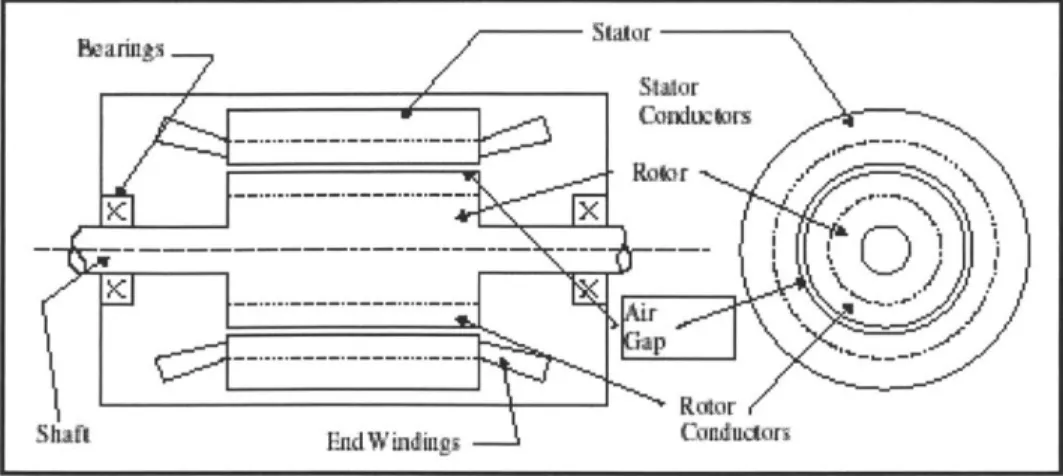
produced in the stator windings through Faraday's Law. An example of a wound rotor machine is shown in Figure 2 [8] and Figure 3 [16].
Figure 3: Cross Section of Wound Rotor Generator
Wound rotor generators have been the backbone of power generation for the U. S. Navy because they are a proven technology that is battle tested. They offer steady voltage regulation using the field windings, a large air gap for producing the rotor magnetic flux, low fault currents, and high power capabilities.
However, the machines tend to be complex, weight excessive, and they require field windings which limit design alternatives. There are several drivers which cause these problems to occur. First, to generate the necessary magnetic flux levels, wound rotor generators have large pole pitches to support the required field windings. These pole pitch windings in turn require larger end turns and thick back iron to support the magnetic flux, both of which contribute to increased size. Second, because of the winding losses in the rotor, large cooling systems can be required thus increasing the number of support components.
High speed generators offer a reduction in machine size and weight because as a machine's speed increases, its size decreases for a given output power. The PM generator is ideal for high-speed applications because of its simple structure and high power density [9]. In a PM generator, the rotor field windings are replaced by permanent magnets which do not require additional excitation. As the permanent magnets are rotated by the prime mover, current is produced in the stator windings. An example of a PM generator is shown in Figure 4 [8].
7staor
Ra tor
UquId-cocled sUtcr
Figure 4: Example of PM Generator
PM generators offer several advantages: they have no rotor windings so they are less complicated; they have high efficiencies; the gap field flux is not dependent on large pole pitches so the machine requires less back iron and can have a greater number of smaller poles; and they usually require smaller and fewer support systems. Assuming the same flux density and
circumferential arc, doubling the number of poles produces the same radial flux but requires half
the stator core thickness, as shown in Figure 5.
Half Stator Core Thickness
-Same Radial Flux
4
SHowever, PM generators also have some disadvantages. They do not possess field excitation control and therefore voltage regulation can be problematic. This can be corrected by using external voltage control such as large capacitor banks or power electronics, as well as choosing the turns on the stator winding properly to produce the anticipated required nominal voltage. Additionally, since the permanent magnet fields cannot be turned off, there exists the risk of excessive currents in the event of an internal fault. This problem can also be solved through the design of the turbine governor and controller or dynamic braking. Overall, the advantages of the PM generator over the traditional wound rotor generator make it a better alternative for high-speed navy applications. A summary comparing the different designs is given in Table 3.
Table 3: Comparison of Wound Rotor and PM Generators
Steady voltage regulation with Weight excessive
field windings
High power capabilities Lar e size
Wound Rotor Rotor windings & associated
Large air gap for flux Roowidns&aoctelosses
Low fault currents Lar e su ort s stems
Proven, robust design
Less complicated regulation
Reduced size and weight Potential fault currents
Permanent Magnet High efficiency Ma net losses
No excitation supply or field windings
High speed aplicability
2.2.2 Type of Permanent Magnet Machine
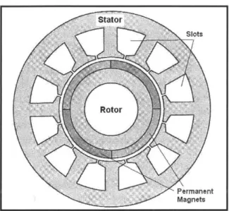
There are numerous layout possibilities for permanent magnet machines and only the most common are discussed here. These include radial flux inner rotor, radial flux outer rotor, and axial flux designs. In most PM machines, flux crosses from the rotor to the stator in the radial direction [17]. The first type, the radial flux inner rotor design, is the closest configuration to the classical AC synchronous generator. An example of this design is shown in Figure 6 [17].
Stator
-Slots
Rotor
Permanent
Magnets
Figure 6: Example of Inner Rotor PM Machine
In this type of machine, the windings are placed on the stator, either in slots or in a slotless ring, and the magnets are surface mounted on the rotor or buried in the rotor. Buried magnet designs often result in rotors that are larger than equivalent surface-magnet machines with high-energy magnets [18]. Buried magnet machines can also have significant structural issues in high-power applications [19]. When the magnets are surface mounted and the machine is operated at high speed, the magnets are often secured with a retaining device made of either alloy steel or carbon-fiber. Overall, the inner rotor machine possesses high torque/power capability and good heat conduction and cooling properties making it ideal for high-speed, higher-power applications [18].
The radial flux outer rotor machines are commonly used in hard disk drives, small computer ventilation fans, and some blowers. This type of design is very efficient, low-cost, easy to manufacture, and applicable for low-power applications [18]. It is the opposite of the inner rotor because the stator in on the inside with the rotor and magnets on the outside. A cross section of an outer rotor machine is shown in Figure 7 [17].
Figure 7: Example of Outer Rotor PM Machine
The axial flux machine is significantly different than the previous two because flux flows in the axial direction vice radial direction and the windings are oriented radially vice axially (see Figure 8 for an example diagram [20]).
Figure 8: Example of Axial Flux PM Machine
The main advantages of this design are their low cost, flat shape, and smooth rotation. However, if axial-flux machines are operated at high speeds (above 1000 RPM), eddy-current losses and heating can become excessive [18]. Also, stator construction is difficult because it must be laminated circumferentially. An example of this design is the turntable for a record player.
Rotor
Slots
Stator
Permanent Magnet
Overall, because of its inherent advantages in heat removal and cooling, the abundance of manufacturing capabilities, and its high-power, high-speed applicability, the radial flux inner rotor with surface mounted magnets is selected for the 16 MW PM generator design.
Chapter 3 Material Selection and Machine Initial Design
3.1 Material Selection
One of the key considerations during the electromagnetic, structural, and thermal design of a permanent-magnet machine is the selection of the magnet, stator, and rotor materials [21]. Machine output, heat rise, weight, and cost are a few of the characteristics which are directly influenced by selection of the machine materials [22].
3.1.1 Permanent Magnets
The size and performance of high-speed PM generators depend on the permanent magnet material properties [9]. The magnets must be selected to provide the necessary air gap magnetic field and ample coercive force to compensate for possible damaging effects while minimizing the volume of material because of cost and weight considerations [23].
Ferromagnetic materials are the most common substances used in the construction of machines and their properties are normally described using B-H curves and hysteresis loops. These curves represent an average material characteristic that reflects the non-linear property of the permeability of the material but ignores the multi-valued properties [17]. An example of a B-H curve is shown in Figure 9.
LoadLine B (Tesia)
Bind L n
Hk initial
Magnetization
Hc
rRe coil Line H krm
Br: Remnant Flux Density Hc: Coercivity
Bmn: Magnet Flux Density Hk: Limiting/knee magnetizing force
Several basic magnetic properties are of critical importance for the permanent magnets in a PM machine:
* Remnant Flux Density (Br): It is the value of the flux density remaining after magnetization and it directly influences the air gap flux and magnet sizes.
* Coercivity (He): It is the value of magnetizing field needed to reduce the flux density in
the magnet to zero and it gives a first order estimate of a magnet's resistance to demagnetization.
* Energy Product (BHmax): It is the maximum energy product of the magnet and it is inversely proportional to the total magnet volume required.
* Recoil Permeability (prec): It is the gradient of the B-H curve and it gives the magnet's ability to return to its initial magnetization after subjected to damaging forces. If the
magnet goes below Hk, then it will recoil along a lower line resulting in a lower magnet
flux density.
* Load Line: It is a line drawn from the origin to the magnet operating point on the hysteresis curve (B.). The magnitude of the slope of the load line is the permeance coefficient.
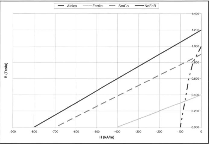
Permanent magnet materials come in many varieties and the four most common types for machine applications are Alnico, Ferrites, SmCo material, and NdFeB material. Table 4 and Figure 10 show the characteristics and typical B-H curves for these materials [18].
Table 4: Magnet Material Properties
Remanence (Br) T 0.6 - 1.3 0.35 -0.43 0.7 - 1.05 1.0- 1.3
Coercivity (He) kA/m 40-130 180-400 800-1500 800-1900
Recoil Permeability 1.9-7 1.05 - 1.15 1.02- 1.07 1.04- 1.1
(prec)
Energy Product (BHmax) kJ/m3 20- 100 24-36 140 - 220 180 - 320
Maximum Temperature C 500 - 550 250 250 - 350 100 - 200
Br Temperature %/0C -0.01 to -0.02 -0.2 -0.05 -0.08 to -0.15
Coefficient
The rare-earth magnets, SmCo and NdFeB, have become more popular for high performance applications because of their greater power density, high coercivity, high flux densities, and linearity of the demagnetization curves [24].
- Alnico Ferrite - SmCo - NdFeB 1.400 a) 0 -900 -800 -700 -600 -500 -400 -300 -200 -100 H (kA/m)
Figure 10: Typical Magnet B-H Curves
Between the two rare-earth permanent magnets, NdFeB is preferred because it is cheaper and more readily available. It does possess some adverse characteristics such as moderate corrosion and lower resistance to temperature effects, but these can be controlled using surface treatments and proper cooling [25]. Therefore, NdFeB magnets are selected for use in the PM generator with the conservatively assumed values listed in Table 5.
Table 5: Selected Magnet Properties
Remanence (Br) T 1.2
Coercivity (He) kA/m 900
Recoil Permeability (rec) 1.05
Energy Product (BHmax) kJ/m3 260
Maximum Temperature 0C 180
Resistivity pi/m 1.43
IP
0.200o
3.1.2 Stator and Rotor Material
The type of material chosen for the stator and rotor is important because it impacts the machine losses and efficiency. The rotor is usually built from the same material as the stator for ease of construction but is can be made of any economical steel provided it is strong enough for the given function [18]. No one material is optimum for every application and the normal criteria for selection are cost, permeability, core losses, and saturation flux. It is important that the material act as a flux guide and absorb the minimum amount of magnetomotive force (MMF) so that the flux is concentrated in the air gap. In addition, the material should minimize core losses including hysteresis and eddy current losses.
High-quality, non-oriented, electrical grade lamination steels are typically used in most machines because the laminations help minimize losses. The four main materials are low carbon steels, silicon (Si) steels, nickel (Ni) alloy steels, and cobalt (Co) alloy steels. Low carbon steels are the lowest cost and are used in high volume applications where high core losses are
acceptable. Silicon steels usually have 3% silicon which increases the resistivity to reduce eddy current losses. They are selected and specified based on core loss, with each grade (M19, M27,
M36, and M43) having higher core losses and lower cost [22]. The lamination thickness is a
tradeoff between cost and performance and the most common sizes are 0.014 in, 0.0185 in, and
0.025 in (29 gauge, 26 gauge, and 24 gauge).
Nickel alloys are either 49% or 80% nickel and they have lower losses than the silicon steel but are much more expensive. In addition, they require careful handling and not suited for high flux density environments (above 0.8 T) because of saturation. The cobalt alloys are only used in extremely high-performance situations such as military aircraft and space applications because of the high cost. Table 6 summarizes the different stator materials and the M19, 29-gauge electrical silicon steel is selected for the PM generator because it is economical, its thin laminations minimize losses, and it has a saturation flux density of about 1.8 T [2], [18], [22].
Table 6: Laminated Steel Properties
Low Carbon Steel
Fair Good Good Best 0.5
Si Steel Good Good Fair Good 1.0
Thin Si Steel Better Good Fair Fair 10.0
49% Ni Alloy Good Fair High Care Req'd 12.0
80% Ni Alloy Better Low Best Care Req'd 15.0
Co Alloy Good Best Good Care Req'd 45.0
3.2 Machine Design Parameters 3.2.1 Stator Mechanical Design
The stator is an important part of the machine because it serves as the main structural component, it provides the housing for the armature windings, and it completes the flux path for the magnetic circuit. The main consideration in the mechanical design of the stator is whether to make it slotted or slotless. A slotless stator has the armature windings located in the air gap of the machine as shown in Figure 11 [19].
(Shaft)
Rotor Magnets
Figure 11: Slotless Stator Design
One of the advantages of the slotless construction is unique winding layouts are possible to meet specific performance goals. Another advantage is that the space available for the armature windings increases by a factor of about two since there are no stator teeth. This produces lower
Stator Winding
conductor losses since less current flows in each winding. The flux density is reduced, however, because the effective air gap is much larger since the windings are in the air gap. Overall, there exists a higher electrical loading and a lower magnetic loading.
One disadvantage of the slotless design is there are no good conduction paths to remove the heat generated from the windings. This reduces the allowable current density in the windings and lowers the power output. Another disadvantage is that the windings are directly exposed to the rotating flux which raises the possibility of additional eddy-current loss in the conductors and further losses due to circulating currents in the windings [18]. Overall, the performance of a slotless stator is almost always lower than that of an equivalent slotted stator design and therefore slotless stators do not appear often in high-power applications [17].
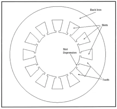
Slotted stators are the traditional stator design and consist of openings around the stator for the armature windings as shown in Figure 12 [26]. The openings provide rigid housings for the conductors and associated insulation.
Rack kfon
Slots
Stot
Depression
Figure 12: Slotted Stator Design
Stator slots vary in size and shape with the most common configurations being rectangular or trapezoidal. In this paper, the slots are assumed to be approximately rectangular as shown in Figure 13 and contain form-wound windings so that the depression width is the same as the slot top width.
+wsb
-wsb - slot bottom width
hs wst -slot top width
hs -slot height wd -depression width hd -depression height hd s Wd -4 airgap
Figure 13: Stator Slot Geometry
Slotting is used because is provides a good way to achieve a narrow air gap length while keeping the winding conductors close to the magnets to maximize the flux linkage. The slots also greatly increase the surface contact area between the windings and stator steel providing a path of low thermal resistance for good heat conduction which is important for keeping the windings and magnets cool.
The resulting narrow air gap from the slots makes the permeance greater and therefore the air gap flux density greater producing a more powerful machine. In addition, the depression in the slot tops help control parasitic losses in the rotor by improving the uniformity of the air gap field. The limits of the size of the slots are twofold: the magnetic teeth must be able to carry the air-gap flux without saturating and the slots must be large enough to support the necessary current density in the windings. Typical limits for stator current density are shown in Table 7 and in this paper it is assumed that the limit on current density (J) is 3000 A/cm2 [18].
Table 7: Stator Current Densities
Natural Convection 450 -550
Fan Cooled 800 -1200
Liquid Cooled 1 2300 - 3200 1
The disadvantages of the slots are that cogging torque may be a problem and it can be costly to insert the windings if proper construction techniques are not used. Overall, however, slotted designs are preferred in high-power applications and therefore a slotted stator is selected for the 16 MW PM generator.
The number of slots in the machine is usually a function of the number of phases and windings and can vary based on the application. The initial design of the generator assumes a three-phase machine but the number of phases will be examined to determine an optimum design. In order to allow for high-power operation and the possibility of a high number of phases, 36 slots is chosen for the initial generator design.
3.2.2 Rotor Mechanical Design
For high-speed applications, the rotor aspect ratio, defined as length-to-diameter (L/D), is
a critical parameter. If it is relatively low, then the rotor has high stiffness and good dynamics but a large diameter which increases the weight and makes magnet retention extremely difficult. Additionally, the centrifugal force on the surface-mounted magnets is directly proportional to the rotor diameter so the rotor radial size must not be excessive.
Permanent magnet machines offer flexibility in selecting pole sizes which allows for smaller diameters. They are therefore ideal for high-speed applications because they can have higher L/D ratios. This is because they do not have rotor field windings which have end turns necessitating big pole pitches and large diameters. A normal L/D ratio for a wound rotor
machine is 0.5 - 1.0 compared to 1 - 3 for a PM machine [27]. Staying close to these ranges
usually provides a first order estimate of satisfactory machine dynamic performance and acceptably low vibrations or oscillations.
The rotor radius and the rotational speed also determine the tip speed of the machine which is the surface velocity of the rotor (as defined by Eqn 3-1).
Vtip = R-Om
where Om = angular speed (rad/sec)
R = rotor radius (m)
Eqn 3-1
For most rotating machines, the upper limit on tip speed is between 100 - 250 m/s depending on
the design. For surface magnet PM machines, retaining sleeves are sometimes used to help keep the magnets in place and allow for higher speeds. These sleeves can be constructed from alloy steel, carbon fiber, or other materials. The metal sleeves usually provide increased mechanical performance but have eddy current losses.
The carbon fiber and graphite composite sleeves have high strength-to-weight ratios which produce a thin sleeve and the sleeve's lower conductivities yield reduced eddy current losses. However, the carbon fiber and graphite composite sleeves have lower temperature ratings and lower thermal conductivities making heat removal and increased cooling for the magnets and sleeve important issues [28]. Overall, the use of a retaining sleeve is necessary for the 16 MW generator since it is operating at high-speed and this allows the maximum tip speed limit at the rotor surface to be 200 m/s. The actual material for the retaining sleeve is examined later when detailed rotor loss analysis is performed.
3.2.3 Number of Poles and Magnet Pole Design
The optimum number of poles is a complex function depending on a number of factors including the magnet material, the speed of rotation, the desired output frequency, and the
mechanical assembly of the rotor. An even number of poles is always used because this provides a balanced rotational design. As the number of poles increases, the individual pole pitch goes down which reduces the amount of stator back iron needed to support the magnetic flux. In addition, for a given power/torque, as the pole number rises, the required magnet volume decreases.
Assuming a constant mechanical rotation speed, the generated electrical frequency is proportional to the number of poles as shown in Eqn 3-2.
N-(2p) = 120-f
where N = speed (RPM)
p = number of pole pairs
f = electrical frequency (Hz)
Eqn 3-2
If a PM generator is going to be the source for a DC bus through a rectifier system, a high pole
number is desirable because as the electrical frequency increases, support components such as filter capacitors and inductors can be much smaller. Therefore, for a given rotational speed, one cheap and efficient solution is to have a higher number of pole pairs and frequency [27].
However, as the frequency increases, higher stator losses result because core losses are proportional to frequency squared. In addition, as the pole number gets larger, the number of slots per pole per phase decreases and can cause the voltage waveforms to become less sinusoidal so all factors must be considered.
The pole arc of the magnets can also be varied. Magnets seldom span the full pole pitch because the flux at the transition between north and south poles leaks between poles without linking the coils in the stator. The gaps between the poles usually contain non-magnet pieces,
such as soft-iron, so that no flux crosses over the air gap between magnets. A full pole arc is 0
me
= 1800 E and produces a full voltage waveform but has increased harmonic content. As the pole
arc is reduced (up to 20 - 30 %) and those areas are filled in with soft-iron pieces, the resulting
flux waveform is more sinusoidal and has fewer harmonics and therefore lower rotor losses [29]. The magnet poles are sometimes skewed to reduce cogging torque and smooth out variations in air gap reluctance, flux, and voltage waveforms. Skewing of the magnets occurs axially along the length of the rotor to provide a constant rotational torque and prevent pole pieces from exactly lining up with stator teeth. A skew factor is used to account for this effect
and is shown in Eqn 3-3.
sin(nes)
ksn si ( where 0s=
skew angle, radE
- n = harmonic number
2
Eqn 3-3
As the pole number is increased, the stator conductors-pole decreases so that the per-unit inductance and synchronous reactance decreases with higher pole number. This can
sometimes result in improved performance of the machine since the reactance is lower. Overall, the initial 16MW generator has 6 poles but this is examined later to determine an optimal design. 3.2.4 Magnetic Dimensions
The primary magnetic dimensions that affect a PM machine are the air gap and the magnet height. These two parameters play a major role in determining the air gap magnetic field, the air gap flux density, and the induced voltage in the machine. To a first order
approximation, the air-gap flux density (Bg) can be represented by Eqn 3-4 [30].
The radial air gap is usually made as small as possible to maximize the air gap flux density, minimize the flux leakage, and produce a lower reluctance value since the air gap constitutes the largest part of the machine permeance/reluctance. However, the use of rare-earth permanent magnets (NdFeB or SmCo) with their higher flux density and coercive force permit
Bg = hm *B
hm+ g
where hm = magnet height (mm)
g = air gap (mm)
Br = magnet remnant flux density (T)
Eqn 3-4
Once the permanent magnet material is selected, the desired air gap flux density and induced voltage help determine the magnet height needed. If the magnet height is too large, the air gap flux density might be significant enough to cause the stator core material to saturate which reduces machine performance. The goal is to use the minimal amount of magnet material to achieve the desired effect because this reduces the size and weight of the machine and
decreases the magnet material cost. Also, losses in the magnets can be reduced by using smaller magnets. In order to provide uniform magnetic fields, the magnet height is usually larger than the air gap by a factor of 5 - 10.
3.2.5 Number of Phases
In general, the number of phases affects a machine's power, current, and voltage ratings as shown in Eqn 3-5. If the power is fixed, then as the number of phases increases, the phase
voltage and/or current decreases, assuming the total number of turns is constant. IP + jQ = q-V-I
where P = real power (W)
Q = reactive power (VAR) q = number of phases
V = RMS phase voltage (V) I = RMS current (A)
Eqn 3-5
Most motors and generators are three-phase machines because it is the industry standard, it is the most common form of power, and it is the lowest number of phases that produces balanced torque with out pulsations in rotating machines. However, higher utilizations in generators can be achieved with higher phase numbers especially if the generator is connected through power electronics to a DC bus distribution. This is because the higher number of phases produces lower ripple in the DC bus voltage.
However, the AC line current harmonics are more substantial in increased phase machines because the triple-n harmonics are higher order as the phase number increases. For example, a 3-phase machine suppresses harmonics of order 3n, a 5-phase machine eliminates order 5n, and a 7-phase machine removes order 7n. Therefore, in higher phase machines, a greater number of large harmonics result in the AC line current. Also, as the number of phases increases, the phase inductances and reactances change since there are a greater number of windings influencing each other.
Most machines are usually designed with the phases balanced meaning that they have an evenly-spaced phase distribution around the stator of the machine. This produces voltage waveforms that are identical in shape from phase to phase but differ by a phase offset angle. In order to initially size the PM generator, it is assumed to have three phases but this will be optimized later in conjunction with the power electronics module. It is also assumed that the phases are always balanced.
3.2.6 Slots per Pole per Phase
The number of slots per pole per phase (m) is an extremely important design parameter when considering generator design and it is calculated using Eqn 3-6. It is used to help
determine the relationship and interactions between the rotor poles and the stator windings as well as shape the generated back voltage of the machine. When m is an integer, the machine is an integral slot machine and when m has a fractional part, it is a fractional slot machine.
Ns
m =
where NS = number of slots
p = pole pairs
q = number of phases
Eqn 3-6
In an integral slot machine, the back EMFs of all of the coils making up a phase winding are in phase with each other and add up so that the final voltage amplitude is the direct sum of the individual coil voltages. In a fractional slot machine, the back EMF of all of the coils are not in phase so the net voltage has a different shape than the individual winding voltages. Varying the number of slots/pole/phase is one method used to produce a more sinusoidal voltage
3.2.7 Stator Windings
The stator windings are the location where the generator voltage is induced due to the time varying magnetic flux caused by the permanent magnets on the rotor. In a slotted machine, the winding arrangement is used to help shape the back voltage to produce a more sinusoidal waveform. The windings can be distributed by three methods: pitch, skew, or
breadth/distribution.
The pitch of a winding (a) refers to the angular displacement between the sides of a coil, usually expressed in electrical degrees or radians. When the individual coil pitch differs from
1800 E, the winding is said to be short-pitched or fractional-pitched. This causes angular
segments where the back voltage is zero because the flux linkage is constant and can help produce a sinusoidal waveform when multiple coils are connected. It also has the advantage of lowering the coil resistance and making the stator end windings more manageable.
Windings in the stator can also be skewed axially along the length of the machine. This requires the stator slots to be more intricately designed which complicates the mechanical construction of large machines. Therefore, since the generator being designed is a large, high-power machine, skewing of the stator windings is not used but skewing of the rotor is employed.
The breadth of a stator winding results from the coils occupying a distribution or range of slots within a phase belt. A stator winding normally consists of several coils each separated by an electrical angle y. The distribution of the coils causes each to link the rotor flux slightly out of phase with each other so when they are added together, they produce a more sinusoidal
waveform.
Within each stator slot, there are geometric size constraints which determine how many conductors can be placed in a slot. In smaller machines, coils are composed of round insulated
wires that are placed in the stator slot along with insulation material. A slot fill factor (Xs) is used
to determine how much of the slot cross-sectional area is occupied by winding material as shown in Eqn 3-7.
WindingArea
TotalSlotArea
Eqn 3-7
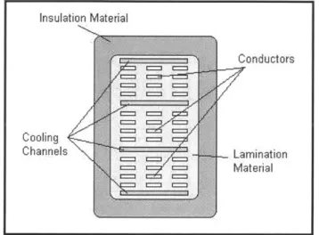
In larger machines, form-wound windings are used for ease of construction and for better performance. A sketch of what a form-wound winding looks like is shown in Figure 14.
Typically, machines contain two coil sides per slot making the winding a double-layer design
[17], [18], [19]. Overall, slot fill factors vary in value from 0.30 - 0.70, depending on the
number and size of the conductors in the slots as well as the amount of labor utilized. In this paper, a slot fill factor of 0.50 is assumed.
Insulation Material
Conductors
Cooling
Channels .Lamination
Material
Figure 14: Example of Form-Wound Winding
In conductors that carry high-frequency currents, skin effect can become an issue and affect the operation of the machine. Skin effect is caused by eddy currents in the windings themselves due to the changing magnetic field. These eddy currents force the current flowing in the conductor to crowd to the outer edges of the conductor. This in turn causes the current to flow through a smaller cross-sectional area and increase the resistance of the conductor. However, the generator under design is expected to operate at less than 2 kHz and for
frequencies below 12 kHz, RACIRDC < 1.01 so skin effect can be neglected [32].
Within a phase, stator windings can be connected in wye or delta patterns as well as series or parallel. Almost all machines use series, wye-connected windings because they provide the safest alternative. This is because in a delta or parallel connection, the back EMFs can produce circulating currents which can result in addition losses, heating, or damage. Therefore, wye series connected windings are selected for use in the designs in this paper.
3.3 Machine Calculated Parameters 3.3.1 Basic Model
Since the machine is assumed to balanced, parameters can be determined on a per-phase basis and then applied to all of the phases. Each phase of the machine can therefore be modeled
as shown in Figure 15.
Ra Ls
Figure 15: Per Phase Model
The armature resistance (Ra) is the resistance of the windings of the machine and it is usually relatively small. The synchronous inductance (L,) of the machine comes from the inductance of the windings and is composed of the air gap inductance, the slot leakage inductance, and the end-turn inductance. The back voltage (Ea) is produced through the flux linkage in the windings
from the rotating magnetic field in the machine. Lastly, Va is the terminal voltage and is found
using basic circuit analysis once the other parameters are known.
3.3.2 Winding Resistances
The stator coils in the machine are made of copper and therefore have some resistance to the current flow. This resistance of the copper phase windings is calculated using Eqn 3-8.
Ra
=aA
where I = length of conductor
a= winding conductivity
A = winding cross-sectional area
Eqn 3-8
The length of the conductor comes from the windings traveling twice the length of the machine and twice around the end turns of the machine. It is assumed that the end turns follow roughly a
circular path from one side of the machine to the other where the radius of the circle is the distance to one half the stator slot height. The cross-sectional area of the conductor is obtained from the slot area and slot fill factor as shown in Eqn 3-9, assuming form-wound windings.
AA
ac -2-Nc
where As = slot area
NC = turns per coil
Eqn 3-9 3.3.3 Winding & Magnet Factors
As discussed in section 3.2.7, windings are normally not full-pitched or concentrated but rather are short-pitched and have breadth associated with them. To account for these effects, a winding factor (kw) is utilized which is the ratio of flux linked by an actual winding to the flux linked by a full-pitch, concentrated winding having the same number of turns. The winding factor is the product of a pitch factor (kp) and a breadth/distribution factor (kb) as shown in Eqn
3-10.
k wn = k kbn
Eqn 3-10
The pitch factor accounts for the windings spanning a electrical degrees vice spanning a full 1800 E as shown in Figure 16 [26].
The pitch factor is the ratio of the flux produced by a short-pitch coil to the flux produced by a full-pitch coil. Short-pitching is an important means for eliminating harmonics and improving the power quality of the machine. The pitch factor can be derived with the final result shown in Eqn 3-11.
kpn = sin ( -a ).sin( nhjr
where n = harmonic number
Eqn 3-11 The breadth factor explains the effect of the windings occupying a distribution or range of slots within a phase belt. A phase winding normally consists of numerous coils connected together linking flux slightly out of phase with each other as shown in Figure 17 [26].
Figure 17: Winding Breadth
The breadth factor can be derived either magnetically or geometrically to obtain Eqn 3-12.
. n-m-y
sC
2kbn = 2
m. sin( n-y
2
where n = harmonic number
m = slots per pole per phase
y = coil electrical angle
Eqn 3-12
In addition to estimating different winding effects, the geometry of the magnetic air gap must be represented. Field methods are utilized along with vector potential analysis to develop expressions that account for different magnetic gap geometries. Reference [19] contains detailed
derivations of the magnetic gap factor (kgn) for several magnet and slot configurations. The equation for the slotted stator, surface magnet configuration is shown in Eqn 3-13.
kgn 2 -2np np+1 .(R2 np+ - RInp+1 np - R 2np( R l-np - R2 -np
Rskn _
w rR
[Cp
/ +1 + I np- Iwhere RS = outer magnetic boundary R2 = outer boundary of magnet
Ri = inner magnetic boundary R1 = inner boundary of magnet
Eqn 3-13
3.3.4 Flux and Voltage
The primary significance of the magnetic flux linkage in a machine is that it induces voltage across a winding whenever the flux varies with time as explained through Faraday's Law. The first step in the process is to determine the air gap flux density. The flux from the magnet poles crosses the air gap to the stator windings but some flux leaks along the way and this is accounted for using a leakage factor (KI ~ 0.95 for surface magnets). In addition, the flux path is normally dominated by the air gap reluctance since the reluctance of the stator steel is
much less than that in the air gap. However, a reluctance factor (Kr - 1.05 for surface magnets)
is used to compensate for the small effects of the steel reluctance on the air gap flux.
The presence of the slots in the stator also affects the air gap flux density because of the difference in permeance caused by the slots. The flux crossing the air gap in a slot region travels farther before reaching the highly permeable stator back iron. Carter's coefficient (Kc) is used to account for this effect [17]. The air gap flux density is also affected by the magnet geometry in the air gap as previously described by Eqn 3-13. Since the magnet poles rotate north/south, the air gap flux density shape can be approximated as shown in Figure 18. This can be represented as a Fourier series using only odd components because of half-wave symmetry as shown in Eqn