HAL Id: insu-01131801
https://hal-insu.archives-ouvertes.fr/insu-01131801
Submitted on 6 Dec 2019HAL is a multi-disciplinary open access archive for the deposit and dissemination of sci-entific research documents, whether they are pub-lished or not. The documents may come from teaching and research institutions in France or abroad, or from public or private research centers.
L’archive ouverte pluridisciplinaire HAL, est destinée au dépôt et à la diffusion de documents scientifiques de niveau recherche, publiés ou non, émanant des établissements d’enseignement et de recherche français ou étrangers, des laboratoires publics ou privés.
Microseismicity Induced in the Opalinus Clay by a
Gallery Excavation in the Mont Terri Underground
Rock Laboratory
Yves Le Gonidec, Christophe Nussbaum, J. Sarout, Jérôme Wassermann, Paul
Bossart
To cite this version:
Yves Le Gonidec, Christophe Nussbaum, J. Sarout, Jérôme Wassermann, Paul Bossart. Microseis-micity Induced in the Opalinus Clay by a Gallery Excavation in the Mont Terri Underground Rock Laboratory. 49th US Rock Mechanics / Geomechanics Symposium, American Rock Mechanics Asso-ciation, Jun 2015, San Francisco, United States. �insu-01131801�
1. INTRODUCTION
A large scale geological rock mass is subjected to different natural stresses, including tensional, compressive and shear stresses. The rock response to stress is controlled by the stress type itself but also to the lithology, the pressure condition the rock is under and the time the rock is under stress. Depending on these in situ conditions, which control the stress field, different damage structures may appear in the geological structure, including faults, fractures, cracks and/or crystal dislocations [1,2].
At short time and space scales, the stress field can be modified for instance when a gallery is excavated in such a stressed environment : it induces a stress redistribution in particular in the vicinity of the excavation, the so-called excavation damaged zone (EDZ) [3,4]. Characterization of the EDZ is of primary
importance in many research topics related to underground galleries, in particular when dealing with deep geological repositories. Indeed, damage structures constitute preferential pathways for radionuclides to reach the free surface or ground water reservoirs. In this context, clay formation are interesting for both its low permeability and its self-sealing capacity [4,5]. As a consequence, monitoring the EDZ in such geological formation is a major but not straightforward research field which motivate numerous in situ experiments in the underground research laboratory (URL) of Mont Terri (Switzerland), situated in the Opalinus Clay formation of the Folded Jura [6,7].
In 2008, the so-called EZ-G08 experiments performed in the Mont Terri URL, aimed at monitoring short time spatio-temporal changes in the vicinity of a new gallery, i.e. both the initiation and extension of an EDZ, by the use of geophysical methods [8-11]. Because excavation
ARMA 15-0478
Microseismicity Induced in the Opalinus Clay by a Gallery Excavation in
the Mont Terri Underground Rock Laboratory
Le Gonidec, Y.
Géosciences Rennes, UMR6118-CNRS, Rennes, France
Nussbaum, C.
Swisstopo, Swiss Geological Survey, Wabern, Switzerland
Sarout, J.
CSIRO, Earth Science and Resource Engineering, Perth, WA, Australia
Wassermann, J.
Mechanics and Materials of Civil Engineering, University of Cergy-Pontoise, France
Bossart, P.
Swisstopo, Swiss Geological Survey, Wabern, Switzerland
Copyright 2015 ARMA, American Rock Mechanics Association
This paper was prepared for presentation at the 49th US Rock Mechanics / Geomechanics Symposium held in San Francisco, CA, USA, 28 June- 1 July 2015.
This paper was selected for presentation at the symposium by an ARMA Technical Program Committee based on a technical and critical review of the paper by a minimum of two technical reviewers. The material, as presented, does not necessarily reflect any position of ARMA, its officers, or members. Electronic reproduction, distribution, or storage of any part of this paper for commercial purposes without the written consent of ARMA is prohibited. Permission to reproduce in print is restricted to an abstract of not more than 200 words; illustrations may not be copied. The abstract must contain conspicuous acknowledgement of where and by whom the paper was presented.
ABSTRACT: In the Clay formation of the Mont Terri, we have performed acoustic experiments to monitor the excavation damaged zone induced in the surrounding of a new gallery Ga08. The experiments took place in the end-face of a previous gallery Ga04 with an excavation operation coming from the opposite direction to joint both galleries. The study dealt with the rock mass segment, 8 m in length, left for two weeks between the Ga04 end-face and the Ga08 excavation front. Acoustic surveys, performed with a controlled acoustic source introduced inside the rock mass segment, allowed defining the transversely isotropic P-wave velocity field of the medium. Passive acoustic measurements, which consisted in detecting induced acoustic events, allowed identifying actual microseismic events induced by stress redistribution in the surrounding of the Ga08 excavation front. We assessed the damage mechanism of these events and clearly highlighted strong correlations between spatial, temporal and mechanism attributes, in agreement with both the geological facies and the gallery orientation with respect to geological pre-existing features. Finally, we present preliminary results on additional acoustic events located inside the rock mass segment.
operations induce stress redistribution, induced acoustic emissions can be expected as signatures of damage zone initiation as reported in many works performed in brittle rocks for instance [12,13]. In soft rocks, such as the Opalinus Clay, only very few results have been published because of the difficulty in detecting acoustic emissions in soft and highly attenuating clay-rich rocks [14,15]. The results presented in this work, contribute to fill this data scarcity: in particular, by performing both active (seismic surveys) and passive (microseismicity) acoustic experiments, we are able to clearly identify few but actual in situ microseismic events (MSEs) induced by gallery excavation [9,11]. More recently, we have studied additional events identified and located inside the rock mass segment. In Section 2, we introduce the large scale rock mass segment where the acoustic experiments took place to monitor the EDZ. The principles and main results of the active seismic survey experiments are presented in Section 3 to define the physical properties of the rock mass segment. Section 4 is dedicated to the passive microseismicity experiments where actual MSEs are identified. In Section 5, we analyze the results in terms of damage mechanism and discuss the spatial distribution of the dominant mechanism component of each MSE. In the last section, we present preliminary results about a similar and complete analysis performed on additional acoustic events identified and located inside the rock mass segment.
2. DESCRIPTION OF THE ROCK MASS
SEGMENT
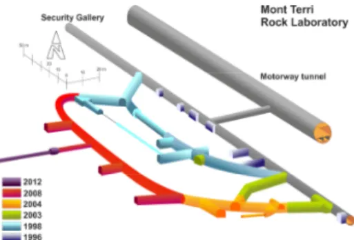
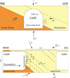
Formed in marine environments of different depths, sedimentary rocks can be folded because of tectonic stresses and uplifted. The geological formation is characterized by bedding plane structures. This is the case of the dome-shaped fold of the Mont Terri anticline, mainly composed of marly claystone with different proportions of sand and carbonate, and characterized by three main tectonic faults, including moderately SSE-dipping reverse faults [16,7]. In the Opalinus Clay formation of the dome, the URL of Mont Terri is located 300 m below the surface (Fig. 1).
Fig. 1. The EZ-G08 experiments took place in 2008 in the Mont Terri URL at the junction between galleries Ga04 (orange) and Ga08 (red).
The EZ-G08 experiments took place in 2008 at the junction between two galleries [9]: an old gallery Ga04 excavated in the shaly facies in 2004, and a new gallery Ga08 which excavation was coming from the opposite direction in the sandy facies (Fig. 1). Because of the different lithologies encountered during the excavation, the excavation progression was 0.5 to 2.5 meters per day and performed with a road header [17] for a smoother excavation of the gallery which diameter is roughly 5 meters. Around July 12, the excavation operations stopped for two weeks when the rock mass segment between Ga08 and Ga04 was 8 meters in length.
In order to monitor the EDZ, the acoustic experimental setup was introduced since July 10 in the surrounding of the excavation front by the use of boreholes drilled in the rock mass segment from the Ga04 end-face: four boreholes (BEZ-G16 to BEZ-G19) were used to insert an array of 16 acoustic sensors which recorded the signals emitted by the controlled active sources located in a central borehole (BEZ-G5) for the acoustic survey measurements, or by induced microseismic events (MSEs) which locations are not known a priori.
3. PHYSICAL PROPERTIES OF THE ROCK
MASS: ACOUSTIC SURVEY MEASUREMENTS
3.1. Principles of the active experiments
The acoustic survey measurements consisted in sounding the rock mass with ultrasonic pulses [9]. To do so, a controlled acoustic source had been designed to be introduced at different depths inside BEZ-G5, between 4.4 to 6.8 m from the end-face of Ga04 in steps of 40 cm, i.e. seven equivalent sources were used. The acoustic frequency of the emitted pulse was around 30 kHz and the waveforms (time length of 4 ms with 2048 points sampled at 500 kHz) recorded at each acoustic sensor resulted from 200 stacks to improve the signal-to-noise ratio. The offset between two sensors of a common borehole being 1 m, the last three meters of the rock mass segment can be sounded along different raypaths relative to the bedding structure of the clay formation. The data processing was performed with the Insite® Seismic Processor Software (ASC Ltd.), used in
a first step to define the P-wave velocity Vp from the
first arrival time picked on each waveform when a controlled source signal is emitted (Fig. 2).
Fig. 2. Acoustic waveforms recorded during a seismic survey (normalized amplitude). The source signal (red) has a central frequency of 30 kHz.
We did not observe any clear variations of Vp during the
time period of the experiments but we highlighted strong variations of Vp as a function of the raypath angle
relative to the bedding planes. The rock mass segment was thus characterized by a transversely isotropic P-wave velocity field, with a maximum value close to 3400 m/s along the bedding planes and minimum value as low as 2700 m/s in the perpendicular direction, which corresponds to an azimuth N310° and a plunge 38°.
3.2. Spatial location of the active measurements
The velocity model informs about the physical properties of the rock mass segment, in accordance with the geological formation. Moreover, if the effect of rock mass heterogeneities can be neglected, we can use the Insite® software to apply the location algorithm with the
transversely isotropic model and perform the spatial location of the controlled acoustic source at different depths inside the borehole BEZ-G5.
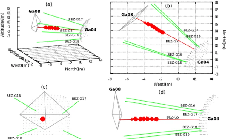
The error-minimization between the measured and modelled travel times is based on the Downhill Simplex Method [18]. We performed the locations of 453 artificial events, which correspond to acoustic survey measurements for different controlled source positions, and the results clearly highlights the seven source positions along BEZ-G5 (Fig. 3).
-8 -6 -4 -2 0 2 4 -2 -1 0 1 2 3 4 5 6 7 8 -3 -2 -1 0 1 2 3 -8 -6 -4 -2 0 2 4 -2 -1 0 1 2 3 4 5 6 7 8 BEZ-G16 BEZ-G17 BEZ-G19 BEZ-G18 BEZ-G16 BEZ-G17 BEZ-G18 BEZ-G16 BEZ-G18 BEZ-G17 BEZ-G19 BEZ-G16 BEZ-G17 BEZ-G19 BEZ-G18 Ga04 Ga04 Ga04 Ga08 Ga08 Ga08 (a) (b) (c) (d) North (m) West (m) West (m) North (m) Altitude (m) BEZ-G5 BEZ-G5 BEZ-G5
Fig. 3. Spatial location of the artificial sources (red crosses) on the axis of BEZ-G5 (red line): (a) a 3D representation, (b) view from top, (c) view from the excavation front of Ga08 and (d) lateral view of the rock mass segment.
The uncertainty on the location is about 20 cm, which is very satisfactory in comparison to the 8 m length of the rock mass segment.
4. INDUCED MICROSEISMICITY AROUND
THE ROCK MASS: PASSIVE ACOUSTIC
EXPERIMENTS
4.1. Principles of the passive experiments
Because of the stress redistribution in the rock mass surrounding when the gallery is excavated, local cohesion losses of the rock can be induced and potentially radiate elastic energy, i.e. microseismic waves [19]. Passive acoustic experiments aim at recording such microseismic events (MSEs). To do so, we used the acoustic array of 16 receivers to record events according to detection criteria based on the event waveforms [9,11]: a fixed amplitude threshold (50 mV) satisfied by a minimum number of channels (4). At the end of the two weeks experiments, more than 56,000 events have been recorded in the raw data set, including noise sources (electronic, electromagnetic), anthropic sources (excavation operations), weak sources (low signal-to-noise ratio) and potential MSEs (strong release of elastic energy). Note that an event waveform is sampled at 500 kHz and has a time length of 4 ms.
4.2. Identification of the MSEs data set
We have developed a multi-criteria filtering algorithm to remove all the electronic noise from the raw data set of recorded events. The main step of the filtering is based on the frequency content of the event waveforms. The acoustic sensors are broadband transducers, with a nearly flat frequency response from 2 Hz up to 60 kHz. We observed no significant acoustic energy at frequencies larger than 20 kHz and the limited waveform time window is not adapted to process signals with frequencies lower than 250 Hz. As a consequence, we band-pass filtered the waveform signals in the audible frequency range: the time distribution of the remaining events was then in good coherence with the time schedule of the excavation operations which actually induced most of these acoustic events. But after the excavation stopped, few events remained and could be associated to actual MSEs: a burst of hundred of MSEs was detected on July 11, and another when the excavation was stopped, i.e. 71 MSEs on July 12 and 16 MSEs on July 13. As an illustration, we display a typical acoustic waveform of a MSE (Fig. 4).
0 1 2 3 4
Time (ms)
Norm. Ampl.
Fig. 4. Typical acoustic waveform of a MSE recorded in the argilite of the Mont Terri URL (normalized amplitude).
4.3. Spatial distribution of the MSEs
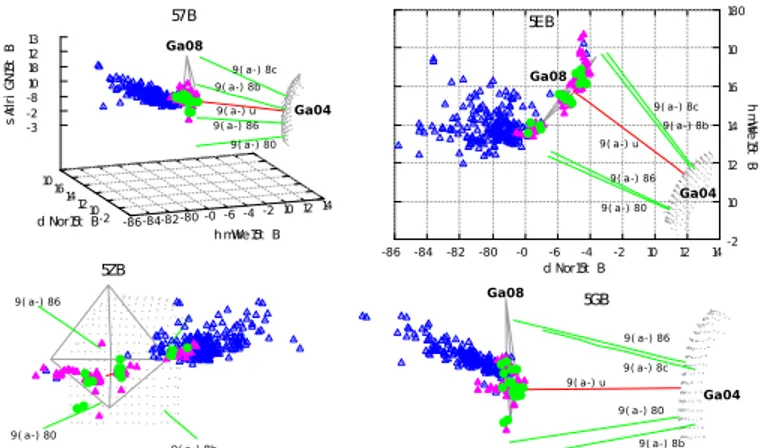
The microseismic events identified on July 11, on the one hand, and on July 12 and 13, on the other hand, are associated to acoustic waveforms with good signal-to-noise ratio. This allows picking the first arrival time required to locate the event in the rock mass surrounding, according to the method performed to locate the controlled acoustic source of the seismic survey measurements (Fig. 3). The location of the MSEs, plotted in Fig. 5, is not random: the results clearly highlight a spatial distribution of the event in the surrounding of the excavation front.
-86-84-82-8 -0-6 -4 -2 1 12 14 -2 1 12 14 16 10 -3 -2 -81 18 12 13 -86 -84 -82 -8 -0 -6 -4 -2 1 12 14-2 1 12 14 16 10 18 57B 5EB 5ZB 5GB 9( a-) 86 9( a-) 80 9( a-) 8b 9( a-) 8b 9( a-) 80 9( a-) 8c 9( a-) 86 Ga04 Ga08 d Nor15t B hm Wre 15t B hmWre15t B d Nor15t B sA rl ri G N 15t B 9( a-) u 9( a-) u 9( a-) u 9( a-) 8c 9( a-) 8b 9( a-) 86 9( a-) 80 Ga08 Ga04 Ga04 Ga08 9( a-) 8c 9( a-) 80 9( a-) 86 9( a-) 8b
Fig. 5. Spatial location of the MSEs detected on July 11 (blue triangles) and July 12 and 13 (pink and green symbols, respectively) - See Fig. 3 for a description of the different views.
Detected on July 11, the first burst of events is located in the right-hand sidewall of the Ga08 gallery, i.e. in the shaly facies formation (Fig. 5, blue). The extension of the cluster is partly due to the advancement of the front at the end of the excavation. The location of the events detected on July 12 (Fig. 5, pink) is identical to the location of the events detected on July 13 (Fig. 5, green), suggesting these MSEs correspond to a similar stress redistribution induced by the excavation. The MSEs locate close to the excavation front and their location is structured in two main clusters: one located ahead the excavation front and the other one in the right-hand shaly sidewall of the excavation front.
5. DAMAGE MECHANISMS: INITIATION,
EXTENSION AND EVOLUTION OF THE EDZ
5.1.
Damage mechanisms
To go further into the MSEs analysis, we assessed the associated damage mechanism, an original analysis when performed with stress-induced events in a clay formation. Indeed, the processing requires good quality waveforms in order to identify the first arrival time, already required to locate the events, but also both the amplitude and polarization of the first movement. This picking could not be performed with the MSEs recorded
on July 11, but only with 50 and 11 MSEs recorded of July 12 and 13, respectively. We used the Insite®
software inversion algorithm, based on a time domain Moment Tensor approach [20]. The results give the damage mechanism of each MSE as a mixture between the three main mechanisms, i.e. the double-couple (DC), the compensated linear vector dipole (CLVD) and the isotropic dilatation (ISO) mechanisms. We identified the dominant mechanism for the 61 MSEs and plot the results in the spatial representations previously used. Note that this representation is not available in the processing software.
5.2. Spatial distribution of the damage mechanisms From the damage mechanism analysis, the dominant mechanisms are DC and CLVD: the results, plotted in Fig. 6, clearly highlight a strong correlation with the spatial distribution of the associated events (Fig. 5, green and pink). -86 -4 -2 - -0 16 10 1 -0 16 10 1 12 14 -3 -0 -8 16 18 10 13 -86 -4 -2 - -0 16 10 1 -0 16 10 1 12 14 186 57BEZ1G9 ( a ) bE1G9 ( a ) bE1G9 ( 57 BEZ 1G9( cd EN Eo r ) 1G 9( Gt ( Gh( Gr ( Gm( Wes -A82
Wes -A84 Wes -A8l
Wes -A8i Wes -A8i Wes -A8l Wes -A82 Wes -A84 Wes -Au Wes -A82 Wes -A8i Wes -Au Wes -A84 Wes -A8l Ga04 Ga08 Ga08 Ga08 Wes -A8i Wes -A8l Wes -Au Wes -A82 Wes -A84 Ga04 Ga04
Fig. 6. Spatial distribution of the damage mechanisms: dominant DC (black disks) and CLVD (black stars) components for the MSEs located ahead the excavation front and in the shaly facies sidewall, respectively - See Fig. 3 for a description of the different views.
As a main result, a dominant DC mechanism characterizes the MSEs located ahead the excavation front (Fig. 6, black disks) while a dominant CLVD mechanism characterizes the MSEs located in the shaly facies sidewall of the Ga08 gallery (Fig. 6, black stars). This highlights the correlation between temporal and spatial attributes of the MSEs, as discussed in the previous section, and damage mechanisms.
In particular, the MSEs detected up to two days after the excavation stopped, i.e. July 12 and 13, correspond to similar stress-redistribution processes, with similar spatial distributions associated to similar dominant damage mechanisms. Ahead the excavation front, the excavation operations released the rock mass surrounding the excavation front where geological features, including bedding and subparallel faults, were free to slip in a dominant DC mechanism as highlighted by the damage mechanism of the related MSEs. Inside the sidewall, the geological features were not free to slip
and we did not observe any dominant DC mechanisms in the related MSEs for which a dominant CLVD component has been highlighted in the present study: these in situ results are in agreement with the subvertical maximum compressive stress of the Mont Terri which induced tensile fractures.
6. ADDITIONAL PRELIMINARY RESULTS
The MSEs identified in Section 4.2 are stress-induced events related to the excavation operation, as highlighted by their spatial location in the surrounding of the excavation front. But among the data set of events identified as potential MSEs, we did not yet consider other events detected few days later when the excavation operation was stopped.
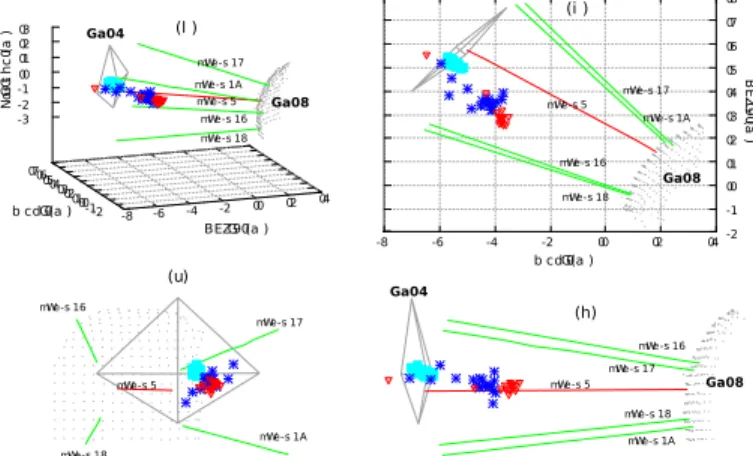
Indeed, on July 14, a borehole drilling was performed in the morning at the Ga08 excavation front. Six hours later, few tens of induced acoustic events could be detected, identified and located according to the approach presented above for the MSE analysis. About 70 acoustic events, which all occurred in less than one minute of time, were located at the excavation front and clustered along the borehole axis, highlighting one more time the efficiency of the experimental approach performed at Mont Terri (Fig. 7, cyan).
-8 -6 -4 -2 0 2 4 -2 -1 0 1 2 3 4 5 6 7 -3 -2 -1 0 1 2 3 -8 -6 -4 -2 0 2 4-2 -1 0 1 2 3 4 5 6 7 8 BE ZG 9 ( a ) b cdG (a ) BEZG9 (a ) b cdG (a ) Ga04 Ga04 No GrG t h c (a ) Ga08 Ga08 Ga08 mWe-s 17 mWe-s 17 mWe-s 17 mWe-s 17 mWe-s 1A mWe-s 1A mWe-s 1A mWe-s 1A mWe-s 18 mWe-s 18 mWe-s 18 mWe-s 18 mWe-s 16 mWe-s 16 mWe-s 16 mWe-s 16 mWe-s 5 mWe-s 5 mWe-s 5 mWe-s 5 (l ) (i ) (h) (u)
Fig. 7. Spatial location of the acoustic events detected on July 14, induced by a borehole drilling (cyan symbols) followed by two cluster of events (blue and red, respectively) - See Fig. 3 for a description of the different views.
The borehole drilled on July 14 was used for resin injection and few hours later, we identified two bursts of acoustic events located inside the rock mass segment: cluster 1 is composed of nearly 20 events and locates on the left-hand side of the rock mass (Fig. 7, blue) followed fifteen minutes later by cluster 2 which locates in a close but separate part of the rock mass (Fig. 7, red). As a first attempt, we assessed the damage mechanisms of these events, as implemented in the Insite® software
which plots the results in the Hudson T-k plot [21]
(Fig. 8).
Fig. 8. Hudson T-k plot of acoustic events located inside the rock mass segment (see Fig. 5).
In such T-k plot, T- and k-axes represent the shear and volumetric portion of the mechanism, respectively. For instance, a DC mechanism is defined by (T,k)=(0,0) and a CLVD mechanism by (T,k)=(+1,0). The results of the analysis, based on few events associated to weak amplitude waveforms, clearly show that the distribution of the damage mechanism is not random: two clusters can be observed, characterized by a dominant DC mechanism for the first burst of events cluster 1 (Fig. 7, blue) and a dominant CLVD mechanism for cluster 2 (Fig. 7, red).
This study requires further analysis but already highlights a clear correlation between spatial, temporal and mechanism attributes of the acoustic events, as we discussed above for the MSEs induced by the excavation of a new gallery.
7. DISCUSSION AND CONCLUSION
When a new gallery is being excavated, stress redistribution occurs around the excavation and elastic energy should be released by induced cracks, i.e. microseismic activity. In soft rocks, such as shale formation like the Opalinus clay (OPA), this amount of energy is very weak and thus difficult to detect. As a consequence, very few microseismic studies have been published for clay-rich rocks, in particular at the field scale. The present work contributes to fill this data scarcity, through the EZ-G08 acoustic experiments performed in a rock mass segment of the Opalinus Clay formation of the Mont Terri URL.
The transversely isotropic distribution of the P-wave velocity of the rock mass segment was determined by the use of active acoustic survey measurements. The results did not clearly show temporal variations of the velocity field during the two weeks of the experiment and allowed an efficient spatial location of the involved active sources. During the experiments, many thousands of events were recorded: most of them were electronic noise and anthropic events induced by the gallery excavation and only few hundreds microseismic events (MSEs) could be identified by the use of a multi-step
filtering method. A first burst of events was located on the shaly facies of the sidewall of the excavated gallery and no event occurred in the sandy facies which crack initiation threshold is higher, i.e. the lithology clearly controls the microseismic activity [15]. A second cluster of MSEs located in the vicinity of the excavation front and could be divided in two sub-clusters. The first one occurred ahead the excavation front and corresponded to a dominant double-couple (DC) source mechanism: this suggests a shear process induced by the bedding plane reworking because the excavation released the constraints at the front where the bedding and subparallel faults were free to slip. The second one occurred in the shaly facies sidewall of the excavated gallery and were associated to a dominant compensated linear vector dipole (CLVD) component associated to an axial splitting process where a spalling damage could be initiated. Actually, in the sidewall, the pre-existing geological structures were not free to slip and because of the vertical major principal stress axis, tensile fracturing occurred.
Fig. 9. Conceptual representation of the stress pattern around the excavated gallery.
As a conclusion, the present work performed in a clay-rich rock mass segment highlights results consistent with previously published works in brittle rocks. In particular, the stress redistribution induced by the excavation in the gallery surrounding shows a correlation between three main attributes of the induced microseismicity, including spatial, temporal and source mechanism attributes (Fig. 9). More recently, additional microseismic events had been identified and located inside the rock mass segment. These new results highlight the efficiency of the EZ-G08 acoustic experiments in detecting induced MSEs in the Opalinus Clay: the origin of these events may be in relation with resin injection but still constitutes a forthcoming study.
ACKNOWLEDGMENTS
The EZ-G08 experiments were funded by CNRS and ANDRA through the GNR FORPRO II. The authors would like to thank A. Schubnel (ENS Paris), D. Gibert and B. Kergosien (Géosciences Rennes), A. Maineult (METIS) and the staff of Mont Terri URL (T. Theurillat, C. Girardin, V. Risse and G. Joliat) for their contributions to the field experiments. The Insite®
software was first lended by A. Schubnel (ENS Paris) and then by D. Dewhurst (CSIRO, Perth).
REFERENCES
1. Weiss, J. 2003. Scaling of fracture and faulting of ice on Earth. Surveys in Geophysics 24: 185-227.
2. Lemaitre, J. 1990. Micro-mechanics of crack initiation. International journal of fracture 42: 87-99.
3. Martino, J. B. and N.A. Chandler. 2004. Excavation-induced damage studies at the underground research laboratory. International Journal of Rock Mechanics and Mining Sciences 41: 1413-1426.
4. Blümling, P., F. Bernier, P. Lebon, and C.D. Martin. 2007. The excavation damaged zone in clay formations time-dependent behaviour and influence on performance assessment. Physics and Chemistry of the Earth, Parts A/B/C 32: 588-599.
5. Bastiaens, W., F. Bernier, and X.L. Li. 2007. SELFRAC: Experiments and conclusions on fracturing, self-healing and self-sealing processes in clays. Physics and Chemistry of the Earth, Parts A/B/C 32: 600-615. 6. Bossart, P., P.M. Meier, A. Moeri, T. Trick, and
J.C. Mayor. 2002. Geological and hydraulic characterisation of the excavation disturbed zone in the Opalinus Clay of the Mont Terri Rock Laboratory. Engineering Geology 66: 19-38.
7. Nussbaum, C., P. Bossart, F. Amann, and C. Aubourg. 2011. Analysis of tectonic structures and excavation induced fractures in the Opalinus Clay, Mont Terri underground rock laboratory (Switzerland). Swiss Journal of Geosciences 104: 187-210.
8. Nicollin, F., D. Gibert, N. Lesparre, and C. Nussbaum. 2010. Anisotropy of electrical conductivity of the excavation damaged zone in the Mont Terri Underground Rock Laboratory. Geophysical Journal International 181: 303-320.
9. Le Gonidec, Y., A. Schubnel, J. Wassermann, D. Gibert, C. Nussbaum, B. Kergosien, J. Sarout, A. Maineult, and Y. Guéguen. 2012. Field-scale acoustic investigation of a damaged anisotropic shale during a gallery excavation. Int. J. Rock Mech. Min. Sci. 51: 136–148.
10. Maineult, A., B. Thomas, C. Nussbaum, K. Wieczorek, D. Gibert, B. Lavielle, and N. Lesparre. 2013. Anomalies of noble gases and self-potential associated with fractures and fluid dynamics in a horizontal
borehole, Mont Terri Underground Rock Laboratory. Engineering Geology 156: 46-57.
11. Le Gonidec, Y., J. Sarout, J. Wassermann, and C. Nussbaum. 2012. Damage initiation and propagation assessed from stress-induced microseismic events during a mine-by test in the Opalinus Clay. Geophysical Journal International 198: 126–139. 12. Schubnel, A., O. Nishizawa, K. Masuda, X.J. Lei,
Z. Xue, and Y. Guéguen. 2003. Velocity measurements and crack density determination during wet triaxial experiments on Oshima and Toki granites. In Thermo-Hydro-Mechanical Coupling in Fractured Rock (pp. 869-887). Birkhäuser Basel.
13. Lockner, D. A., J.D. Byerlee, V. Kuksenko, A. Ponomarev, and A. Sidorin. 1991. Quasi-static fault growth and shear fracture energy in granite. Nature 350: 39-42.
14. Sarout, J., A. Ougier-Simonin, Y. Guéguen, and A. Schubnel. 2010. Active and passive seismic monitoring of shales under triaxial stress conditions in the laboratory. In EAGE Shale Workshop.
15. Amann, F., P. Kaiser, and E.A. Button. 2012. Experimental study of brittle behavior of clay shale in rapid triaxial compression. Rock Mechanics and Rock Engineering 45: 21-33.
16. Thury, M. and P. Bossart. 1999. The Mont Terri rock laboratory, a new international research project in a Mesozoic shale formation, in Switzerland. Engineering Geology 52: 347-359.
17. Bossart, P., T. Trick, P.M. Meier, and J.C. Mayor. 2004. Structural and hydrogeological characterisation of the excavation-disturbed zone in the Opalinus Clay (Mont Terri Project, Switzerland). Applied clay science 26: 429-448.
18. Nedler, J., and R. Mead. 1965. A simplex method for function minimisation. Comput. J. 7: 308-312.
19. Martin, C. D. 1997. Seventeenth Canadian geotechnical colloquium: the effect of cohesion loss and stress path on brittle rock strength. Canadian Geotechnical Journal 34: 698-725.
20. Young, RP., J.F. Hazzard, and W.S. Pettitt. 2000. Seismic and micromechanical studies of rock fracture. Geophys. Res. Lett. 27: 1767-1770.
21. Hudson, J.A., R.G. Pearce, and R.M. Rogers. 1989. Source type plot for inversion of the moment tensor. J. Geophys. Res. 91: 765-774.