Development of an In-Line Putter for
Handicap Friendly Tabletop Golf Games
By
Sam J. Berberian
SUBMITTED TO THE DEPARTMENT OF MECHANICAL ENGINEERING IN PARTIAL FULFILLMENT OF THE REQUIREMENTS FOR THE DEGREE OF
BACHELOR OF SCIENCE AT THE
MASSACHUSETTS INSTITUTE OF TECHNOLOGY MAY 2007
© 2007 Sam Berberian. All Rights Reserved.
The author hereby grants to MIT permission to reproduce
and to distribute publicly paper and electronic
copies of this thesis document in whole or in part
in any medium now known or hereafter created.
Signature of Author....;; ...
Department of Mechanical Engineering
May 1, 2007
Certified by, ...
.• .• . .. ..
w... .w
....
...
Sang-Gook Kim
Professor of Mechanical Engineering
Thsis Supervisor
Accepted by... .
...
...
John H. Lienhard V
Pro essor of Mechanical Engineering
mASACHUSETTS MIs,,U.
Chairman, Undergraduate Thesis Committee
OF TECHNOLOGY
E0F''=UEC=N=
0G8'Gy
ii
-IjUI'b . ~Handicap Friendly Tabletop Golf Games
by
Sam Berberian
Submitted to the Department of Mechanical Engineering
on May 1, 2007 in partial fulfillment of the
requirements for the degree of Bachelor of Science in
Mechanical Engineering
Abstract
The market for handicapped tabletop games is severely untapped. The students of
the Red Team in the course 2.009 (Product Engineering Processes, a capstone design
project course in the Mechanical Engineering Department) at the Massachusetts Institute of
Technology attempted to produce a tabletop golf game that would even the playing field
between handicapped and able-bodied individuals. This game, Microgolf, was not received
well by the faculty. One of the largest downfalls of Microgolfwas an inherent lack of
control over the putting aspect of the game.
The putter designed by the 2.009 Red Team was difficult to use as it shot the ball
perpendicular to the line of sight path between the ball and the hole used by the user to aim.
The goal of this thesis is to design a user friendly putter that would provide a substantial
amount of control over the shooting aspects of the game, thus truly leveling the playing
field between handicapped and able-bodied individuals, and providing a more exciting
playing environment.
After several rounds of modeling and optimization, a final design is accomplished
that accommodates all of the functional requirements desired by players. This putter is
lightweight and could be used with one hand, aided by a set of legs near the front end that
allowed it to rest on the table for support. The putter relies on user input for aim, and the
ball could be shot in situ after aiming, without having to shift position. A four bar linkage
system and trigger are used to actuate a putter shaft and head such that the output response
is a function of the input force controlled by the finger movement. This shooting action is
repeatable, thus allowing for easy, continuous play while requiring players' delicate control
of orientation and force. The putter itself is visually appealing, and costs less than $5 to
make. This putter is well received by a group of handicapped individuals who are asked to
test it out and provide feedback. This new design would greatly enhance a tabletop golf
game by providing a lot of control over the shooting aspects of the game.
Thesis supervisor: Sang-Gook Kim
Table of Contents
Table of Contents ... 3 List of Figures...4 List of Tables ... 5 Glossary of Symbols... 6 Chapter 1: Introduction...7 Chapter 2: Design...16 2.1 Functional requirements ... .. ... 16 2.2 Design parameters ... 18 2.3 Putter design... ... 19 2.3.1 Putter head... 19 2.3.2 Orthogonality... 202.3.3 Transfer of linear momentum from putter head to ball...21
2.3.4 Peripheral Weighting... 23
2.3.5 Vertical lever rod ... 24
2.3.6 Center of mass calculations for swinging putter ... 27
2.3.7 Putter Enclosure... ... .... 29
2.3.8 Putter legs...30
2.3.9 Aiming ... ... 34
2.4 Linkage design ... 34
2.4.1 Input-output motion interface... 34
2.4.2 Trigger placement ... 35
2.4.3 Rod Linkage material... ... ... 37
2.4.4 Degrees of Freedom ... ... ... 37
2.4.5 Grashof Criteria ... 38
2.4.6 Force Relationships... . ... ... .. 38
2.4.7 Assembly... 40
2.4.8 Friction issues with putter rod linkages... 41
2.4.9 Spring assistance...44
2.4.10 Lowering center of mass for putter enclosure...46
2.4.11 Enhanced aiming ... 47
2.5 Handle and grip design... 48
2.5.1 Limited dexterity putter handle...48
2.5.2 Putter grip... ... 48
Chapter 3: Fabrication and Evaluation... ... 50
Chapter 4: Conclusion...55
List of Figures
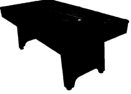
Figure 1.1: Standard pool table Figure 1.2: Foosball table
Figure 1.3: Microgolf table (courtesy of Red Team, 2.009, MIT, 2006) Figure 1.4: A player taking a shot in Microgolf
Figure 1.5: The Kool Pool table
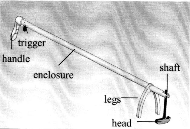
Figure 2.1: Diagram of parts of the putter designed
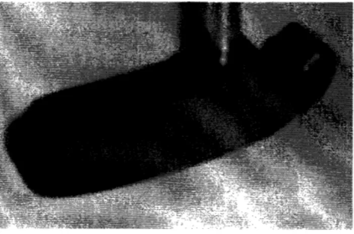
Figure 2.2: Putter head from first prototype shown to be water jetted out of brass stock Figure 2.3: Maximum permissible angular deflection
Figure 2.4: Exhibit of potential moment generation from off center of mass impacts Figure 2.5: Before and after comparison of system's linear momentum
Figure 2.6: Cross sectional view of peripherally weighted putter head with Al core Figure 2.7: Putter shaft allows putter head to swing as a pendulum from pivot point Figure 2.8: Fracture in wall of milled section of putter shaft
Figure 2.9: Optimized putter shaft
Figure 2.10: Force diagram of putter and vertical rod apparatus Figure 2.11: Putter enclosure made of aluminum stock
Figure 2.12: Placement of putter legs 3.5" back from the end of the enclosure Figure 2.13: Putter legs shown to block the users view to a degree
Figure 2.14: Bottom of putter legs in first prototype shown to have semicircular wedges Figure 2.15: Optimized design for putter legs
Figure 2.16: User can clearly see putter head and ball through legs
Figure 2.17: Placement of trigger with respect to handle and putter enclosure Figure 2.18: Example of trigger jamming due to insufficient tolerance
Figure 2.19: Diagram highlighting links in bar linkage
Figure 2.20: Diagram showing key forces and dimensions in 4-bar linkage Figure 2.21: Type 420 Stainless Steel Spring Pins
Figure 2.22: View of inner rod rubbing up against enclosure near trigger Figure 2.23: Assistance from linear spring
Figure 2.24: Cleared up version of linear spring/putter system Figure 2.25: Comfort grip adjustable handle
Figure 2.26: Putter grip
List of Tables
Table 1.1: Comparison of Micro-golf with its competitors: pool and foosball
Glossary
Lower Case Symbols
d -- the vertical distance between pins in the apparatus fi -- total number of joints in a bar linkage
g -- gravitational constant
k -- spring constant
m - mass
n -- number of degrees of freedom
p -- linear momentum t -- time
v -- velocity
y -- length of linear spring
Capital Symbols
F - force
L -- the horizontal distance between the trigger and putter shaft
Greek Symbols
p - density 0 -- angle
Chapter 1: Introduction
During the Fall 2006 Semester at The Massachusetts Institute of Technology, one team of students in the course 2.009 Product Engineering Processes set out with the goal of designing a handicap friendly game. The Red Team (Atiya Hasan, Brad Schiller, Devin Neal, Heather Felix, Mike Beltran, Allan Reyes, Chris Ruggiero, Sam Berberian, Ryan Bavetta, Chris Bateman, Christi Winiarz, Darren Chun, Matt Blanco, Teri Hall, Aron Zingman), one of seven teams in the course, began their work by researching what types of handicap friendly games were already present in the market. They found that many handicap people partake in games such as pool and foosball with great difficulty, yet no game exists that completely levels the playing field between handicapped and able-bodied individuals. The Red Team produced Microgolf, a tabletop golf game. This game was not received well by the faculty, mainly because of a lack of control over the
shooting aspects of the putter. The central goal of this thesis is to provide a user-friendly putter design that will substantially improve control over shooting in the game.
There is a very large market for handicap-friendly games that currently has not been penetrated. This market is mainly composed of United States Community Centers, as these locations have public areas where both handicap and able-bodied people are able to play games. There are currently 10,000 Community Centers in the United States, and with a 10% penetration of this market, a game designer could potentially access a
$5,000,000 market.
The two most popular tabletop games are pool and foosball. These games were designed for able-bodied people, and physically handicapped individuals, especially wheelchair riders, have a great deal of trouble playing. The game of pool is very difficult
to play from a seated position since you need to lever yourself above the table in order to line up your shots comfortably. Also, the aiming and shooting aspects of game play are coupled, which is very difficult for disabled people. They need to line up the pool stick after aiming, and simultaneously shoot without budging. Shooting in pool requires that the user manipulate the pool stick with both hands, which is difficult for users who have limited dexterity or a severe handicap in one hand. It would be optimal to design a game that can be played with one hand, and can be used by individuals who have limited dexterity. Pool is a turn-based game, making it advantageous for users who need extra time to set up their shots. Thus, turn-based games are desirable for handicapped individuals.
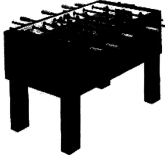
Foosball also cannot be played effectively in a wheelchair since the player cannot get a good view of the tabletop surface from a seated position. The rods that are to be twisted to shoot the ball are positioned so that the player can do so easily from a standing position, but it is tedious from the angle that the player's arm is at when seated. Foosball can be played with one hand, though the player will inherently be at a disadvantage since he/she can only control one line of players while the opponent, if able bodied, would be able to control two simultaneously. Foosball is especially difficult for handicapped individuals since it is not turn based, and both players simultaneously shoot after the ball. Many disabled individuals will not be able to react fast enough and will be at a severe disadvantage when playing against non-disabled players.
Figure 1.2: Foosball table
It is possible to play these two games with a handicap, but it is very difficult and in most cases you will be at a disadvantage if playing against an able bodied person. An
attractive game that levels the playing field between handicapped and able-bodied individuals really has the potential to make an impact. Several nursing homes and community centers around the country were inquired about how well pool and foosball stacked up as games for the handicapped. Most expressed dissatisfaction with pool and foosball tables since their handicapped members would either not play at all, or play and get sick of it immediately because they had a disadvantage to start off with.
Currently, there are no tabletop games that have been able to successfully attract handicap players and level the playing field between these players and able-bodied individuals. For this reason, the 2.009 Red Team created Microgolf, a tabletop golf game.
Figure 1.3: Microgolf table (courtesy of Red Team, 2.009, MIT, 2006)
The goal of this game was to level the playing field between wheelchair riders and standing players to provide fun and excitement for all. The game featured an eight by
four foot table, with a lima bean shaped playing surface. On each of the four corners of the table sat a dial which a player would spin in order to determine which hole he/she was to shoot for. There were four potential outcomes of a spin, "A," "B," "C," and "D," corresponding to the four holes on the table. The game was to be played in an alternating fashion, so after player one shoots at the hole, player two will follow with his own ball, shooting after his own hole, regardless of whether player one made the shot.
As soon as a shot is made, a player can eject the ball using the ball return system that can be activated by pressing one of the four buttons that are on each corner of the table. This places the ball onto the tabletop surface a few inches away from the hole, ready to resume play. This feature was specifically implemented to eliminate the user interface of having to reach over the table and manually retrieve the ball from the hole; something the students imagined would be difficult for wheelchair riders.
The game was made with a degree of variability in order to keep the player engaged. There were 10 different courses for the user to play on within this one table. The first course featured a completely flat tabletop surface, where all the hills were in the down position. After a player made a shot and activated the ball return system, they were to press another button that activated the variable terrain feature. There were several hills built into the table through a piston-cam interface that altered the terrain after each time a player made a shot, thus providing a new course to play on. The players would continue in this alternating fashion until a player became the first to sink 10 shots, thus winning the game.
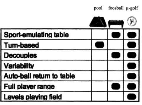
The table below highlights the differences between a well-executed version of
Table 1.1: Comparison of Micro-golf with its competitors: pool and foosball
pool foosball p-golf
Sport-~emulatin table
Tum4beaed
Decouples
Vadablitv
Aub4ll retm t
table
Full leawr ranae
Levels avir field
U1.c
U
il
UIO
U
U
Ull
Ul
UQ~
Still, this product was not received as the most successfully designed product by the 2.009 reviewers, and one of the main reasons was a lack of control over the putter.
Micro-golf featured putters which would rest on the table, enabling the user to twist one
end with his/her hand, causing a rotation of the putter head. This action would be replicated each time the player wished to strike the ball.
Figure 1.4: A player taking a shot in Microgolf
There was difficulty associated with aiming since the ball is struck perpendicular to the line of sight path along the axis of the putter enclosure. In golf, and golf like games, it is best to aim by lining up the ball with the hole so that there is a line of sight path that connects the two. After this is done, in tabletop golf games such as Micro-golf, the user must reposition such that he/she has the putter perpendicular to this line as shown in the picture above. This made shooting inconvenient, since its very hard to determine what is exactly perpendicular after you aim, and you generally have to maneuver around the table to obtain the perpendicular alignment.
After studying the well-received game Kool Pool (designed by the 2.009 Red Team in 2002) that was made in the same course at MIT, it was evident that control is one of the key assets to a well-made game.
Figure 1.5: The Kool Pool table
Kool Pool featured cues that completely decoupled the aiming and shooting components
of pool, permitting a line of sight strike immediately after aiming. The main difference between this game and Micro-golfwas the amount of control the player had over the destination of the ball shot. Creating a putter that would permit a line of sight shot and in the same manner decouple aiming and shooting would result in substantially improved user control in tabletop golf games such as Micro-golf
With the correct implementation of the putter design, Micro-golfwould have great potential. I spoke with many wheelchair rides of varying handicap level, all of which felt an improved version of this game would be something that could hold their interest. Many of these individuals where completely satisfied with the version of the game made by the 2.009 Red Team. Others expressed dissatisfaction with the lack of control.
Several people said they could see themselves playing this game in a bar or community center and having a lot of fun if the putting issues in the game were improved through an enhanced putter design.
The game became less appealing due to an inherent lack of control. The goal of this thesis is to produce a putter that will enable superior control and can be used with any tabletop golf game.
Chapter 2: Design
The principles of axiomatic design provide a systematic approach for a good design. This structured procedure will ensure that we are able to produce the optimal design for this putter without missing any important concepts. We must begin by determining the customer needs for this project. Then, we must determine exactly what we want to do with our design: the functional requirements. Next, we examine all the possible ways we can achieve our goals, coming up with design parameters that correspond to our functional requirements. It is advantageous to go about the design process such that the number of functional requirements equals the number of design parameters; this is known as ideal design [Suh 2001].
There are several requirements to consider in order to create a compact and robust putter which provides superior control over the game and can easily be used by the handicapped. These functional requirements are listed below:
2.1: Functional Requirements & Constraints
1) Can be used with one hand
2) Light weight
3) Can rest on table for support 4) Rely on user input to aim
5) Shoot the ball immediately after aiming by line of sight without shifting position 6) Respond to user input of force control
7) Full follow through on shot 8) Repeatable action
9) Visually appealing
In a table-top golf game such as Micro-golf, the user will need to be able to perform all of the desired functions of the putter with one hand. This is important since wheel chair users may have trouble accessing the table if they have to reach with both
hands. Many handicapped individuals are severely disabled in one hand, leaving them with only one functional hand. Wheelchair riders will prefer to hold the putter in one hand while they maneuver around the table. Since they are to lift the putter and move it around with the strength of one arm, and many of these individuals have limited strength to begin with, the putter should be as light as possible. It will also be necessary to rest one end of the putter on the table for support while moving it around the table by hand at the other end.
The ]putter must rely on user input to aim, in order to provide an element of challenge and differentiation between players of varying skill level. As mentioned earlier, in an effort to decouple the aiming and shooting aspects of game play as done with Kool Pool [Kool Pool 8], the user must be able to shoot the ball in situ after aiming by line of sight without shifting position. The putter design must also respond to the user
input of force to allow for harder and softer shots depending on the ball's initial distance from the hole. The putter needs to be designed such that there is a strong follow through on shots taken. This is important because the rest of the putter should remain fixed in place while the head swings and strikes the ball in order to ensure accuracy. The actions required of the user to take shots must also be easily repeatable to make for easy game play.
The putter must be robust, thus able to take impacts such as being dropped or hitting the table without breaking. The putter must also be visually appealing since this is an important quality for making the overall game attractive. The putter must cost less than $50 to rnake in an effort to keep the price of the overall game package reasonable.
The goal is to find the optimal design that accomplishes each of the above functional requirements. Below are the final design parameters which correspond to the function requirements mentioned earlier.
2.2: Desig•n Parameters
1) Handle and method of triggering putter head within 3 inches 2) Rod made of aluminum (p - 2.7 g/cc) or light-weight composite
3) Attach legs 3.5 inches from the end where putter head is 4) Aim by shifting angle of rod
5) Putter head in line, so that it strikes the ball along the same axis as the putter rod
6) Actuated motion of putter head directly linked with trigger
7) Putter head made of brass (p - 8.5 g/cc)
8) Putter head and bar linkages must return to default position with ease due to weighting
and center of mass position below pivot.
9) Color details: Brass colored handle and bushing. Aluminum rod, legs, and putter arm, black grip(s) and handle. All buffed to provide nice finish after assembly.
2.3: Putter design
2.3.1: Putter head
The putter head itself is a very important component of this design. The putter head should have enough inertia so that it can provide a solid follow through on each shot while the inertia is small enough so that a finger can trigger it. The goal is to essentially transfer the momentum of the swinging putter head to the ball. Using a putter head without enough inertia may result in an inefficient transfer where the front end of the putter apparatus recoils and the legs shift in position. This would result in a less accurate shot since the putter will likely be striking the ball at an angle that is slightly different than intended.
The putter head is to be water jetted out of brass stock. The stock is ultra-machinable brass (Allow 360) with a yield strength of 20,000psi and a /2 Hard (H02) Temper. The putter head was designed to emulate mini-golf club heads. Standard golf putter heads are simply too massive for a game of this scale.
2.3.2: Orthogonality
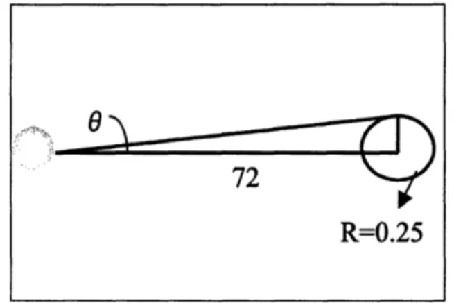
The putter head must be designed so that it has adequate inertia along the axis of the swing direction to prevent it from shifting from its fixed angle with the vertical rod that it is attached to. It is important to define a maximum angular deflection when designing a device such as this. The diameter of the holes in the game Micro-golfis 2.5". The table surface itself is 4 feet by 8 feet. The maximum permissible angular deflection is calculated by determining how much deflection can be allowed on the furthest possible shot without causing a shot that would have originally gone into the hole to miss. The longest shot in this game was 6 feet. The maximum deflection that will be accepted in this design is one that causes the ball to end up half a hole diameter (1.25") away from where it would have. This angle can be solved for by examining a simple triangle with height 1.25" and base 72". The maximum permissible deflection is calculated below.
Figure 2.3: Maximum permissible angular deflection 72
O = tan- ( ) = lo (6)
72
If the inertia along the swing axis is not enough to maintain the position of the
putter head :relative to the shaft, the head will rotate. One way to eliminate the possibility of this occurring is to insert the shaft at the center of mass of the putter head. This will minimize any moments that are generated as a result of striking the ball with the center of the putter head.
Figure 2.4: Exhibit of potential moment generation from off center of mass impacts
It has been determined that there is adequate inertia along the swing axis to prevent off center shots. The design shown on the left of the above figure, and in Figure 2.2, has been determined to be superior as it is more pleasing to the eye, and does not have non-negligible impacts on performance.
2.3.3: Transfer of linear momentum from putter head to ball
The interaction between the putter head and the ball will determine how far the ball will go, as well as in what direction. The relationship between the speed of the club head and the initial velocity of the ball depends on the coefficient of restitution of the
4
4-ball, which varies between different types of balls. When the ball is struck, it is deformed and flattened by the force of impact. A harder ball will in general travel farther than a softer ball because it deforms less and will efficiently transfer more energy from club to ball. During the impact between the ball and club head, kinetic energy is transferred and stored as the ball tries to regain its original shape. In the case of putting, deformation of the ball is negligible, so the ball is thought of as a rigid body.
To determine the mass and properties of the putter head, it is important to
consider the transfer of linear momentum between the swinging putter head and the ball. The putter head can be modeled as a pendulum, and it is safe to assume that it will strike the ball when it is at the bottom of its arc, with its entire velocity in the horizontal component.
Figure 2.5: Before and after comparison of system's linear momentum
The calculations for the conservation of linear momentum in this system appear below: mp'vp' mpVp
mb'Vb
I .•"~ I ;r"Pinitial = Pfina (7) mbvb + mpvp = mbvb+mpvP (8) vb =0 (9) : m " P - mbvb v (10)
1P
(vp -- v,')The mass of a golf ball is approximately 0.046 kg [Glenn 1]. After building a mockup of this putter and performing several tests, I have determined that the head would take an average of 0.15 seconds to swing through its full amplitude when triggered by a user at close to full force. The amplitude of the motion is 3.5", meaning that the average velocity of the putter head is 0.6m/s. This figure is an upper limit, and we will consider upper limits for all of our variables here in calculating the appropriate putter head mass. After several tests of hitting golf balls on a table, it has been determined that the upper limit on the desired velocity of the ball is about 0.75m/s. Assuming that linear
momentum :is conserved in the collision between the putter head and the ball, and that all energy loss due to heat and sound are negligible, the required mass of the putter head is 0.084kg.
2.3.4: Peripheral Weighting
In designing the putter head, it is also important to consider the concept of peripheral weighting. When putting, it may be difficult to always hit the ball in the middle of the putter head, and even a shot that is a little off center may result in a slight angular deviation. If the weight of the putter head is distributed as far from the central axis as possible, the effects of off-center impacts will be reduced by a great deal. This
will result in an enlarged "sweet spot" on the putter face [Riches 2]. After calculating the desired mass of the putter head above, the geometry of the putter head can be designed to achieve this mass, given the density of brass, with a mass distribution where the central section of the putter head is hollow. This will clearly enlarge the outer volume of the putter head. Another alternative is to remove brass near the ends and insert a material with a substantially higher density. A third alternative would be to hollow out the central section of the putter and insert a material with a density much less than brass, such as aluminum or a hard polymer such as epoxy.
brass nminum
Figure 2.6: Cross sectional view of peripherally weighted putter head with aluminum core
2.3.5: Vertical lever rod
The putter head will be press fitted onto the vertical shaft. The putter shaft is the means of attaching the putter head and allowing it to swing as a pendulum.
Figure 2.7: Putter shaft allows putter head to swing as a pendulum from a point where it is pivoted at the putter enclosure
This rod does not need to be made of a dense material, as long as it can take the impact of putting without deforming. It will be made of aluminum stock, so that the overall putter can be as light as possible. This piece was originally made in the first prototype with a tapered design where the lower four inches have a 0.25" diameter. The top two inches had a standard 0.5" diameter, and there was a tapered diameter in the
intermediate 2" running from 0.5" diameter to 0.25" diameter. This piece was made on a lathe from 0.5" stock Multipurpose Aluminum (Alloy 6061). The 0.25" section was made with a standard cut. The tapered region was made with an angled cut. The cut required the lathe to feed inward 0.125" over a length of two inches. The angle to be used can simply be calculated as follows:
0 = tan-'( ) = 3.570
2 (11)
Once this was done, a section was milled out of the 0.25" diameter region. This is where the rod that connects the trigger to the shaft was inserted and attached. A
problem came up when this machining was performed. The rod remained in tact after the section was milled out. The thickness of the walls on either side of the milling was only
1/16". One of the walls fractured when the spring pins were being inserted during the final assembly.
Figure 2.8: Fracture in wall of milled section of putter shaft
After the first prototype was built, the design of this shaft was optimized based on lessons learned. The diameter of the shaft will be 0.375" so that the walls of this milled section will be thicker. The top of the putter shaft consisting of a tapered diameter and a larger diameter (section which acted as a counterweight) were removed. A section at the
putter shaft of length 0.5" will remain of diameter 0.25" to allow for a press fit into the putter head.
Figure 2.9: Optimized putter shaft
The hole placement in the putter enclosure and the putter shaft was carefully calculated so that the bottom of the putter head is able to rest with a tolerance of 0.1" off the ground when assembled.
2.3.6: Center of mass calculations for swinging putter
The putter and putter shaft combination will have to be weighted so that the center of mass of the putter/shaft combination is below the pivot point. If the putter and putter shaft combination are pivoted with the center of mass higher than the pivot point, the system will not return to its default vertical position after each shot.
Figure 2.10: Force diagram of putter and vertical rod apparatus
A force and moment balance is to be done on the system shown above to
determine some key relationships. In equilibrium, the sum of the forces in the x (horizontal) and y (vertical) direction must be zero. Applying this force balance to the above figure yields:
IF, =0 (12)
.' Fx = 0 (13)
F, = F, - mg = 0 (14)
.' FN = mg (15)
Now we must sum the moments. For convention, the moments will be summed along the z-axis (positive out of the page, negative in). The moments will be considered at the pivot point shown above, which will be referred to as point A.
I Arz = -mgx (16) sin() = x /d (17)
FN
vot Point
Center of mass
x
FG=mg
x = dsin(0)
.A z-Z-mgdsin(O) = (19)
The above expression represents the restoring torque exerted on the putter after a shot has been taken which forces it to return to its default vertical position. Increasing the mass of the system as well as d, the distance between the pivot point and the center of mass of the apparatus, will increase this torque and improve performance by further ensuring that the putter returns to it's initial position after a shot is taken.
2.3.7: Putter Enclosure
In order to minimize weight, the putter enclosure is to be made of aluminum, which has a low density of about 2.7g/cc. A rod with outer diameter of 0.75" and inner diameter of 0.625" is to be used.
Figure 2.11: Putter enclosure made of aluminum stock
To ensure a compact design, the enclosure must be made with as small of an outer diameter as possible. The wall thickness is therefore to be the minimum wall thickness that will allow for a durable piece. The inner diameter is to be as small as possible such that it can fit the desired bar linkage actuation system and trigger within it, and after several mockup tests, I have determined that to be 0.625". This piece has a hardness of 55 to 60 Brinell, a yield strength of 15,000 psi, and is T5 tempered. The wall thickness
tolerance is ±0.008" and a straightness tolerance of 0.010" per foot. The length tolerance is ±0.25".
2.3.8: Putter legs
The putter is to rest on the table at a point near the end where the putter head is located to allow for easier use. The easiest way to accomplish this goal is through some sort of leg support. After experimenting with numerous options, it has been determined that a triangular tapered leg design is optimal. These legs are to be water jetted out of aluminum stock. The stock used in this design has a hardness of 95 Brinell, yield strength of 35,000 psi, and is T6 tempered. As you can see, the bottom of each leg has been rounded off. This has been done so that the user can easily slide the front end of the putter across the ground when the legs are in contact with the ground. The distance between the centers of these two semicircles is 4.5", ensuring that the leg structure will be laterally stable and the putter will remain upright in the event of a sudden jerk to the left or right. The alternative design involved the same leg design, but with the legs extending to the ground, thus increasing the point of contact with the ground to two rectangles. This design did provide slightly greater lateral stability but there was too much surface friction and it was difficult to move the putter along the table. A hole has been made in this piece to match up with the outer diameter of the putter enclosure mentioned above (0.75") so that it can be press fitted together. The legs need to be positioned as far towards the end of the putter enclosure as possible such that it does not
interfere with the swinging part of the putter. After optimizing all dimensions, and creating the solid model of this putter, this dimension was determined to be 3.5".
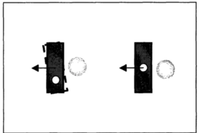
Figure 2.12: Placement of putter legs 3.5" back from the end of the enclosure to avoid contact with putter head
After constructing a prototype with the legs mentioned, it became evident that they could have been designed thinner to reduce the overall weight of the apparatus. The legs do also block the view of the user to a slight degree, so they should be made wider so that the user's view will remain as unobstructed as possible.
The bottoms of the legs in the first prototype were semi-circular wedges, and this will need to be changed to a half sphere to minimize the contact area with the table from a line to a point. This will aid the user with sliding the putter along the table without having to pick it up.
Figure 2.14: Bottom of putter legs in first prototype shown to have semicircular wedges on bottom
The new putter legs were optimized so that they provide sufficient lateral stability with an unobstructed view.
Figure 2.15: Optimized design for putter legs
The rounded legs also provide a nice feature from an aesthetic point of view, as the leg structure resembles a smooth arc. As you can see below, the view is no longer
obstructed.
Figure 2.16: User can clearly see putter head and ball through legs without any obstruction from legs
2.3.9: Aiming
The in-line putter will completely rely on user input for aim. With the legs resting on the table such that the putter head is near the ball, the user will adjust the angle of the putter with one hand so that the putter will strike the ball when the axis of the putter enclosure is on the same line as that made between the ball and the hole. At this point, the shot is completely set up, and the user will simply pull the trigger to strike the ball. This setup encapsulates the beauty of this design: the aiming and shooting elements of the putter have been completely decoupled. This will provide substantially increased
accuracy and control over the game for the user.
2.4: Linkage design
2.4.1: Input-.output motion interface
The goal in designing an in-line putter is to convert the finger motion at the grip/handle end of the putter to linear motion of the putter head along the axis of the line of sight aiming between the ball and the hole. As mentioned previously, this completely decouples the aiming and shooting aspects of game play. The user will be able to take a shot immediately after lining it up. There are several ways to achieve this end goal. The first question to ask is whether the user's hand motion is to be rotational or linear. It would be more difficult to convert rotational hand motion to linear motion at the end of the putter, but there are several things to consider here. If users have limited dexterity in their hands, it may be easier for them to rotate the handle above than translate something close to that handle linearly with one or two fingers. Also, the goal in making a tabletop golf game is to emulate several aspects of playing golf, and this ranges from the way the
table looks, to the nature of any hills, to the way you move your hands in using a putter. Many users may find rotating the above handle to be more of a golf-like action.
2.4.2: Trigger and placement
After considering these alternatives, it seems that having the user incite a linear response of the putter head by producing a linear response with his/her hand will be the optimal choice. This is essentially the simplest, and most straightforward design, and will produce a putter with better function, greater reliability, and less complications. There are also many ways to accomplish this linear response. The majority of practical designs involve some form of trigger system, and in order to satisfy the functional requirement of being able to use this putter with one hand, one must be able to easily access the trigger while holding the putter at its handle. This requires that the trigger be within 3 inches of the putter handle.
There are also several options in terms of where to put the trigger on the putter enclosure. The main options that stand out include putting the trigger on the top, bottom, or sides of the enclosure. This trigger will need to be hooked up to a bar linkage which will control the putter head at the front of the putter. In terms of this bar linkage
interface, the trigger can be built in to the top more easily, though this is not as natural for the user. I have decided that it will be optimal to place the trigger on the bottom of the enclosure. A complication comes up because it is naturally convenient to pull the trigger, rather than push. For the pull of a trigger to result in the putter head swinging outwards, the trigger will have to be pivoted towards the top of the enclosure.
It is also important to make sure that there is adequate tolerance in the putter enclosure and in the joint where the bar linkage is connected to the trigger so that it does not jam when it is translated linearly. Such jams severely limit the range of motion of this device [Slocum 2005].
Figure 2.18: Example of trigger jamming due to insufficient tolerance
IF
ip
2.4.3: Rod Linkage material
The vertical lever rod that the putter head is attached to is connected to the trigger by a rod linkage. Originally, a mockup was made with a 1/8" diameter aluminum rod. The problem with this design was the spring pin being used to join the trigger and shaft to this rod was of diameter 1/16". Also, aluminum would tend to buckle when it was under compression. When building the first prototype, a steel rod of diameter 3/16" was used. The front section was lowered to a diameter of 1/8" with a lathe so that it would fit in the
1/8" slot of the shaft.
2.4.4: Degrees of Freedom
The number of degrees of freedom of this bar linkage system must be calculated before we proceed further.
1111K
putter
pivot
link
trigger
pivot
Figure 2.19: Diagram highlighting links in bar linkage
For planar mechanisms, the degree of freedom (mobility) is given by Gruebler's
Equation:
F = 3(n - 1) -2f (1)
Here n is the total number of links, which in this case is 2, andfi represents the total number of joints, which in this case is 1. The two joints above each count for
f-0.5.
The total number of degrees of freedom of our system is 1 [Slocum 2005].
2.4.5: Grashof Criteria
It is also important to make calculations for this linkage. It will be necessary to anticipate types of motion through the Grashof Criteria: The sum of the shortest and
longest links of a planar four-bar linkage cannot be greater than the sum of the remaining two links if there is to be continuous relative motion between two links
[Slocum 2005]. This linkage system was specifically designed with this in mind so that the performance is smooth.
2.4.6: Force relationships
Force feedback is very important as it will allow the user to shoot with the desired strength necessary to get the ball to the hole without over or under-shooting. The putter was designed so that the trigger/bar linkage system provides a direct link to the swinging of the putter head. There is actually an amplification that will be described in detail below but the output force is simply a linear function of the input force.
Considering the variables presented in the figure below, we can calculate several key relationships.
Figure 2.20: Diagram showing key forces and dimensions in 4-bar linkage
In the above figure, F, is the user's input force, F2 is the output force at the putter
head, d, is the distance between the trigger pivot and joint with the bar linkage, d2 is the
distance between the putter shaft pivot point and bar linkage joint, and d3 is the distance
between the putter shaft joint and the center of mass of the putter head.
The input moment will equal the output moment in the above scenario:
Fld, = F2d2 (2)
F
2
=
F,
(3)
d2
To maximize the output force, we must maximize the ratio of dl, the distance between the pivot and bar linkage for the trigger, to d2, the corresponding distance for the
shaft. The putter was designed so that d, is as large as possible, and d2 is as small as
possible, given the constraints of the physical geometries in which these dimensions lie. The input impulse must also equate with the output change of momentum:
(FjAt),rigger = A(mV)putter (4)
L-+I
F1 represents the force applied at the trigger, At is the time interval that this force is
applied on, m is the mass of the putter head, and v is the velocity of the putter head immediately before striking the ball. Considering that the mass of the putter is constant, and the initial velocity is zero, the required input force can be reduced to:
my
F = t
(5)
t
This calculation is necessary to determine if the input force required to generate the desired momentum of the putter head is reasonable. The input force that the human finger can generate ranges from 0.05-0.50N[Fu 2005]. The input force required to generate the desired momentum, calculated in the following sections, is at the bottom of this range, so this can be easily done.
2.4.7: Assembly
1/16"• spring pins joined all parts that could not be linked together with a press fit. These pins are made of Type 420 Stainless Steel and come in various lengths to
accommodate different space requirements.
-Wail
_
Th,,kn
,a*
p
Figure 2.21: Type 420 Stainless Steel Spring Pins
gli
12.4.8: Friction issues with putter rod linkages
When the first prototype was made, there was a great deal of friction associated with the bar linkage. This resulted in a more difficult experience for pulling the trigger to get the putter head to strike the ball. After swinging and hitting the ball, the putter head would not return to the default vertical position even though it was pivoted above the center of mass as described earlier. The friction forces caused it to stay in place, and the user would have to undergo the inconvenient process of actually pushing the trigger with his/her finger to get the putter to return to its default position. There are several options for fixing this problem. The trigger itself was cut to be exactly 0.5" wide, which is also the width of the milled out section of the enclosure. Changing the putter width to 0.45" will allow for some slack, and the putter will still have only one degree of freedom since
it is secured by a pin at the top, which is constrained by the enclosure.
This does not appear to be the greatest source of friction. The bar linkage is rubbing up against the enclosure near the opening for the trigger as can be seen in the picture.
Figure 2.22: View of inner rod rubbing up against enclosure near trigger
This problem can easily be overcome by using a lathe to reduce the diameter during the 3" section where this rubbing is occurring from 3/16" to 1/8". There is one final issue in terms of how tight of a fit the spring pins will need to provide. The spring pin that passes through the top of the trigger and both ends of the putter enclosure is a source of friction. This spring pin will need to fit tightly into the putter enclosure, but will need to have some slack in the region where it passes through the trigger. This is because the trigger will need to rotate about this point and the friction in this joint will be minimized if it's not a tight fit. The holes for the putter enclosure at this location are to be drilled with a 1/16" bit allowing for a tight press fit. The hole at the top of the trigger which is along the axis of the aforementioned holes is to be drilled with a 0.0635" drill bit so that there is enough slack for the trigger to rotate about this point with minimal friction. For even better performance, loctite can be used at the ends of the spring pin
where it presses into the putter enclosure, while lubrication can be used at the middle section of the pin where the trigger rotates.
The linear actuating rod that is inside the enclosure and in contact with it near the trigger does not come into contact with it at any other points along the enclosure. There are a few other areas to consider in making sure that all major sources of friction have been eliminated. Next we will take a look at the front of the putter where there is a pin that passes through the shaft and presses into the putter enclosure. In this case, the pin needs to be tightly fitted into the putter enclosure. These two holes with be drilled with a
1/16" drill bit. The hole through the shaft that is along the same axis as the
aforementioned holes is to be drilled with a 0.0635" drill bit. Again, this is slightly larger than the pin diameter so that it can rotate freely and friction can be minimized. The same loctite/lubrication strategy is to be used here.
There are two other pins that play a key role with this bar linkage setup. The first is the pin that links the beginning of the bar with the trigger. This pin will need to be hammered through while longer than the width of the trigger. Then, the pin must be shortened and sanded down until it is flush with the wall of the trigger with a belt sander. If the pin extlends out of the wall even the slighted bit it may cause unnecessary friction by rubbing against the inner wall of the putter enclosure. This hole should be drilled with a 0.0635" bit to provide a bit of slack. A spring pin is also used to attach the inner bar to the shaft. This pin will need to be shortened once it has been hammered through so that it does not rub against the inner wall of the putter enclosure as well. This hole is also to be made with a 0.0635" drill bit to provide some slack.
2.4.9: Spring assistance
Despite taking all the steps mentioned above, it may not be possible to remove the internal friction to the point that the putter rod will always smoothly return to the natural vertical position. There are a few options that involve the attachment of springs that would aid in the process of naturally returning the putter to this position.
A linear spring (shown in red in the figure below) can be set up so that in equilibrium, when the spring is at its natural length, it perfectly reaches a point on the shaft. Then, the user pulls the trigger, which causes the vertical rod to rotate about its pivot point, and extend the spring. The stretched spring will then exert a force on the putter head causing it to return to its equilibrium position. For this to happen, the spring would have to be attached below the pivot point of the shaft on one end, and to the inner wall of the enclosure on the other end.
Figure 2.23: Assistance from linear spring
vot Point
A cleared up version of this graph is provided below to highlight the critical dimensions and properties that influence the behavior of this system. Please note that the length of the linear spring is y. Its displacement at any point is y-x.
Figure 2.24: dimensions
Cleared up version of linear spring/putter system highlighting key
Applying a force balance on this system along the x (horizontal) and y (vertical) axes yields the following:
F~ = Fx -F =0
Fs = k(y -x) .-. Fx = k(y -x) F = F - mg = O :.'F N =mgvot Point
Center of mass
an (20) (21) (22) (23)(24)
0.4-Now we must sum the moments. For convention, the moments will be summed along the z-axis (positive out of the page, negative in). The moments will be considered at the pivot point shown above, which will be referred to as point A.
SAZ
= -mgdsin(O) - k(y - x)L (25)cos(8) = L / t (26)
L = tcos(O) (27)
" A z• = -mgdsin(O) - k(y - x)tcos(O)
(28)
The above expression represents the restoring torque exerted on the putter after a shot has been taken which forces it to return to its default vertical position. The second term in the final expression represents the added moment caused by the presence of our linear spring. To increase the restoring moment we can increase the stiffness of the spring, k, or the distance of the spring attachment point from the pivot point of the shaft, t.
It would also be possible to accomplish this goal using torsion springs. One end of the spring would be attached vertically along the wall of the shaft. A thin section could be milled out of the putter rod so that the end of the torsion spring can be embedded, and this can be secured in place with one or two pins. The other end of the torsion spring would be attached to the wall of the putter enclosure.
2.4.10: Lowering center of mass for putter enclosure
Another thing that can be done to aid the problem of the putter not returning to its default position is to further lower the center of mass of the apparatus. Currently, the upper half of the shaft was made to have a wider diameter than the lower half in order to
act as a counterweight. This makes it easier for the user to swing the putter, as it requires less force. However, after building a prototype, it is evident that the user will still be able to swing the putter easily without the counterweight, and removing this upper section of the shaft will further lower the center of mass of the shaft/putter head combination. In turn, this will increase the distance between where the shaft is pivoted and the center of mass, causing a greater force to aid it in restoring to its upright position after a shot is taken.
2.4.11: Enhanced aiming
The ability to use reference points along the putter structure to aim is vital for the success of this design. One reference point is the top section of the shaft. This is
conveniently lined up by eye with the ball, and the hole. However, a straight line
between the upper section of the shaft, the ball, and the hole, does not ensure that the shot will be successful. This is because the putter can rotate 360 ° and still maintain this line.
The angle of the putter enclosure axis with respect to this line is what is important. For the shot to be successful, this angle would have to be zero meaning that it is along the line. This is somewhat difficult to line up exactly by eye. Setting up a thin, vertical extension to the top of the putter enclosure at the front end where it is held by hand would aid in this aiming process. This is very similar to the thin strip of metal that is placed on the top of gun barrels for aiming. Now, the user can create a line by eye that contains this thin strip, the top of the shaft, the golf ball, and the hole. This will naturally place the axis of the putter rod enclosure along this line so that it has zero angular deviation.
2.5: Handle & Grip Design
2.5.1: Limited dexterity putter handle
Many wheelchair riders have limited dexterity in their hands. If they are to hold and use the putter with one hand, a disabled-friendly handle must be used. The comfort grip adjustable handle is very user friendly and provides good control over the putter. It is made of a comfortable texturized soft thermoplastic elastomer that reduces fatigue and provides excellent grip. The core is made of polypropylene. The outer diameter of the attachment point is 0.625.
Figure 2.25: Comfort grip adjustable handle
2.5.2: Putter grip
The putter may also be held by the first few inches of the putter enclosure as opposed to the handle. For this reason, a grip must be selected which will provide nice aesthetic qualities as well as appropriate control. The following grip has been chosen for this design. It is made of heavy-duty nonslip vinyl for strength and durability, and can withstand a temperature range of -20' to +180'F.
Figure 2.26: Putter grip
The grip comes with one closed end, which can be removed by a band saw. Both ends need to be open so that the handle can be attached at the end. Also, a section will need to be milled out at the bottom of the grip to match the section that has been milled
out of the putter enclosure for the trigger; this was done by placing the grip around a piece of aluminum tubing so that it is pulled taught. At this point the section was milled
out of both the grip and aluminum. The grip will then be extracted and any stray edges can be removed with a blade. The grips provide a very tight fit and must be inserted onto the enclosure after lubricating the inside with soapy water. The soap will eventually dry
Chapter 3: Prototype Evaluation
The final design accomplished all of the functional requirements. Feedback was solicited from 10 users who tried out the inline putter and compared it to the putter made by the 2.009 Red Team. A quantitative scale will be used to describe the users'
satisfaction with several components of the design. The scale is set up as follows: 1-poor, 2-unsatisfactory, 3-satisfactory, 4-good, 5-very impressive. The table below shows the average user feedback rating for how well the design met each of the functional requirements.
Table 3.1: Average user rating for how well the design met the functional requirements
Can use with one hand Light weight
Can rest on table for support Rely on user input to aim
Aim and shoot without shifting position Respond to user input of force control Strong follow through on shot
Repeatable action Visually appealing
The putter was completely usable with one hand. The users were able to hold the base of the putter enclosure with one hand near the base when moving the putter around the table. The grip at the beginning of the shaft was well received by all of the users who tested the putter. The users said that the grip was comfortable and helped them identify where to hold the putter. A few users also mentioned that the grip was a nice feature since the exposed section of the aluminum putter enclosure was cold and not very
~~~~·k
comfortable to hold by hand. The handle was also a desirable feature for most people. Many users liked using the handle to laterally translate the putter when it was resting on the table. The users were easily able to pull the trigger while holding the putter at the handle. Most users commented that having a black grip and a black handle made holding the putter at the right place very intuitive for the user. They mentioned that it was very easy to learn that there are two main ways to hold the putter: at the grip if you want to pick the putter up off the table and at the handle if you want to slide the putter forward, backward, or sideways while one end is rested on the table.
The putter achieved the desired light design, weighing in at a total of 2.05 pounds. Almost all of the users surveyed had no problem lifting the putter with one hand and moving it around the table. A few users had trouble lifting the putter when holding it at the very end, due to the length. These users simply slid their hand towards the middle of the putter and lifted it at this point without any trouble. Shortening the length of the putter would not help much with reducing the weight of the apparatus since the rod itself is made of aluminum, which is not very dense. Most of the weight of this apparatus is in the brass putter head, and the second largest contribution is in the legs. Both of these components were designed to be as light as possible to satisfy the functional requirements so the weight will not be an issue as long as users who are having trouble lifting it at the end lift from the middle. Shortening the putter is also undesirable since it limits the range over the table that the user can access from a fixed position. The putter was designed at the optimal length for a tabletop golf game such as Micro-golf by calculating the
The leg feature of the putter that enabled a user to rest it on the table at one point while holding the other end of the putter with one hand was very well received. Most users had no trouble moving the putter around from side to side or forward and backward while the putter rested on the table. One user commented "playing this game is really easy since you don't even have to pick the putter up off the table to move it around short distances." Some users found that the original design of the legs somewhat limited the view in front of the putter. The putter leg design was changed in light of this feedback so that the new design did not impede the user's view at all.
The :putter was designed to rely on user input for aiming. One wheelchair rider commented that he enjoyed using this putter because there was still a lot of emphasis on his skill level as far as aiming and force input. He commented, "I am disappointed that many games geared toward the handicapped are too easy. They are very boring since there is no element of challenge." The user will be able to take shots at any angle.
All of the users preferred the inline putter for many reasons. The main reason was that they were able to aim using a line of sight path, and shoot immediately afterwards without worrying about shifting position. A few users brought up the fact that playing pool was very difficult for them since it was hard to hold the pool stick in exactly the same position in the brief stage between aiming and shooting. They mentioned that it was very easy to hold the putter at this aimed orientation since the front end of the putter naturally rested on the table using the legs. The users were not satisfied with the standard putter since they had to line up their shot and then maneuver around the table to a point where they could shoot along a 90-degree angle to the original line of sight path. This proved to be a very inconvenient process for them. After moving, it was hard to find the
angle that was exactly 90 degrees from what they had lined up using a line of sight path. This severely limited the control that the user had over the game in Micro-golf and was the largest obstacle to its success. The users all preferred the inline putter. One user said, "This putter is clearly superior. You just line it up and shoot. Piece of cake, you don't ever have to move in between."
The users had no trouble varying the intensity of their shots by pulling the trigger faster. Most were impressed by how powerful the putter was, and how easy it was to make forceful shots. Additionally, users were able to make very soft shots for short-range putts. One user commented, "This putter is great. With the trigger system, you have total control over how hard you hit the ball."
The putter provided a strong follow through on all shots. After running several tests of hittinig the ball with different force levels, it was noted that the overall apparatus remained in place while the putter shaft and head swung and hit the ball. This ensured that linear momentum was transferred from the putter head to the ball in the most efficient manner.
It was very important to design the putter so that the action of shooting was easily repeatable. The first prototype made had problems in this area. The putter shaft would not return to its default vertical position after a shot was taken due to the internal friction
of the apparatus. Many users were disappointed because they would shoot the ball and then have to manually return the putter shaft to its vertical position by pushing the trigger
forward. This is not only inconvenient but also difficult for users that have limited dexterity. This problem was corrected and the putter design was optimized through two main adjustments. First, the counterweighted section at the top of the putter shaft was
removed, thus lowering the center of mass of the putter shaft and head combination. This lower center of mass leaves a larger distance between the center of mass and the pivot point, which results in a larger restoring moment. Also, the trigger was thinned out a bit and the linkage interface between the inner rod and the trigger, as well as the inner rod and the putter shaft were smoothed out and lubricated to ensure minimal friction.
Many of the users found the putter to be visually pleasing. One gentleman said that it looked liked a very appealing toy for him to play with. Others commented that they liked the coordination of colors, where everything was black, silver, or brass. The parts were finished off using high-density sand paper to provide a nice shine. One gentleman commented "it's shiny, looks good, and works well, what more could you ask for?"
The overall cost of the putter was between $40-45. This accomplished the overall goal of less than $50. The putter was also compact and robust. Wheelchair users were able to maneuver around a table while holding the putter in one hand without any trouble. One woman commented "the rod is so thin that I can easily hold it in my hand while I spin my wheels to get around the table, it's not a problem at all." The putter was also dropped on the ground several times to ensure a sturdy design. It functioned perfectly well after these drop tests.
Chapter 4: Conclusion
It was determined that the design shown below is optimal for an in-line putter to be used in a tabletop golf game such as Microgolf.
Figure 4.1: Optimized putter design
This lightweight putter can be used with one hand to shoot the ball and perform all required functions of the game. The front end rests on the table through aluminum legs that are curved so that they do not impede the player's vision. This putter completely relies on user input for aiming, as the user lines the putter up with a line between the ball and the hole. The ball can be shot immediately after aiming. The four bar linkage with the trigger system allows the user to control the amount of force produced with each shot.
The putter was made to be stable laterally and along the axis that the shaft swings through. The inertia of the components was set up so that the proper amount of
momentum can be transferred to a golf ball, while the rest of the apparatus remains in place. The center of mass of the shaft and putter head combination was specifically designed to be below the pivot point of this combination with respect to the enclosure so that the shaft returns to its default vertical position after each shot. This will ensure that
shooting is an easily repeatable action. The color scheme was chosen to make the putter as visually pleasing as possible. The components of the putter were also chosen so that the overall cost was less than $50.
The key element missing in the game of Microgolf designed by the 2.009 Red Team was control over the shooting aspects of the game, mainly because of a mediocre putter. The in-line putter designed and outlined in this thesis provides superior control over such tabletop golf games, and was very well received by a group of disabled
individuals who tested it out and gave feedback. This easy to use, new putter design will help even the playing field between able-bodied and disabled individuals.
Bibliography
Centroid, Area, Moments of Inertia, & Radius of Gyration of Rectangular Areas. 2007. <http://www.efunda.com/math/areas/rectangle.cfm>
Elert, Glenn. Mass of a Golf Ball. 1999.
<http://hypertextbook.com/facts/1999/ImranArif.shtml>
Fu, Chia-Yu. Direct Measurement of Index Finger Mechanical Impedence at Low Force.
2005.
How to Play - Riches - Croquet - Finer Points. 2004.
<http://www.oxfordcroquet.com/coach/riches/finer/index.asp> Kool Pool: 2.009 Final Presentation. 2002.
Putter Fitting at Golf Galaxy. 2007.
<http://www.golfgalaxy.com/galaxy/dept.asp?sid=0&deptid=96> Slocum, Alexander H. Linkages and Triggers. 2005.