Develop and Test
an Internally Cooled, Cabled Superconductor (ICCS)
for Large Scale MHD Magnets
Analysis Report
Hatch, A.M., Marston, P.G., Tarrh, J.M.,
Becker, H., Dawson, A.M., Minervini, J.V.
January 1986
Plasma Fusion Center
Massachusetts Institute of Technology
Cambridge, Massachusetts 02139 USA
This work was supported by the U.S. Department of Energy, Pittsburgh Energy Technology
Center, Pittsburgh, PA 15236 under Contract No. DE-AC22-84PC70512. Reproduction,
translation, publication, use and disposal, in whole or part, by or for the United States
Government is permitted.
NOTICE
This report was prepared as an account of work by an agency of the United States
Government. Neither the United States Government nor any agency thereof, nor any of
their employees, makes any warranty, express or implied, or assumes any legal liability or
responsibility for the accuracy, completeness, or usefulness of any information, apparatus,
product, or process disclosed, or represents that its use would not infringe privately owned
rights. Reference herein to any specific commercial p-oduct, process, or service by trade
name, trademark, manufacturer, or otherwise, does not necessarily constitute or imply
its endorsement, recommendation, or favoring by the United States Government or any
agency thereof. The views and opinions of authors expressed herein do not necessarily
state or reflect those of the United States Government or any agency thereof.
Table of Contents
Page No.
1.0 Introduction 1
2.0 Summary
1-2.1 Magnet Analysis Summary 1
2.2 Conductor Analysis Summary 2
3.0 Analysis 3
3.1 Magnet System Analysis 3
3.1.1 Electromagnetic Analysis 3
3.1.2 Structural Analysis 9
3.1.3 Thermodynamic Analysis 17
3.1.4 Electrical and Protection System 20
3.2 Conductor Analysis 20
3.2.1 Structural Analysis 20
3.2.2 Thermodynamic and Pressure Dynamic Analysis 28
3.2.3 Protection 32
3.2.4 Definition and Design of Experimental Setup 36
4.0 References 37
Appendix A Coil Model Generator Computer Program Listing 38
Appendix B List of Symbols 41
List of Figures
Fig. No. Page No.
1 Sketch of Tapered Rectangular Saddle MHD Coil with Ends at 4 Arbitrary (Specified) Angles
2 Typical Computer Model for Electromagnetic Analysis, 5 With n x m = 2 x 5
3 Diagram of Magnetic Forces Developed by Magnet Winding 10
4 Diagram of Magnetic Forces per Unit Length Developed by 11 Magnet Winding
5 Sketch of Winding and Force Containment Structure in Plane of 12 Peak On-Axis Field
6 Sketch of Winding and Longitudinal Force Contaiunent Structure 16
7 Electrical and Coolant Flow Diagram, Magnet Winding 19
8 Diagram of Emergency Discharge System 22
9 Sketch Showing Cross Section of Conductors in Conductor Bundle 25
10 Curves of Temperature Rise in Conductor vs. Current Density 34 in Copper, Magnetic Field = 0 T
11 Curves of Temperature Rise in Conductor vs. Current Density 35 in Copper, Magnetic Field = 6 T
List of Tables
Table No. Page No.
I Configurations Analyzed for Peak Magnetic Fields 8
II Magnet Structure Material Properties and Design Stresses 13
III Forces per Unit Length Developed by Magnet Winding 14
IV Estimated Pressures Developed by Magnetic Forces in Winding Bundles 18
V Estimated Heat Leakage and Heat Generation in Winding and Cold 21 Region of Magnet
VI Emergency Discharge Voltage and Conductor Temperature Rise for 23 Various Discharge Time Constants
VII Conclusions From Exploratory Tests of Nb3Sn ICCS under Transverse Load 27
VIII
Requirements, Dimensions, and Construction -Conductor for Early 29 Version Preconceptual Design MagnetIX Calculated Characteristics - Conductor for Early Version 30 Preconceptual Design Magnet
X Revised Requirements - Conductor for Early Version 31 Preconceptual Design Magnet
XI Major Parameters and Calculated Characteristics - 33 Alternative Design Conductors Based on Revised Requirements
1.0 hitroduction
A three-year program to develop and test an internally-cooled cabled superconductor (ICCS)
for large-scale MHD magnets is being performed by MIT for the Pittsburgh Energy Technology Center (PETC) under contract DE-AC22-84PC70512.
The program consists of the following four tasks: I. Design Requirements Definition
II. Analysis III. Experiment IV. Full Scale Test
This report describes the analysis performed (Task II) in the period from the start of the program on August 21, 1984 through December 1985. It represents a progress report. Analysis is an ongoing effort which will continue in support of the testing, Tasks III and IV, and will be reported on again in the future.
Included in this report are electromagnetic, thermodynamic, structural, protection, and sys-tems analyses, completed as required to substantiate the preliminary conductor design requirements definition and the associated preconceptual magnet design developed in Task I. (It was necessary to generate the design for a retrofit-size MHD magnet as a basis for establishing the characteristics and design requirements for the conductor.) Magnet and conductor designs are largely interdepen-dent, and it was therefore appropriate to develop them in parallel. The magnet design could not be fully substantiated until after the conductor was defined.
Not included are analyses required to establish limits for conductor internal flow resistance and length between vents, and t'o support small-scale test conductor design, test equipment designs, and test plans. This work, not accomplished as of the date of this report, will be covered in a future report.
Copper-stabilized NbTi superconductor was selected at the outset as being most suitable for the application because
1. this superconductor has adequate current-carrying capacity at the magnetic fields required in
magnets for linear MHD generators (4 to 8 T),
2. is easier and less expensive to manufacture and fabricate into coils than alternative supercon-ductors such as Nb3Sn, and
3. represents the commercially-available superconductor for which the greatest backgound of
ex-perience exists. 2.0 Summary
2.1 Magnet Analysis Summary
The analysis necessary to substantiate the preconceptual MHD magnet design is complete, including field and force calculations, preliminary structural analysis, thermodynamic (cryogenic) analysis, and the analysis of the magnet electrical and protective systems.
A significant result of the field analysis is the determination that maximum fields to which the
of the program, it was estimated that maximum field for the conductor would be about 6 T, 33% above the peak on-axis field of the magnet. This relationship was consistent with the characteristics of existing MHD designs using bath-cooled conductor. However, when the initial ICCS winding design was analysed, maximum field was found to be 7.6 T (69% above central field) making the design unacceptable from the standpoint of stability. The high maximum field came about because of the relatively high winding current density achievable with ICCS, a feature advantageous.in reducing magnet size and cost, but also resulting in the higher maximum-field-to-central-field ratio inherent with thin windings.
Changes were made to produce a revised design in which the maximum field is 6.9 T (53% above central field) and adequate stability is ensured.
The impact of the analysis and design revisions on conductor requirements is to reduce design current and current density by about 25% from initial values. The revised conductor and winding current densities are still substantially higher than those of magnet designs incorporating bath-cooled conductor.
The preconceptual magnet design is described in a Technical Progress Report.' The analysis done in support of the magnet preconceptual design is described in Section 3.1 of this report.
2.2 Conductor Analysis Summary
Analysis necessary to substantiate a preliminary conductor design requirement definition for full-scale conductor has been completed except that further work is required to establish maximum allowable internal flow resistance and maximum length between vents. Procedures for accomplishing these analyses have already been developed at MIT and by other contractors.5
Structural behavior of the full-scale conductor has been examined, based on exploratory tests previously performed.2 Thermodynamic analysis has been performed on several alternative conduc-tor designs to determine stability and quench heating characteristics, together with the analysis of pressure dynamics and of conductor heating under magnet emergency discharge conditions. Stress-ful conditions are imposed on the conductor both by the high internal pressure caused by quench heating and by the high temperature caused by emergency discharge. It was necessary, therefore
to analyse these effects for all candidate conductors.
Further conductor analysis is required to finalize specific design parameters such as the copper-to-superconductor ratio, stability margin, and quench heating temperature rise. This analysis must be sequenced subsequent to the test results obtained under Tasks III and IV.
A listing of conductor design requirements in preliminary form is contained in the Design Re-quirements Definition Report. The design reRe-quirements definition will be finalized upon completion of the conductor analysis and tests.
The definition and design of the experimental setup for conductor testing, including predictive analysis, will be initiated in the next period.
Analysis accomplished to date in support of conductor design requirements is described in Section 3.2 of this report.
The analysis performed to substantiate both the preconceptual magnet design and the con-ductor design requirements definition is described below.
3.1 Magnet System Analysis 3.1.1 Electromagnetic Analysis
In order to perform the electromagnetic analysis, it was recognized that detailed three-dimension-al computer modeling would be required to determine adequately the basic magnetic parameters, including: field profile on axis, field distribution in the magnet bore (homogeneity), fringe magnetic fields, peak fields at the winding, and magnetic forces. The first step in the analysis was thus to select an appropriate configuration, and then to develop a computer model for this configuration. The configuration selected was a tapered rectangular saddle coil, having end turns at an angle to the symmetry plane between coils. A rectangular saddle coil configuration was selected because it allows the warm bore of the magnet to be rectangular in cross section (rather than square or round), thereby providing more effective use of the high field volume. The coil taper allows for insertion of a tapered channel, while providing the desired taper in magnetic field along the channel axis. The end turn configuration provides maximum access to the flow train at both ends of the magnet by allowing the cryostat end surfaces to slope inward toward the magnet bore.' A sketch of this configuration is given in Fig. 1, including all of the parameters necessary to define a specific case, as well as a coordinate system for reference. Each coil is modeled using an nxm matrix of filaments, with n filaments through the coil width w and m filaments through the coil height h, where a filament is a sequence of straight, finite-length current-carrying elements of negligible cross section which are linked together end to end to form a loop around the coil. For this configuration, 16 such straight elements are required to form a complete filament. In the actual coil design, a finite cross-section conductor will be wound to provide a continuous current path of many turns in series filling the same envelope as the array of closed loops used in the computer model. A listing of the computer program that was written to generate the required filamentary models, based on this configuration, is included as Appendix A. A typical model, generated using the program with n x m = 2x 5, is shown in Fig. 2.
It was originally anticipated that the electromagnetic analysis would consist of a rather straight-forward application of the modeling techniques that have been described. Thus for a given set of parameters (i.e., a fixed geometry), the computer model would be generated (such as that shown in Fig. 2) and the most basic characteristics determined (field profile for a current density appropriate to the conductor under development) using existing computer programs to analyze the model. The model parameters would then be adjusted, as necessary, to obtain a satisfactory, self-consistent set of design parameters.
-! 1
3-aa
w
Fig. 1 Sketch of Tapered Rectangular Saddle MHD Coil with Ends at Arbitrary (Specified) Angles
z
x
ZI X(RR
h
h
0ho
h-
i...
bo
\v.%*. \ -'A'.".
K'~
~
Y
Fig. 2 Typical Computer Model for Electromagnetic Analysis, With nxm = 2x5
This process was performed without difficulty until the peak magnetic fields at the winding were first calculated. The peak field calculation is typically performed after the other parameters have been determined. Although the peak field value is extremely important in that it determines the maximum field to which the, conductor will be exposed (and is therefore a critical parameter relative to conductor design and specification), it is a difficult and tedious calculation to perform. This is true because one must address the approximations inherent in the computer model relative to what the actual coil configuration would be, and then search throughout the model to locate the maximum field value at the winding. An effective approach is to assume a value for the ratio of the peak field at the winding to the maximum field on axis (based on experience with similar configurations), and use this assumed ratio to design the coil and conductor, and then verify that the actual peak field is acceptable.
The first detailed calculations of peak field at the windings gave results considerably higher than anticipated (approximately 7.6 T). This value of maximum field was incompatible with the planned conductor design, which was intended for use with a maximum field well below 7 T. To modify the conductor for operation in the higher field at the originally planned high current rating, more NbTi superconductor would need to be added, which in the fixed conductor envelope would result in removal of some of the copper and a significant reduction in the copper-to-superconductor ratio, which adversely affects stability.
NbTi has a relatively low critical field and hence its current-carrying capacity drops off rapidly at fields above 7 T. Calculations showed that it was impossible to achieve acceptable stability and safety margins without reducing the maximum field and/or the conductor current rating. It was clear that effort should be spent to determine how much reduction in maximum field could be achieved by modifying the coil configuration, after which tradeoffs would be made to arrive at a final set of characteristics (coil configuration, conductor current rating, maximum field and stability criteria) suitable for an early commercial magnet. In order to address this issue, the impact of various changes in the original configuration parameters on the peak field were examined by analyzing a number of different cases. The parameter values for four of these cases are listed in Table I. The parameters listed in the table correspond directly to those shown in the configuration sketch of Fig. 1 and to the list of input required for a particular case in the computer program listing of Appendix A.
Among these four cases, all of the currents were adjusted to achieve a maximum on-axis field of 4.5 T. Case I is the original configuration. Case II is similar to Case I, but with extended end turns and larger corner radii. Case III is similar to Case II, but with a 22% greater coil cross-sectional area, as well as a greater coil width-to-height ratio. Case IV is similar to Cases II and III, but with a 31% greater area than Case 11 (7.5% greater area than Case III) and an even larger width-to-height ratio than Case III.
The peak fields at the winding for the first two cases are approximately the same (7.2 T), although the location of the peak field for Case II is in the "straight section" (i.e., the long run of
end turns as well as within the straight section. For Cases III and IV, the peak fields at the winding are also approximately the same (6.9 T), and occur within their respective straight sections. A fifth case was also analyzed, consisting of 450 angles (rather than 600) and carrying a current of 5.97 MA turns, but otherwise identical to Case IV. This case reduced the peak fields only slightly, to a value of 6.8 T.
The results of this analysis were then confirmed by comparison to a somewhat more fundamen-tal, simplified approach. These results demonstrated conclusively that the only way to decrease the peak magnetic field at the winding to acceptable levels would be to decrease the winding current density and increase the coil cross section. Given this choice, a compromise of increasing the coil cross section (from Case I to Case III) was chosen, while accepting an increased peak field at the winding in the range of 6.8 to 6.9 T (in comparison to the originally assumed value of 6.0 T). This peak field increase impacted the conductor design by requiring a decrease in the current level for the same conductor cross section, as discussed in Section 3.2.2. The changes are actually self-consistent because increasing the coil cross section provides room for more turns of conductor, and when these extra turns are added, the design current in the conductor is automatically lowered to keep total ampere-turns at the required level.
The analysis of peak fields was a major result which significantly impacted the conductor design requirements. It should be noted, however, that the originally assumed ratio of peak field at the winding to maximum on-axis field, taken on the basis of earlier analyses and detailed calculations on larger, higher field magnets for base-load application, was confirmed by the present analysis. These higher-field magnets had substantially lower winding current densities and therefore much thicker windings. If the present analysis were applied to the earlier designs, peak-field-to-central-field ratios in the range of 1.33 would be obtained.
With the selection of Case III as the new baseline configuration, the electromagnetic analysis was completed with determination of the basic electromagnetic characteristics. These include the field profile on axis, field distribution in the magnet bore (homogeneity), and fringe magnetic fields. These results, as well as a diagram showing the location of the peak field at the windings and other high field points are given in a Technical Progress Report.'
The computer model described herein was also used to determine the magnetic forces on the windings. The results of this analysis are sununarized in Figs. 3 and 4 and Table II in the following section.
Table I
CONFIGURATIONS ANALYZED FOR PEAK MAGNETIC FIELDS
Parameter Case I Case II Case III Case IV
Coil length between ends, I (m) 9.01 9.01 9.01 9.01 Coil width, w (m) 0.25 0.25 0.305 0.40 Coil height, h (m) 0.61 0.61 0.61 0.50
Bore half-width at inlet, ai (m) 0.71 0.71 0.71 0.71 Bore half-width at outlet, a, (m) 0.96 0.96 0.96 0.96 Coil half-gap at inlet, bi (m) 0.08 0.08 0.08 0.08 Coil half-gap at outlet, b0 (m) 0.20 0.20 0.20 0.20
Crossover half-height at inlet, hi (m) 1.00 1.13 1.13 1.13 Crossover half-height at outlet, h0 (m) 1.24 1.37 1.37 1.37 Inlet end turn angle, Oi (0) 60 60 60 60
Outlet end turn angle, 0, (0) 60 60 60 60
End turn minimum radii, R (m) 0.15 0.30 0.30 0.30 Coordinate offset from inlet end, xi (m) 0 0 0 0 Total current per coil, I (MA turns) 5.872 5.918 6.04 6.0 Filaments through coil width, n (-) 2 2 4 4 Filaments through coil l;eight, m (-) 5 5 8 5
3.1.2 Structural Analysis
The magnetic force containment structure of the preconceptual design magnet was analyzed to verify its ability to withstand forces as determined by the electromagnetic analysis described in Section 3.1.1. The maximum allowable design stresses, listed in Table III, were used as a guide in evaluating the results of the analyses.
The magnetic forces developed by the magnet windings operating at design field strength are shown diagrammatically in Fig. 3. The forces developed per unit length in critical portions of the winding are listed in Table III and are shown diagrammatically in Fig. 4.
The 304LN stainless steel force containment structure around the winding in the plane of the peak on-axis field, which is located approximately 1 in downstream from the inlet-end turn-up of the winding, is shown in Fig. 5. The y-directed force per unit length on one winding bundle in this plane is 776 x 103 kg/m (43.4 x 10 lbs/in) as shown in Fig. 4. The beams are spaced on 20 cm (8 in) centers in the x-direction. The span between tie-rod centerlines is 224 cm (88 in) in the z-direction as indicated in Fig. 5. It is assumed that the beam is uniformly loaded and is point-supported at its ends.
Assumed loading and calculated stresses and deflections are as follows: Beam:
Total force on one beam (y-dir) 315 tonnes (693 x 103 lbs) Distributed load along length 1414 kg/cm (7.9 x 10' lbs/in)
Bending moment 858 x 103 Nm (7.6 x 10⁶ in lbs)
Maximum stress, bending 370 MPa (53.7 kpsi)
Maximum deflection (at center) 0.53 cm (0.21 in) Tie-rod:
Force on one tie-rod (y-dir) 157.5 tonnes (346.5 x 10³ lbs) Tensile stress 338 MPa (49 kpsi)
Deflection (half-length) 0.28 cm (0.11 in)
Since the calculated stresses in beam and tie-rod are below the maximum allowable design stresses listed in Table II for Type 304LN stainless steel at 4.5 K, the design is satisfactory. Prelim-inary calculations show an average stress of 55 kpsi at the thread root area of 6.324 in2, assuming threads are the 8N series. (See Fig. 5) When detail design is accomplished, the ends of the tie-rods should be examined to ensure that combined stresses in the region of thread roots are below the maximum allowable design stress.
Forces are in tonnes on One Half of Winding. One (metric) tonne
=
1000 kg.Total Axial ( X- Dir ) Force Outward on Each End of Winding (2 Coils)
-4136 tonnes 374 349 59.5 49.1 -L
1
226
--130 Y 78 6444 135 479X
419 6357 102" 154 lie 15590. 5 205225
~
9.
1009 11I61 - - .Z
X
.... -.... : zz
X
266
245
412 3
Forces are in tonnes/m
on One Half of Winding
(I
tonne = 1000 kg)Plane of Peak
on-axis Field -....---Y X 822 715L_/N
NOTE 1
644 654 776 866 NOTE1 326-865
---... 769 5 z XNOTE I
:
Fig. 4 Diagram of Magnetic Forces per Unit Length Developed by Magnet Winding
Z
X
Thread 3"- 8 N
(Min. area at thread root 6.364 in 2
) I-Beam 24
(88)
20.3
Fy (8) 1 '77Col
Form
*9 I~~~Coil
e Roa 7.6 Dia (3) 17.83.8
35.6
(.5) (14)3.8
(.5)
Dimensions in cm (in) Material-Type 304 LN Stainless SteelFig. 5 Sketch of Winding and Force Containment Structure in Plane of Peak On-Axis Field Y
z
X
Table II
MAGNET STRUCTURE MATERIAL PROPERTIES AND DESIGN STRESSES
Operating Temperature K Stainless Steel Type 304LN 300 4.5 Assumed Mechanical Properties TUS MPa (kpsi) 552 (80) 1655 (240) Maximum Allowable Design Stress (See Note 1) TYS MPa (kpsi) 379 (55) 621 (90) MPa (kpsi) 184 (26.7) 414 (60) es:
Maximum allowable design stress is taken as 1/3 TUS or 2/3 TYS, whichever is lower. See Reference 4.
TUS = Tensile Ultimate Strength TYS = Tensile Yield Strength
1 Pa = 1 N/mn2 Material Not 1. 2. 3. 4.
Table III
FORCES PER UNIT LENGTH DEVELOPED BY MAGNET WINDING
Stick* Projected Length (m)
x-y x-z y-z 1,6 9.01 9.01 0.277 1,2 0.18 0.18 0 2,3 0.32 0.65 0.565 3,4 0.20 0.179 0.26 4,5 1.312 0 1.312 Force (tonnes)
x-dir y-dir z-dir
-90.5 6357 -6444
0 118 -178
-233 419 -134
-225 155 49.1
-1009 0 349
Force per Unit Length (tonnes/m) x-dir y-dir z-dir
-326 705 -715
0 654 -990
-412 644 -419
-865 866 245
-769 0 266
x-dir. force is on y-z plane projection y-dir. force is on x-z plane projection z-dir. force is on x-y plane projection
Deflection calculations show that the windings will move away from the coil form during charging, approximately 0.76 cm (0.3 in) at mid-span. However, this amount of motion is acceptable for the type of highly stable winding proposed.
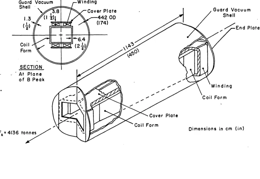
The force containment structure which resists longitudinal (x-direction) magnetic forces is shown in Fig. 6. The total longitudinal force acting outward at each end of the magnet is approx-imately 4136 tonnes (9.1 x 10⁶ lbs). The major portion of this force is carried by the end plates which transmit it to the structural elements (coil form, cover plates, etc.) running longitudinally from end to end. The cross-sectional areas of structural elements at the plane of peak on-axis field (reference plane) are as follows:
Area Structural Element (cm2) (in2) Coil form (6.35 cm thick) 4031 625 Cover plates (3.81 cm thick) 1355 210 Guard vacuum shell (1.27 cm thick) 1761 273 Conductor sheath (0.165 cm thick) 922 143
(672 conductors)
Total 8069 1251
Calculated tensile stresses at the reference plane under various assumed conditions are as follows:
Stress
Assumed Condition (MPa) (kpsi)
Load distributed to all elements 50.1 7.27 Load carried by coil form and guard vacuum shell 69.9 10.13 Load carried by coil form only 100.4 14.56 Load carried by vacuum shell only 229.9 33.33
The coil form, cover plates, and guard vacuum shell are of 304LN stainless steel operating at 4.5 K, for which the maximum allowable stress is 414 MPa (60 kpsi) according to Table II. Based on this analysis, the stress in the longitudinal load-carrying structure is very low (conservative), even
when the load is unevenly distributed.
The reason that the calculated stresses due to longitudinal loads are relatively low is that the elements are designed based on other considerations . For example, the coil form is designed with 6.35 cm thick walls to limit y-direction deflection (bending) of the coil-supporting walls of the coil-form cross section under the effect of coil clamping preload to < 0.8 cm, and to limit bending stresses to < 414 MPa (< 60 kpsi).
Guard Vacuum Shell
1.3
0 a
Coil
FormSECTION
At Plane of B Peak Fx= 4136 tonnes WindingCover Plate ,Guard Vocuu
442 OD
(174) End 6.4 (2 ) -' Winding Coil Form Cover PlateCoil Form Dimensions in cm (in)
Fig. 6 Sketch of Winding and Longitudinal Force Containment Structure
m
These preliminary structural analyses indicate that the major elements of the preconceptual design are conservative from a structural standpoint. When the design is carried beyond the preconceptual stage, further structural analysis will be necessary to verify details of the design including fastenings, structural supports in the region of end turns, etc., and to optimize the design for the most economical use of material.
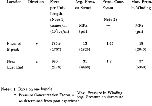
The pressures developed by magnetic forces in the winding bundles against the containment structure in critical areas and the maximum pressures within the bundles were estimated based on data contained in Fig. 4. The results are listed in Table IV. It should be noted that pressures shown are average for the bundle, assuming the insulation between conductors shares loading. If it is assumed that the insulation takes no load, then the pressure on the conductors themselves will be higher by about 27% in the y-direction and 8% in the z-direction. Tests performed on bundles of conductors of the type and size discussed in this report have shown the capability to withstand transverse pressures exceeding 50 MPa (7250 psi).2
3.1.3 Thermodynamic Analysis
This section contains a description of the thermodynamic analysis of the magnet and its wind-ing under steady-state operatwind-ing conditions.
Sources of heating within the winding were determined as follows. Fig. 7 is an electrical and cooling diagram of the winding showing a total of 14 electrical joints (conductor splices) in the two halves of the winding. Based on Westinghouse data5 , the resistance per joint is assumed to be approximately 2 x 10' 0. With a design current of 18 kA, the heating per joint is therefore approximately 0.7 W. This estimated joint loss is subject to change as more experience with ICCS joints is obtained.
Estimated heat leakage and heat generation in the winding and cold (4.5 K) region of the magnet from all sources are listed in Table V. The total equivalent refrigeration at 4.5 K is about 250 W. The magnet is so designed that all conductor splices are located outside of the winding and are immersed in a bath of liquid helium which removes the splice losses. This helium bath also intercepts heat entering through the stack. Therefore, the heat which must be removed from the winding itself consists of thermal radiation of 15 W, conduction of 10 W and flow friction heating of 25 W, for a total of 50 W. The helium coolant flow of 48 g/s, passing through the winding as shown in Fig. 7, removes this heat with a temperature rise of about 0.1 K. The pressure drop in the helium circuit through the windings is estimated to be 0.7 atm. This analysis, necessary in order to establish maximum allowable internal flow resistance of the conductor, is preliminary and
will be updated when test data on sample conductors is obtained. *
* It should be noted that in the present design most of the 15 W radiation load will be intercepted by the guard vacuum vessel, thus reducing significantly the winding heat load and the pumping (flow friction) losses. In view of the fact that the guard vacuum vessel is a redundant risk preventative component determined to be prudent because of the lack of long-term (leak free) experience with ICCS (and may thus be eliminated in a future design) full losses have been included in the winding
Table IV
ESTIMATED PRESSURES DEVELOPED BY MAGNETIC FORCES IN THE WINDING BUNDLES
Location Direction Force per Unit Length (Note 1) tonnes/m (10l3bs/m) Avg. Press. on Struct. Press. Conc. Factor Max. Press. in Winding (Note 2) MPa (psi) MPa (psi) Plane of B peak Near Inlet End y 775.9 (1707) z 990 (2178) 13 (1820) 31 (4460) 1.45 1.2
Notes: 1. Force on one bundle
2. Pressure Concentration Factor = Max. Pressure in Winding Srered rAvg. Pressure on Structure as determined from past experience
18
(2640)
37 (5350)
I g/st Return at 300 K Cooled Lead 2 g/s I g/st 2 g/s1
Quadr. Pancake No. I
48 g/s from Refrigerator at 3.2 ATM. 4.5 K 22 g/s f 2g/st 2 to 5 w/s 6
4
F
t46 g/s Return to Refrigerator at 2.5 ATM. 4.6 K 22 g/s 24 /s 2 g/s -. -Length of Conductor In Pancake (m)1630 1375 Coil # I 6 Quadr. Pancakes Coil # 2 6 Quadr. Pancakes One Quadr. Pancake 14x4--56TurnsOne Coll a 6 x 56 a 336 Turns
Fig. 7 Electrical and Coolant Flow Diagram, Magnet Winding
I g/s Return at 300 K Cooled Lead ti g/s
Helium refrigeration equipment required for the proposed cryogenic system consists of con)-inercially available components and is not expected to require special development.
Cooldown and warmup subsystems have not been designed and analysed for the retrofit-size magnet, nor has cooldown time been calculated (cooldown time of about 4 weeks would be predicted based on past experience). It is expected that designs for these subsystems developed for other large magnets can be adapted for the retrofit magnet without special development.
Thermodynamic analysis of the conductor itself is described in Section 3.2. 3.1.4 Electrical and Protection System
The electrical and protection (emergency discharge) system, shown in Fig. 8, was analyzed to determine maximum discharge voltage and adiabatic conductor heating during emergency dis-charge. It was assumed that a number of voltage taps are installed in the winding (at splices or other appropriate locations) and connected to voltage sensing equipment designed to activate the emergency discharge system automatically in the event that a portion of the winding becomes resistive (quenches) due to mechanical or electrical disturbances or other causes. Activation is accomplished by opening the circuit breakers shown in Fig. 8, causing the magnet to discharge through the resistor shown.
In analyzing the emergency discharge system, consideration must be given both to the maxi-mum voltage across the coil and to the maximaxi-mum temperature to which regions of the conductor rise. Fast discharge results in high voltage across magnet terminals, but is advantageous in limiting the temperature rise in the resistive (quenched) portions of the winding to moderate values. Slow discharge results in lower voltage but higher temperature rise. The actual design will therefore represent a tradeoff between considerations of voltage and temperature rise.
Calculations were made for various discharge time constants (10 to 30 seconds) to determine the resistor resistance value, initial voltage across the winding and maximum temperature rise of the conductor during discharge. It was assumed that the initial current was 18 kA, the initial current density in the conductor copper was 10,500 A/cm2, and that the conductor heating was adiabatic (no cooling), which is a conservative assuniption. Results of this analysis are listed in Table VI. Adiabatic heating of the conductor is also discussed in Section 3.2.3.
A time constant in the range of 10 to 20 s appears suitable for the preconceptual design magnet because, for this range of time constants, voltages are not excessive and conductor temperature
remains well below room temperature. 3.2 Conductor Analysis
3.2.1 Structural Analysis of Conductor
The structural characteristics of the conductor were analyzed to determine its ability to with-stand tension and transverse loading due to magnetic forces and also internal pressure loading under quench conditions. All three loadings (tension, transverse and internal pressure) cause significant stresses in the conductor of a magnet such as the retrofit MIHD magnet and must be considered in establishing conductor design requirements.
Table V
ESTIMATED HEAT LEAKAGE AND HEAT GENERATION IN WINDING AND COLD REGION OF MAGNET
Heating (W) Radiation from 80 K thermal shield 15 Conduction through support struts 10 Conduction through
stack piping and misc. 10
Conductor splice heating 10
Friction loss due to helium flow in conductor 25
Total 70
Note: In addition to the above, 2 g/s of 4.5 K helium are supplied to cool the power leads, exiting at 300 K. The equivalent refrigeration for the lead cooling is about 180 W at 4.5 K.
DC Circuit
Breakers
4'
Magnet
Winding
Inductance,
L= 3 Henries
Emergency
Discharge
Resistor
Resistance
Power
Supply
Unit
(See Note)
R
(See Table
I
)
Power Supply Max Rating
18,
000
A
,
30
V
Magnet Charging Time,
O
to 18,000 A at
30 V = 30
min
Fig. 8 Diagram of Emergency Discharge System.
NOTE
:
Table VI
EMERGENCY DISCHARGE VOLTAGE AND CONDUCTOR TEMPERATURE RISE FOR VARIOUS DISCHARGE TIME CONSTANTS
Discharge Resistor Resistance (ohms) 0.30 0.20 0.15 0.10 Voltage Across Winding (V) 5400 3600 2700 1800 Conductor Temperature Rise (See Note)
(K)
95 155 260 600
Note: Assumes initial JCu = 10.5 x 10³ A/cm2
Discharge Time Constant (s) 10 15 20 30
In considering tension loading, it is noted that the conductor in the preconceptual design magnet is supported by structure around the entire outside surface of the winding except for the corners of the end turns, which are unsupported at their outside radii. The result is that hoop tension is applied to the conductors forming the inner portion of these corners, due to Lorentz forces. To verify that the conductor can withstand the hoop tension, a worst case is assumed in which an unsupported turn is exposed to the maximum field (6.9 T) perpendicular to the plane of the end turn. The radius of the inner turn is taken as 0.3 m. With the design current of 18 kA in the conductor, the hoop tension is approximately 3864 kg (8500 lbs). If the effect of a possible quench pressure of 76 MPa (11 kpsi) inside the conductor is added, the total tension in the conductor is approximately 4591 kg (10,100 lbs), resulting in a tension stress in the conductor sheath of about 379 MPa (55 kpsi). Since this is less than 2/3 of the yield strength of the sheath material which is 304 LN at 4.5 K (see Table II), the conductor is satisfactory for the maximum tension load expected. It should be noted that the conductor sheath will actually be in the cold-worked condition and will therefore have a higher yield strength than that given in the table.
Transverse loading of the conductor occurs within the winding where Lorentz forces tend to compress the conductor bundle. Since the preconceptual design magnet does not incorporate any internal support structure (substructure) within the winding, the compressive forces are cumulative and result in relatively high pressures within the winding in high field regions. From the electro-magnetic analyses (Section 3.1.1) it is determined that z-directed pressures up to about 37 MPa
(5400 psi) will exist in the straight section of the winding near the inlet end.
It is of interest to determine the compressive stress in the conductor sheath, assuming all the pressure load is carried by the sheath. (It is assumed that the cable itself and the insulation do not carry load.) Referring to Fig. 9, plane A-A, the area of sheath material in compression represents 14.6 % of the total area. Therefore, the compressive stress in the sheath is about 225 MPa (37 kpsi). Since this is well below 2/3 of the yield strength of the sheath material (304 LN), the conductor sheath wall thickness is adequate for simple compression loading.
A more comprehensive analysis of this type of conductor under transverse loading is described in Reference 2. Full-scale conductor samples similar to the preconceptual design MHD magnet conductor were compression tested at room temperature and at liquid nitrogen temperature at pressures up to about 152 MPa (22 kpsi). This work, performed as a part of the fusion program, used a conductor which was identical to the proposed MHD magnet conductor except for the following differences:
P
=37.24 M Pa
Az9zc
Dimensions
2.08
in
cm
.
-
0.178
Insul
a
sh/a
=
2
x 0.165
/
(2.08 + 0.178) = 0
A
0.165 Wal
ation
..
146 (14.6%)
FUSION PROGRAM MHD
CONDUCTOR CONDUCTOR
Sheath material JBK-75 304 LN
0.025 nun foil wrap
on cable (2 layers) yes yes
Superconductor Nb3Sn NbTi
Copper-to-superconductor
ratio 1.8 to 1 Range 5 to 1
to 8 to 1
Tests described in Reference 2 were run to determine the load-carrying characteristics of a) the conductor cable itself (top of sheath removed), b) stacks of conduits empty, c) stacks of loose
cable-filled conduits, and d) stacks of cable-filled conduits insulated and potted. Conclusions from these tests are listed in Table VII.
The conclusions of Table VII cannot be applied directly to an ICCS for MHD because the latter incorporates a lower strength sheath material and a cable containing a larger proportion of copper, which is expected to result in reduced mechanical properties. However, we can extrapolate
from the table to show that the proposed MHD ICCS is adequate for the intended purpose. For
example, the maximum acceptable loading of 152 MPa (22 kpsi) given in the table, reduced by the ratio of sheath material yield strengths (see Table 3.1.2-I) becomes about 90 MPa (13 kpsi) for the
MHD ICCS. This allowable loading is more than twice the expected actual loading of 37.2 MPa (5400 psi), indicating that the MHD conductor is a conservative design with respect to transverse
loading.
With regard to high internal pressure loading such as may occur under quench conditions, tests conducted by Westinghouse and ORNL indicated achievable cryogenic strengths of the order of 1000 atmospheres with conduits similar to those discussed here, presumably of JBK-75 material2
'7. In addition the following relation has been used in connection with the design of square headers for steam boilers,2
o = pw/2t
where a is the proportional limit (yield) stress of the wall material, p is the internal pressure, w
is the width of the rectangular section, and t is the effective wall thickness. Using this expression, maximum design internal pressures are determined as follows (for two assumed values of design stress, a):
Table VII
CONCLUSIONS FROM EXPLORATORY TESTS OF Nb3Sn ICCS UNDER TRANSVERSE LOADS 2
1. A fully wound and potted ICCS coil should be capable of surviving static Lorentz loading greater than 152 MPa (22 kpsi).
2. The presence of corner filler (or potting) undoubtedly is an important factor in achieving that strength.
3. The cable at 32% void fraction appears to support 20% of the pressure applied to the potted and filled conduit.
4. Nonlinear elastic behavior at small loads and (presumably) inelastic behavior at large loads yielded stress-strain curves without a recognizable straight-line region. The steepest slope was approximately 0.5 msi. It occurred at 86.2 MPa (12.5 kpsi) pressure on the stack of filled and potted conduits. A value of 7500 psi was found for the filled and unpotted conduits.
5. The presence of insulation fractures at the corner straight-to-arc transitions indicates high contact pressures at those locations.
Design Stress Internal Pressure (MPa) (kpsi) (MPa) (kpsi)
414 60 78 11.3 (768 atm) 552 80 104 15.1 (1027 atm)
The design stress of 414 MPa (60 kpsi) is taken directly from Table II for 304 LN (annealed) material at 4.5 K. The design stress of 552 MPa (80 kpsi) assumes that the yield strength of the conduit wall has been increased by > 33% through cold work. The higher design stress is 1/3 of the ultimate strength listed in the table.
Pressure testing of samples of ICCS with 304 LN sheath should be performed to finalize the design requirement concerning maximum allowable internal pressure.
3.2.2 Thermodynamic and Pressure Dynamic Analysis of Conductor
Thermodynamic and pressure dynamic analyses of the conductor were performed in parallel with work on the magnet preconceptual design. These analyses are described in this section.
A conductor intended for an early version of the preconceptual magnet design was analyzed early in the program (December, 1984). The major requirements for this conductor are listed in Table VIII together with the assumed dimensions and construction. The calculated characteristics of the conductor, including stability margin, quench temperatures, and quench pressures, are listed in Table IX. These data are based on a NbTi superconductor having a critical current density of 1300 A/mm2 at 6 T and 4.5 K.
The stability margin is the maximum energy that the ICCS can absorb without quenching when operating at design current, field, and temperature. Calculations of stability margin, includ-ing the effect of joule heatinclud-ing, were made with the aid of an existinclud-ing computer program. The maximum temperatures and pressures with all stored energy dissipated as heating in the conductor and contained helium are based on the assumption that there is no heat exchange with external structure, etc., and no flow of coolant to or from the winding.
From the data listed in Table IX, it appears that the conductor would be satisfactory for this application, except that the ability of the conductor to withstand the quench pressure of 917 atm associated with the length of 600 m between vents would need to be verified by pressure testing. The stability margin of 85 mJ/cm3 (including the effects of joule heating) is somewhat lower than used for fusion magnets, but is acceptable for the MHD application due to the significantly reduced transient requirements.
Changes in conductor requirements were found to be necessary early in 1985, as a result of further development of the preconceptual magnet design. In particular, it was determined that the maximum field in the winding was higher than originally estimated and that some reduction in average current density and in design current were necessary in order to maintain adequate stability margin. The revised requirements, used as a basis for further conductor analysis, are listed in Table X. Conductor dimensions and construction remain the same as in Table VIII.
Table VIII
REQUIREMENTS, DIMENSIONS AND CONSTRUCTION - CONDUCTOR FOR EARLY VERSION PRECONCEPTUAL DESIGN MAGNET
Requirements: Design current Critical current Ratio, I/I, ' Maximum field He coolant temperature He coolant pressure Stored magnetic energy Conductor total length
Conductor length between vents
Dimensions and Construction: Sheath outside dimensions Sheath corner radius, outside Sheath thickness
Number of strands Strand diameter Void fraction Sheath material
Superconductor composite material kA kA T K atm Mi km m 20 26.7 0.75 6.0 4.5 2.5 321 14.4 600 cm 2.08 x 2.08 cm 0.508 cm 0.165 - 486 mm 0.717 - 0.32 - 304 LN - NbTi/Cu
0 The ratio I/I, is the ratio of the design (operating) current to the critical current of the
conductor at the design (operating) temperature and maximum field in the winding. Critical current is the maximum current the conductor can carry without entering the resistive mode.
Table IX
CALCULATED CHARACTERISTICS"
CONDUCTOR FOR EARLY VERSION PRECONCEPTUAL DESIGN MAGNET Copper-to-superconductor ratio
Stability margin based on AzHb at constant density
Stability margin based on A HC
at constant density plus joule heating
Max. quench pressure, 600 m between vents
Max. quench pressure, 300 m between vents
Max. temperature of ICCS, all stored energy into heating conductor and
contained helium
Max. pressure, all stored energy into heating conductor and contained helium
-- 8.6 mJ/cm3 158.1 mJ/cm3 85 atm atm K atm 917 434 105 439
a) Characteristics are based on NbTi superconductor having a critical current of 1300 A/mm2 at 6 T and 4.5 K
b) AH at constant density is the amount of heat (mJ/cm3 ) absorbed by the conductor assuming the density of helium in the conductor remains constant and heat is supplied by an external disturbance only (no resistive heating due to transport current in conductor).
c) ZAH at constant density and joule heating is the amount of heat (mJ/cm3 ) absorbed by the conductor assuming helium density remains constant and heat is supplied both by external disturbance and by resistive heating due to transport current.
Table X
REVISED REQUIREMENTS
CONDUCTOR FOR PRECONCEPTUAL DESIGN MAGNET
Design current Ratio, I/I, Maximum field
He coolant temperature He coolant pressure Stored magnetic energy Conductor total length
Conductor length between vents
kA 15-20 - 0.75, 0.60 T 6.8-6.9 K 4.5 atm 2.5 MJ 490 km 18±3 m TBD
Three conductors of alternative design were analyzed, based on the revised requirements. The major parameters and calculated characteristics of these conductors are listed in Table XI. For each of these alternatives it was assumed that the stored magnetic energy in the winding was 490 MJ.
The first alternative, a 20 kA conductor with a design current to critical current ratio of 0.75, was found to have a stability margin including joule heating of only 9.5 mJ/cm3, too low to be acceptable. A variation of this conductor, having a design current to critical current ratio of 0.60, was analyzed to see if a change to the lower current ratio would result in better stability. The stability margin increased only to 13 mJ/cm3 , not a sufficiently high margin to warrant selection of this conductor. Furthermore, the associated reduction in copper would be detrimental to protection of the conductor.
The second alternative, a 17.5 kA conductor (current ratio 0.75) was found to have a stability margin including joule heating of 70.5 mJ/cm3
, which is acceptable for this application. However, the maximum quench pressure of 1107 atm (for the length between vents of 800 m) is somewhat above the range of design pressures discussed in Section 3.2.1 from the standpoint of structural adequacy. Whether this maximum quench pressure is considered acceptable or whether it will be lowered (for example, by reducing length between vents) will depend on the results of future tests including pressure testing of sample conductors. The maximum temperature and pressure reached, with all stored energy transferred into heating of the conductor, are within acceptable limits.
The third alternative, a 15 kA conductor (current ratio 0.75) was found to have a stability margin including joule heating of 106 mJ/cm3 , which is more than adequate for the application. Since this conductor appears to be unnecessarily conservative, it was not analyzed further.
The conductor design selected for incorporation into the revised preconceptual design retrofit magnet was a design falling between alternatives IA and II. It has a design current of 18 kA, a critical current of 24 kA at a maximum field of 6.9 T, a copper-to-superconductor ratio of 7.5 and an estimated stability margin (joule heating included) of 40 mJ/cm3. This conductor design was selected as the highest current conductor possible, taking into account stability considerations. As for Alternative II, the question of maximum quench pressure must be reviewed in connection with future tests.
3.2.3 Protection
The conductor was analyzed to determine its thermal characteristics with respect to the protec-tion system described in Secprotec-tion 3.1.4. A worst case was assumed, namely an emergency discharge from full design current with only a short section of conductor in the normal state. This section was assumed to be without helium coolant and to be thermally isolated from adjacent winding and structure (i.e., heating was assumed to be adiabatic). Calculations were made to determine the re-lationship of conductor (adiabatic) temperature rise to design current density in the copper current path and time constant for emergency discharge, assuming exponential current decay. Information contained in Reference 6 was used as a guide. The results of the analysis are shown in Figs. 10 and 11 which contain curves of conductor temperature rise as a function of design current density in the copper for various discharge time constants.
Table XI
MAJOR PARAMETERS AND CALCULATED CHARACTERISTICS
ALTERNATIVE DESIGN CONDUCTORS BASED ON REVISED REQUIREMENTS
Major Parameters Design current Critical current
Ratio, des. current/crit. current Field
Superconductor crit. current dens. Length between vents
Calculated Characteristics
Copper-to-superconductor ratio Stability margin based on
AH at const. dens. Stability margin based on
AH at const. dens. plus Joule heating Max. quench pressure
Max. temp. of ICCS, all stored energy into heating conductor and helium
Max. press., all stored energy into heating conduct. & helium
kA kA T A/mm2 m mJ/cm3 I 20 26.7 0.75 6.9 1000 700 6.37 123.5 mJ/cm3 9.5 atm K atm Alternatives IA II 20 17.5 33.3 23.33 0.60 0.75 6.9 6.8 1000 1035 700 800 4.9 194.8 7.72 126 III 15 20 0.75 6.8 1035 800 9.17 126 13 70.5 106 - - 1107 -- - 117 - - 489
AM DISCHARGE 50 20 10 5 300 - TI? CONSTANT (I) 200 -100 w
50-20 3 s 10 20Fig. 10 Curves of Temperature Rise in Conductor vs. Current Density in Copper, Magnetic Field = 0 T
400 B DISCHARCE 50 20 10 5 300 - TIVE CONSTANT
(u)
200 -C4, 100so
20
-I-3 5 10 20C'?IUNT DENS:TY IN CO??LE (kA/c: 2)
Fig. 11 Curves of Temperature Rise in Conductor vs. Current Density in Copper, Magnetic Field = 6 T
An example of the use of the curves in conductor and system design is given below: Design current in conductor
Magnet inductance
Discharge resistor resistance Discharge time constant Discharge initial voltage
Current density in copper, initial Est. field at conductor, initial Final temperature of conductor
(from curves Fig. 11)
18 kA 3 H 0.3 [ 10 s 5400 V 10.5 kA/cm2 6 T 95 K
If a discharge initial voltage lower than 5400 V is desired, the discharge resistance can be low-ered. This will increase the time constant, with a resulting increase in final conductor temperature. In a similar manner, trade-offs can be made among other parameters such as current density in copper, design current, etc.
3.2.4 Definition and Design of Experimental Setup
The definition and design of the experimental setup will be performed in the next period. As anticipated, the analysis performed to date indicates the need for certain special tests, including tests of full-scale conductor samples to determine their ability to withstand internal pressure in addition to tests to determine their stability, quench propagation, and internal pressure dynamics. These tests will be included under Tasks III and IV of this conductor development and test program.
4.0 References
1. Technical Progress Report for Period from January 1, 1985 to June 30, 1985, Develop and
Test an ICCS for Large Scale MHD Magnets, Plasma Fusion Center, MIT, Cambridge, MA, November 1985.
2. Becker, H. et al., Structural Behavior of Internally Cooled Cabled Superconductors Under Transverse Load, Plasma Fusion Center, MIT, Cambridge, MA, June 1985.
(DOE/ET-15013-151).
3. Design Requirements Definition Report for ICCS for Large Scale MHD Magnets, Plasma Fusion
Center, MIT, Cambridge, MA, November 1985.
4. Becker, H., Structural Design Basis for Superconducting Magnets, Draft, MIT/FBNML, 8 February 1980.
5. Phase 2 Final Report to Union Carbide Corp., Nuclear Div., (Contract 22X-31747C) by
West-inghouse Electric Corporation, STG Technical Operations Div., Advanced Programs Dept., E. Pittsburgh, PA, March 31, 1980 Vol. II, Part 4, p. 3-813.
6. Course Notes, Magnet Power Supplies and Protection, MIT Summer Session "Superconducting
Appendix A Coil Model Generator Computer Program Listing
c MODEL BUILDING PROGRAM FOR TAPERED SADDLE MHD COIL WITH ENDS
c AT ARBITRARY ANGLES BETWEEN 0 AND 90 DEGREES (NONINCLUSIVE).
integer p real i.len
open(.1,file:'REF1'.status-'new')
c INPUT FOR PARTICULAR CASE IS AS FOLLOWS:
len=9.01 w=0.40 h=0.50 ai=0.71 ao-0.96 bi=0.08 bo,0.20 hi=1.13 ho=1.37 ti=45.0 to=45.0 r=0.30 xi=0.0 i=5.97e6 n=4 c INPUT COMPLETE i=i/(float (n)*f loat (m)) ns=16 nf=2*n*m pi=3.14159265359 ti=ti*pi/180.
to=to*pi/180.
hic=bi+h+r*sin(ti) hoc=bo+h+r*sin(to) if(hi.lt.hic) go to 100 go to 200 100 continue hi=hic write(0.1200) write(0,1400) 200 continue if(ho.lt.hoc) go to 300 go to 400 300 continue ho=hoc write(O.1300) write(0.1400) 400 continue d=1.0-sqrt(2.0-0.5*pi)s=1.0
p1000
write(11,1000) pns.nf
c
MODEL UPPER COIL FIRST, THEN NEGATIVE z IMAGE.
500 continue do 700 kzlm do 600 j=1,n qj =float(j)-0.5 qkzfloat(k)-0.5 wn-w/float(n) hm-h/float(m) xl=xi
yi=ai+qj*wn
zl=s*(bi+qk*hm) x2=xi-(h-qk*hm)*tan(ti/2.0) x4=xl-(hi-bi)/tan(ti)-h*tan(ti/2.0)+h*qk/sin(ti) x4=x4-wn*qj*cos(ti) x3=x4+(I.0-d)*(r+qj*wn)*cos(ti) z3=s*(hi-r*sin(ti)+d*(r+qj*wn)*sin(ti)) y4=ai-r+d*(r+qj*wn) z4=s*(hi+qj*wn*sin(ti))y5=-y4
y6=-yl
x9xi+len y9=-ao-qj *wn zg=s*(bo+qk*hm) x10=x9+(h-qk*hm)*tan(to/2.0) xl2-x9+(ho-bo)/tan(to)+h*tan(to/2.0)-hm*qk/sin(to) x12=x12+wn*qj*cos(to) xll=x12-(I.0-d)*(r+qj*wn)*cos(to) zil=s*(ho-r*sin(to)+d*(r+qj*wn)*sin(to)) y12=-ao+r-d*(r+qj*wn) zl2=s*(ho+qj*wn*sin(to)) y13=-yl2 yl4=-y9 p=p+10 write(11.1100) pi,x1,y1,z1,x2.y1,z1 P=P+10 writs(II.1100) p.i.x2.y1,zi,x3,yi,z3 p-p+10 write(11.1100) p,i,x3,yi.z3,x4,y4.z4 p-p+10 write(11.1100) pix4.y4.z4.x4.y5,z4p=p+10
write(11.1100) pix4,y5.z4,x3,y6,z3P=P+10
write(I1.1100) p,i.x3.y6,z3,x2,y6.zi p=p+10 write(11,1100) p.i.x2.y6,zi.xly6,zipp=+10
write(11.1100) v~i.x1.ve.zl.xg vg zg
p=p+10
write(11,1100)
p=p+10
write(11,
1100)
p=p+10
write(11.1100)
pp+10
write(11.1100)
p=p+10
write(11,1100)
p=p+10
write(11.1100)
p=p+10
write(11,1100)
p=p+10write(11.1100)
600
continue
700continue
800 1000 1100 1200 1300 1400 , ,p.i.x9,y9,z9,xlOyg,zg
pi.xlO.y9,z9,xll,y9,zlI
pi.xll.y9,zll.x12,y12,z12 P.i,x12.y12,z12,x12,yl3,zl 2 p.i,x12,y13,z2,x11,y14,zil p.ixll.y14.zllx10,y14.z9 p,i.xlO.y14,z9,x9,yl4,zgp.i,x
9.y14,z9.xlyl,zi
if(s.lt.0.0) go to 800s=-1.0
go to 500continue
format(2x,3(i5,2x)) format(2xi5.2xlpelO.4,2x,6(Opf10.4)) format(' INPUT VALUE OF hi TOO SMALL.') format(' INPUT VALUE OF ho TOO SMALL.')format(' HAS BEEN ADJUSTED TO MINIMUM POSSIBLE VALUE.') end
Appendix B - List of Symbols
A amperes
kA kiloampere (103 A) MA megampere (106 A)
T tesla (106 gauss), magnetic field
m meter(s)
cm
centimeter(s) g gram(s)kg kilogram(s) (103 g) K degrees Kelvin
TUS tensile ultimate strength TYS tensile yield strength psi pounds per square inch
kpsi thousand pounds per square inch Pa pascal (1 newton/square meter) MPa megapascals (106 Pa)
tonne metric ton (103 kg) in inch lb pound N newton s second(s) W watt(s) 0 ohm R resistance, electrical DC direct current L inductance, electrical V volt Cu copper J joule mJ millijoule (10-3 j) Nb3Sn niobium tin NbTi niobium titanium
MHD magnetohydrodynamic