Plasma evolution in laser-irradiated
hollow microcylinders
By J. E. BALMER, R. WEBER,
P. F. CUNNINGHAM* AND P. LADRACH
Institute of Applied Physics, University of Bern, CH-3012 Bern, Switzerland
(Received 13 December 1988)
Hollow microcylinder targets, 200-300 pim in diameter, have been internally irradiated at up to 5 • 1014 W/cm2 with Nd:glass laser pulses directed through an axial entrance slit. The plasma evolution in the interior of the cavities was diagnosed with a pinhole imaging X-ray streak camera and a Nomarski-type interferometer. Plasma collision near the cen-ter of the cylinder is observed about 300 ps afcen-ter the irradiating laser pulse. The experi-mental results are confirmed by a one-dimensional Eulerian fluid code.
1. Introduction
In recent years, high-temperature, short-pulse laser-produced plasmas have attracted considerable interest as possible gain media in soft X-ray laser experiments. Experimen-tal evidence for XUV amplification was reported in plasmas generated from coated fibers (Jacoby et al. 1982), exploding foils (Matthews et al. 1985; Seely et al. 1985), and solid targets (Jaegle et al. 1986; Suckewer et al. 1985). Essentially, these schemes rely on free plasma expansion into vacuum, so that the resulting electron density profiles are convex, i.e., with the density maximum along the axis. Since in a plasma the refractive index (due to free electrons) is given by n = (1 - ne/nec)U2, where nec is the critical electron den-sity, refraction in a convex density profile may result in steering the X-ray laser beam out of the region of high gain (London 1988). As a consequence, the attainment of gain-length products required for saturation is prevented. Methods to avoid this difficulty have been proposed by various authors and include alternating the plasma expansion in oppo-site directions by oppooppo-sitely focused laser beams (Hagelstein 1983), bending the target to form a curved surface along the soft X-ray laser propagation direction (Lunney 1986), and confining the expanding plasma between two planar foils (Rosen & Hagelstein 1986) or by means of an external magnetic field (Suckewer et al. 1985).
A novel scheme for the attainment of high electron densities and a concave wave-guiding density profile has been pursued at this laboratory (Balmer & Weber 1988; Cunningham
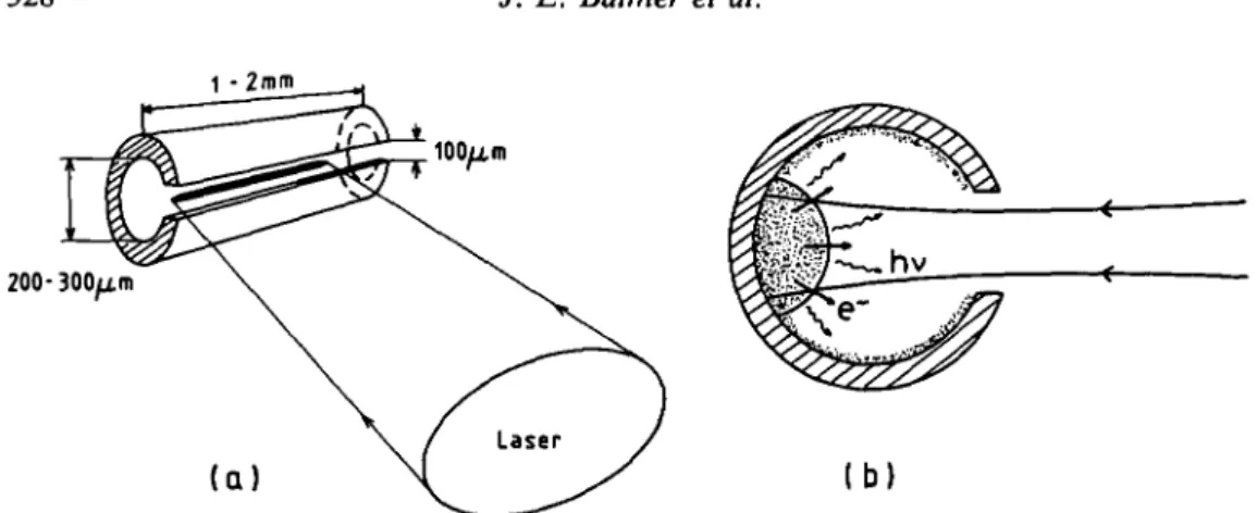
et al. 1988, Weber et al. 1988). As illustrated in figure la, plasma inside a hollow
micro-cylinder is produced by introducing a line focussed laser beam through an elongated aper-ture (slit) in the cavity wall. A primary plasma is then produced on the wall opposite the entrance slit. The remainder of the cavity's interior is subsequently exposed to laser light reflected at the primary spot, and to x-radiation and hot electrons emitted by the primary plasma. "Indirect" plasma generation thus occurs on the whole interior of the cavity, as shown schematically in figure lb. The time scale of this-process is determined by the di-ameter of the cavity, the speed of light and/or the velocity of the hot electrons. For the •Permanent address: Plasma Physics Research Institute, Department of Physics, University of Natal, Dur-ban 4001, South Africa.
1 - 2mm
200-(Q b)
FIGURE 1. (a) Schematic of microtube irradiation geometry through axial slit, (b) principle of indirect plasma generation by x-radiation, fast electrons, and reflected laser light.
parameters of interest in these experiments (200-300 jtm inner diameter, 0.5-1 keV elec-tron temperature), indirect plasma generation turns out to be instantaneous with respect to typical plasma expansion times. As a result, a radially symmetric flow of plasma con-verges towards the center. Since the material ablated from the wall is confined within the cavity, substantially higher densities and thus higher gains can be expected from such a target compared with the "open" geometries used to date. Also, in contrast to the pla-nar foil configuration (Rosen & Hagelstein 1986), plasma confinement is cylindrically sym-metric and true waveguiding is possible.
2. Experimental arrangement
The efficiency of indirect plasma generation and the subsequent plasma flow was ex-perimentally tested by irradiating 200 and 300 /*m diameter tubes fabricated from a range of metals like Al, Cu, Mo, and Au. The tubes are 1-2 mm in length and equipped with a -100 /xm wide entrance slit on one side, through which the Nd:glass laser beam can be focussed. The nominally 2-4 J, 80 ps pulses at 1054 nm produced an irradiance of -5-101 4 W/cm2 on the opposite wall. The entrance slit width of -100 nm was chosen to fit the 80 /*m focal spot diameter (l/e2-value) of the aspheric f/2 lens. In the case of irradiation with 500 /urn long line focus, a cylindrical lens of focal length -300 mm was inserted between the spherical lens and the target.
The plasma evolution within the cylinders was studied by means of a Nomarski-type interferometer (Benattar et al. 1979). A 527 nm probe beam was generated by frequency doubling a fraction of the 1054 nm main laser pulse in a type II KDP crystal. This al-lowed the 2o> critical density contour (4-1021 cm"3) and the steepness of the density gra-dient to be diagnosed on a shot-by-shot basis. The time of arrival of the 2w probe pulse with respect to the main laser pulse could be adjusted by means of a variable length opti-cal delay line. More details on the experimental arrangement can be found in Cunning-ham et al. (1988).
The X-ray emission from the microcylinders was recorded by means of a time-integrating X-ray pinhole camera equipped with four pinholes having diameters of 20, 27, 45, and 55 fim, respectively. A 12.5 ^m thick Be foil limited the observed spectrum to the region above - 1 keV. The temporal behavior of the 1 keV X-ray emission was diagnosed by means of a pinhole imaging X-ray streak camera with a temporal resolution of -25 ps.
The details of the experimental conditions are given in Weber et al. (1988). High resolu-tion X-ray spectra were recorded with a space-resolving miniature spectrometer equipped with a PET crystal. This covered the aluminum #-shell wavelength range between about 5 and 8 A. The spectra were recorded on Kodak DEF film. For observations along the cylinder axis the streak camera and spectrometer had to be used alternately.
3. Experimental results and discussion
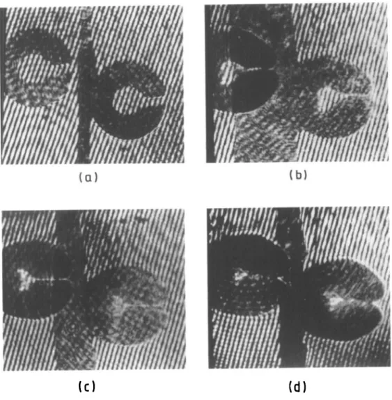
Figure 2 shows typical interferograms from a shot-by-shot temporal sequence of irra-diated Cu cylinders. Two images are seen on each photograph, one for each polarization of the probe beam. Figure 2a is an interferogram of a cylinder before irradiation. Each cylinder was first photographed in this way as a reference for the measurement of the various plasma movements. Figures 2b-2d show the plasma evolution at times 50 ps,
( a )
(b)(O
(d)
FIGURE 2. Interferograms of (a) un-irradiated Cu cylinder, (b), (c), and (d) irradiated Cu cylinders, probed at T = 50 ps, 100 ps, and 200 ps, respectively, after the peak of the laser pulse.
FIGURE 3. X-ray pinhole photographs of microtubes irradiated at 5-1013 W/cm2 (200 ps/527 nm).
(a) Au (200 nm inner diameter/75 ytm slit; (b) Mo (300/75). (Continued on facing page.)
100 ps, and 200 ps after the peak of the laser pulse, respectively. Plasma is seen to grow primarily from three areas on the inside of the cylinders; the directly irradiated region and two regions opposite, on either side of the slit. It is interesting to note from figures 2a and 2b that in the early phase of plasma expansion the fringes within the cylinder remain virtually unperturbed. We regard this as evidence of the very steep electron density pro-file produced by the short duration laser pulse. The details at later times (T s 100 ps) are not resolved well, but some perturbation of fringes at the center of the cylinders is observed.
FIGURE 3. (c) Al (300/100).
The cylinder's outer surface close to the slit is also seen to grow in a direction towards the main laser. This is consistent with on-axis time-integrating X-ray pinhole pictures shown in figure 3 which reveals that not all the laser light is focussed through the slit. It can be seen from the interferograms that the entrance slit is closed by plasma shortly after the end of the laser pulse, thus confining the plasma inside.
The position of the inwardly moving dark zones of both the primary plasma (at the back wall) and the secondary plasma (inside the slit) was measured at sequentially increasing times. Constant velocities of 2.7-107 and 1.5 -107 cm/s, respectively, were calculated, giv-ing a ratio of Q = 1.7. If one assumes that the plasma sound speed, cs, scales with Te as cs a (Z/Te/A)l/2, where Z is the ionic charge and A the atomic mass, then the ratio measured above leads to an estimate of the ratio of primary to secondary plasma electron temperatures of Tep/Tes = 2.9.
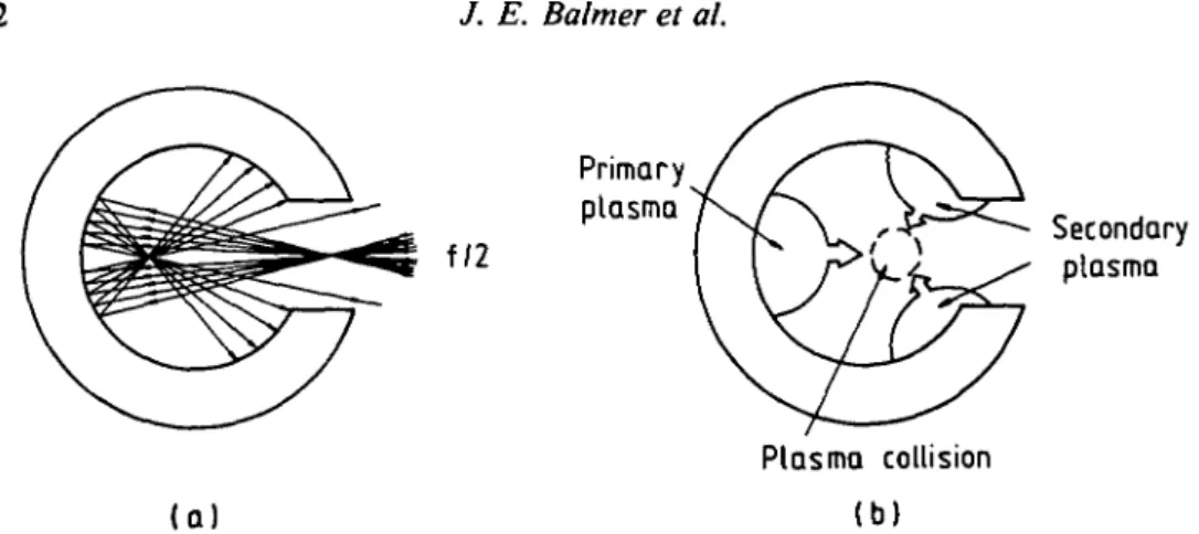
A simple ray tracing routine was used to estimate the distribution of the irradiating laser light within the cylinders. The geometric rays passing through the main beam waist (located at the entrance slit) are specularly reflected off the back wall and irradiate a cor-responding (larger) area on the inside front wall. Results of a ray tracing calculation and the subsequent plasma generation are shown in figure 4 for the case of f/2 focussing op-tics. It is clearly seen that the distribution of the laser light after a single reflection at the primary spot exactly reproduces the areas of plasma ablation observed in the inter-ferograms. This implies that reflected laser light is the dominating mechanism for indirect plasma generation under the conditions of our experiment (short pulses, long wavelength laser). A substantial fraction of 1054 nm incident laser light has been shown to be reflected under similar irradiation conditions (Garban-Labaune et al. 1982). Taking a plasma reflec-tivity value of 0.65, the ray tracing calculation gives an irradiance ratio Ip/Is ~ 4.5, where
Ip and Is are the laser irradiances at the primary and secondary plasmas, respectively. If one assumes that the plasma electron temperature, Te, scales with irradiance, /, as Te a (Z-I)2/5 (Mora 1982), then the expected ratio of plasma velocities becomes Q « 1.4.
Primary
plasma , ^ , x r ^ ^ ^ _
/ N C Y * T ^ ^ Secondary
Plasma collision ( a ) (b)
FIGURE 4. (a) Ray tracing of microtube irradiation, and (b) resulting plasma generation for f/2 focussing.
This is in reasonable agreement with the measured value of 1.7, if the relatively large error bar (~30%) in the evaluation of the interferograms is taken into account.
Figure 3 shows the pinhole photographs of the X-ray emission zones from targets made of Al, Mo, and Au irradiated with 200 ps/527 nm pulses at -5-1013 W/cm2. A f/4 focussing lens was used in these experiments. In each case, in addition to the main plasma emission region, a second, more weakly emitting zone is observed within the original aper-ture of the cavity (indicated by the dashed line). Due to the time-integrating effect of the simple pinhole camera used, the possibility cannot be entirely ruled out, here, that this secondary emission is produced late in time, i.e., by impact of the expanding main plasma on the cavity wall. However, the fact that in all the photographs the secondary emission zone is detached from the cavity wall seems to favor the interpretation that this emission belongs to the region of plasma collision. This will be confirmed below by the time-resolved pinhole photography. Additional X-ray emitting regions are also observed on the outside of the entrance slit on some of the photographs, indicating that focussing and alignment as well as the size of the slit widths were not optimized in these shots. The radial position, r, of the centroids of the second emission zones was used to infer values for the temperature ratios, Tep/Tes, of the primary and secondary (indirectly gen-erated) plasmas, respectively, using (csp/css) = [(/? + r)/(R - /•)], where R denotes the initial radius of the cylinder. The temperature of the main plasma was found to exceed the temperature of the secondary plasma by a factor of ~2.5 in the case of Al (fig-ure 3c) up to ~9 for Au (fig(fig-ure 3a). This confirms that reflected laser light is the domi-nant mechanism for the indirect plasma ablation, because if X rays were responsible for this process, the scaling with target Z should be exactly opposite.
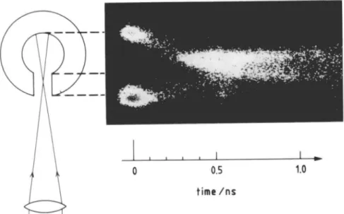
Figure 5 shows the streak camera recording of the X-ray emission of a 300 urn alumi-num cylinder irradiated at ~5-1014 W/cm2 in 80 ps/1054 nm pulses. The picture was taken from the Polaroid negative, because more details can be seen in it than on the print. Due to solarization, strongly exposed regions appear dark again, so that quantitative anal-ysis is not possible. In the figure, vertical direction indicates position, horizontal direc-tion the time; zero time corresponds to the peak of the irradiating laser pulse. It is seen that, at time zero, two bright spots appear, representing the primary plasma (on top) and the plasma on the outside of the entrance slit (below). We note that no emission from the region just inside the slit is observed; this is a consequence of the low irradiance at which the secondary plasma is produced. The primary plasma is then seen to flow radally in-wards until after about 300 ps, the collision with the secondary plasma (invisible up to
1.0
FIGURE 5. Streaked X-ray pinhole image of a 300 fim Al cylinder irradiated at 5 • 1014 W/cm2 (80 ps/ 1054 nm). Contours at the left show the orientation of the cylinder.
this point) results in a pileup of plasma near the cylinder axis, where expansion energy is dissipated into thermal energy. This manifests itself by enhanced X-ray emission. The duration of this emission (almost one nanosecond) is very long compared to the laser pulse duration, implying that the plasma conditions are varying very slowly during this phase. Enhanced X-ray emission is also observed in the entrance slit region after ~600 ps. We interpret this as some fraction of the primary plasma having penetrated the first region of collision (with plasma ablated from the inner edges of the slit) and colliding with plasma within the entrance slit.
An extended view of a typical space-resolved aluminum .K-shell spectrum obtained with the time-integrating crystal spectrometer is shown in figure 6a. The He-like resonance line, Heo, with its satellites, Si and S2, as well as the intercombination line, IC, can be clearly
distinguished. The three emitting zones represent the primary plasma (1), the plasma on the outer surface of the cylinder (2), and the region of plasma collision (3), respectively. Figure 6b shows microdensitometer traces of the complete .K-shell spectra of the zones (1) and (3). As described in more detail in (Weber et al. 1988), several ratios of line inten-sities were used to obtain time-averaged values of the deninten-sities and temperatures inside the cylinders. Density values were deduced from the S1/Hea, Ha/Hea, and IC/Hea line
ratios, while the Wa/Hta ratio was used for temperature determination. As shown in fig-ure 6c, the different line ratios yield an average primary plasma electron density between 1019 and 1020 cm"3. The density in the region of plasma collision is systematically lower by about a factor of two for all shots. A value of 450 eV ± 30 eV is found for the average temperature of the primary plasma, while an average temperature of 350 eV is obtained, with the same error bar, in the region of plasma collision.
4. Hydrodynamic code calculations
An Eulerian code was used to solve the conservation equations for mass and momen-tum for an isothermal plasma. In cylindrical geometry
( 1 )
(3)
( a )
( b )
FIGURE 6. (a) Space resolved spectra of Al XII resonance line with emission from the primary plasma (1), the outer surface (2), and the region of plasma stagnation (3); (b) microdensitometer traces of the complete K-shell spectra of regions (1) and (3). {Continued on facing page.)
H
a/He
aH
a/ H e
a(opt. thick)
Si / H e
aH
a/ H e
aIC / H e
aCOLLIDING
I
PLASMA
r 4 '• 1•
i i ••
icm
102 0^ 1 0
1 9 101 1 "3 (c)\
on
1
00FIGURE 6. (c) Space-resolved, time-averaged values for temperature and density inside the 300 Al cavity, as obtained from line intensity ratios of (b).
a
-r.nate b dt i a . x A ~ T- (rnevp) = 0 r or a ZTe d r nemt dr (1) (2)where ne{r,t), Te(t), Z(t), m, and vp{r,t) are the electron density, electron temperature, mean ionization state, ion mass, and plasma expansion velocity, respectively. The tem-perature was increased according to
(3)
where IL(t) is the temporal profile of the (Gaussian) laser pulse and A is the fraction of laser energy absorbed by the plasma. In this form, A serves as a fit parameter which determines the peak plasma temperature, Tp, reached upon irradiation. The time-depen-dent ionisation equations were solved to yield Z(t). Collisional ionisation and radiative recombination rates were taken from McWhirter (1965). The initial electron density scale-length was set at L = 1 ^m.
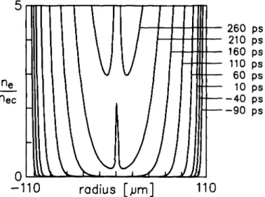
Figure 7 shows the calculated plasma electron density contours at 50 ps intervals for a 220 /an diameter Cu microtube and Tp = 400 eV. Clearly, the early phase, up to -200 ps after the peak of the laser pulse, is characterized by a concave density profile. After this, the inward motion of the plasma ablated at the wall is seen to result in a pile-up of plasma at the center of the tube. If we take the time at which the electron density is greater than the 2w critical value everywhere in the tube as a measure for the time of plasma collision, we obtain a value of ~270 ps. This compares reasonably well with the value of -300 ps deduced from the experimental data in figures 3 and 5.
A final point to note from the code results displayed in figure 7 is that the electron density profile remains virtually unchanged for most of its motion toward the center of the cylinder. This is consistent with the fact that no perturbation of fringes is observed in the interferograms (see figure 2) until late in time (r > 100 ps).
5. Conclusions
Laser irradiation of cylindrical cavities through an axial slit has been investigated with respect to its potential for providing favourable conditions in X-ray laser experiments. It was shown that indirect plasma ablation from the cavity wall is predominantly due to laser light reflected from the primary spot in the case of short pulse, long wavelength,
-110 radius [jum]
110
FIGURE 7. Calculated plasma electron density contours at 50 ps intervals for a 220 jtm Cu microtube and Tp = 400 eV.
high irradiance conditions. Short wavelength irradiation is expected to alter this situation in favor of energy redistribution by soft x-radiation.
The symmetry of the radial plasma evolution may be improved in a number of ways. Multiple longitudinal slits will increase the area of primary irradiation. High energy, long wavelength pulses of a few picoseconds duration may improve the redistribution of laser light in the cavity due to increased plasma reflectivity. Off-center incidence of the irradi-ating laser beam will reduce the substantial fraction of reflected light lost through the slit. The present experiments have shown that the creation of a confined, radially sym-metric, waveguiding plasma may be feasible.
One may speculate about a possible X-ray laser in such a cavity. The rapid cooling required in a recombination scheme, for example, may prove difficult to achieve in this closed geometry, unless additional cooling mechanisms such as radiation and/or conduc-tion cooling are exploited (Milchberg et al. 1985). In this scheme, populaconduc-tion inversion should be attained while the density profile is still concave, i.e., before the collision of the primary and secondary plasmas. A collisional excitation laser scheme could perhaps work during the long duration stagnation phase which would also be appropriate for multi-pass amplification. Due to the density hump at the center the refractive index profile will be less favourable to wave-guiding during this phase. However, this region of increased density is likely also to be a region of increased gain, so that additional benefits from gain-guiding (Kogelnik 1965) could be exploited there.
Acknowledgment
This work was supported in part by the Swiss National Science Foundation.
REFERENCES
BALMER, J. E. & WEBER, R. 1988 Helv. Phys. Ada 61, 132.
BENATTAR, R., POPOVICS, C. & SIGEL, R. 1979 Rev. Sci. Instrum. 50, 1583. CUNNINGHAM, P. F. et al. 1988 Opt. Commun. 68, 412.
GARBAN-LABAUNE, C , et al. 1982 Phys. Rev. Lett. 48, 1018. HAGELSTEIN P. L. 1983 Plasma Physics 25, 1345.
JACOBY, D. et al. 1982 J. Phys. B 15, 3557.
JAEGLE, P. et al. 1986 Europhys. Lett. 1, 555.
KOGELNIK, H. 1965 Appl. Opt. 4, 1562.
LONDON, R. A. 1988 Phys. Fluids 31, 184. LUNNEY, J. G. 1986 Appl. Phys. Lett. 48, 891. MATTHEWS, D. L. et al. 1985 Phys. Rev. Lett. 54, 110.
MCWHIRTER, R. W. P. 1965 Plasma Diagnostic Techniques, R. H. Huddlestone and S. L. Leonard eds. (Academic Press, New York), p. 201.
MILCHBERG, H. et al. 1985 Appl. Phys. Lett. 47, 1151. MORA, P. 1982 Phys. Fluids 25, 1051.
ROSEN, M. D. & HAGELSTEIN, P. L. 1986 Lawrence Livermore National Laboratory Report UCRL-94412.
SEELY, J. F. et al. 1985 Opt. Commun. 54, 289. SUCKEWER, S. et al. 1985 Phys. Rev. Lett. 55, 1753.