HAL Id: tel-02176911
https://hal.archives-ouvertes.fr/tel-02176911
Submitted on 8 Jul 2019HAL is a multi-disciplinary open access archive for the deposit and dissemination of sci-entific research documents, whether they are pub-lished or not. The documents may come from teaching and research institutions in France or abroad, or from public or private research centers.
L’archive ouverte pluridisciplinaire HAL, est destinée au dépôt et à la diffusion de documents scientifiques de niveau recherche, publiés ou non, émanant des établissements d’enseignement et de recherche français ou étrangers, des laboratoires publics ou privés.
Oxidation protection of carbon/carbon composites and
non- destructive characterization methodology
development
Jiaping Zhang
To cite this version:
Jiaping Zhang. Oxidation protection of carbon/carbon composites and non- destructive character-ization methodology development. Material chemistry. Sorbonne Université, 2019. English. �tel-02176911�
Sorbonne Université
Ecole doctorale
L'ECOLE DOCTORALE DE CHIMIE PHYSIQUE ET DE
CHIMIE ANALYTIQUE DE PARIS CENTRE (ED 388)
Oxidation protection of carbon/carbon composites and
non-destructive characterization methodology development
Par [Jiaping ZHANG]
Thèse de doctorat de Chimie Physique et Chimie Analytique
Dirigée par [Philippe JONNARD et Qiangang FU]
Présentée et soutenue publiquement le [28 June 2019] Devant un jury composé de :
M. Zhanshan WANG Professeur Tongji University (Rapporteur) M. Fei MA Professeur Xi'an Jiaotong University (Rapporteur) M. Ahmed NAITABDI Maître de Conférences Sorbonne Université (Examinateur)
Mme.Xiaoli FAN Professeur
Northwestern
Polytechnical University (Examinatrice) M. Philippe JONNARD Directeur de recherche Sorbonne Université (Directeur de thèse)
M. Qiangang FU Professeur Northwestern
1
Acknowledgements
This thesis presents the work I have done in Northwestern Polytechnical University (NWPU) and Sorbonne Université (SU). Here I would like to express my sincere gratitude to my supervisors, Dr. Philippe Jonnard and Dr. Qiangang Fu, for not only their immense knowledge and sharp insights to research, but also enthusiastic supports and encouragements. Specially, I owe my thanks to Dr. Fu for encouraging me to expand my horizon by studying abroad, and to Dr. Jonnard for recruiting me and making possible a wonderful research experience of me in Paris. They teach me the ability to perform independent research. I am very happy and lucky to work with them.
I would like to thank Dr. Karine Le Guen from the team for her valuable advices in revising the thesis and the paper. She always corrects carefully what I write and gives useful comments.
Special thanks to Dr. Alain Dubois for all his warm help from scholarship application to administrative procedures in SU. I am also very grateful for his help in my daily life.
I would like to give my thanks to all the jury members, Dr. Ahmed Naitabdi, Dr. Zhanshan Wang, Dr. Fei Ma and Dr. Xiaoli Fan, for accepting the invitation of evaluating my work.
I would like to thank Ian Vickridge and Didier Schmaus of Institut des NanoSciences de Paris (INSP) for allowing me to work on the SAFIR platform. Thanks also to them for the useful discussions in finishing the project.
Thanks for the financial supports provided by the Erasmus+ mobility scholarship and the China Scholarship Council -SU doctoral program.
I would like to thank all my friends and colleagues in our lab: Christopher, Aladine, Meiyi, Mostafa, Hang, Athony, Atoine, Marie, Sevan, Xuan, Lucia, etc.
I would like to thank my family: they support me all the time until finishing my Ph.D.
Jiaping
3
Contents
Acknowledgements ... 1 Contents ... 3 Chapter 1: Introduction ... 5 1.1 Carbon/carbon composites ... 51.2 Application of carbon/carbon composites ... 6
1.3 Coating technology ... 7
1.4 Matrix modification ... 10
1.5 Purpose of this study ... 11
Chapter 2: Experimental methods ... 14
2.1 Carbon/carbon composites ... 14
2.2 Experimental apparatus ... 15
2.3 Sample fabrication ... 16
2.3.1 Blasting treatment of C/C composites to construct a porous surface ... 16
2.3.2 Coating preparation on blasting-treated C/C composites ... 16
2.3.3 Thin film waveguides preparation on Si substrate ... 19
2.3.4 HfB2 and HfB2-SiC modified C/C composites ... 20
2.4 Characterization ... 22
2.4.1 Ablation test ... 22
2.4.2 Adhesive strength test ... 24
2.4.3 PIXE-Kossel experiment ... 24
2.4.4 X-ray reflectivity measurement ... 26
2.4.5 Microstructure and phase composition ... 26
2.4.6 Thermophysical analysis ... 26
Chapter 3: The effects of C/C blasting treatment ... 27
3.1 Introduction ... 27
3.2 Surface modification of C/C via blasting treatment ... 27
3.3 Blasting treatment on the cyclic ablation performance of Si-Mo-Cr coating ... 30
3.4 Blasting treatment combined with SiC nanowires to enhance the cyclic ablation performance of Si-Mo-Cr coating ... 35
3.4.1 Microstructure and cyclic ablation test ... 35
3.4.2 Ablation mechanism ... 38
4
Chapter 4: The effects of C/C blasting treatment and modifying SiC coating with SiC/HfC
(ZrB2) ... 42
4.1 Introduction ... 42
4.2 Blasting treatment and modifying SiC coating with SiC/HfC additive ... 42
4.2.1 Microstructure and cyclic ablation test ... 42
4.2.2 Ablation mechanism ... 46
4.3 Blasting treatment and modifying SiC coating with SiC/ZrB2 additive ... 47
4.4 Conclusions ... 52
Chapter 5: Develop a non-destructive characterization method for multilayer ceramic coating ... 53
5.1 Introduction ... 53
5.2 Particle-induced X-ray emissions (PIXE) ... 53
5.3 Kossel interferences ... 54
5.4 X-ray waveguides ... 55
5.5 PIXE-Kossel to study thin film waveguides ... 57
5.5.1 Design of the thin film waveguides ... 57
5.5.2 Results and discussion ... 58
5.6 Design and simulation of the HfC/SiC/HfC multilayers ... 70
5.7 Conclusions ... 71
Chapter 6: HfB2 and HfB2-SiC modified C/C composites ... 72
6.1 HfB2 modified C/C composites ... 72
6.1.1 Introduction ... 72
6.1.2 Microstructure and ablation test ... 72
6.1.3 Oxidation and ablation mechanism ... 76
6.2 HfB2-SiC modified C/C composites ... 78
6.2.1 Introduction ... 78
6.2.2 Microstructure and ablation test ... 78
6.2.3 Ablation mechanism ... 87
6.3 Conclusions ... 89
Chapter 7: Conclusion and Perspectives ... 91
Annex ... 94
5
Chapter 1: Introduction
1.1 Carbon/carbon composites
Carbon can be considered as an excellent high temperature material. It can form many allotropes. Among them, diamond (carbon atoms bonded in a tetrahedral lattice arrangement) and graphite (carbon atoms bonded in sheets of a hexagonal lattice) are the two most representative ones. Compared with traditional alloys (Ni-based or Nb-based alloys), graphite has no melting point and its sublimation temperature is up to 3620°C [1]. Based on these unique properties, graphite is suitable for use in thermal protection systems at high temperature. Unfortunately, its poor mechanical properties limit its applications. To overcome the obstacles, carbon/carbon (C/C) composites were developed. C/C composites, consist of carbon fibers reinforcement embedded in a carbonaceous matrix, as shown in Figure 1-1. It could combine the good mechanical performances of the carbon fibers and the excellent high temperature properties of the carbon matrix.
Figure 1-1. Schematic illustration (a) and microstructure (b) of C/C composites. The preparation process of C/C composites is mainly composed of two steps: manufacturing carbon fiber reinforcements and carbon matrix densification. Polyacrylonitrile (PAN)-based and pitch-based carbon fibers are the two typical ones used in carbon reinforcements [2, 3]. Fibers are usually woven in appropriate directions to tailor specific properties [4, 5]. According to the structure differences, the carbon fiber reinforcements can be divided into stacked non-woven layers, needled carbon fiber felts and carbon fiber textiles. For the densification process, chemical vapor infiltration (CVI) and liquid impregnation and
(a)
Fiber Carbon matrix
6
carbonization are the two common methods, which could fill the pores in the carbon fiber reinforcements. Hydrocarbon gases are used as the precursor of CVI. Because of its easy supply and good diffusion rate in carbon fibers reinforcement, methane is the most common used gas in this process [2]. At temperatures of 1000-1400°C, methane could convert into a carbonaceous solid medium (called as pyrocarbon) according to the following reaction (1-1), which could fill the pores of the fiber reinforcements.
(1-1)
As for the liquid impregnation and carbonization, the fiber preform is firstly impregnated into a resin (or pitch) and then carbonized at high temperatures for several cycles to reduce its porosity. Phenolic resin is commonly used owing to its low price and relatively higher yield of carbon during decomposition at high temperature [3].
1.2 Application of carbon/carbon composites
C/C composites possess many unique properties, such as low-density (< 2.0 g/cm3), high
specific strength/modulus, low coefficient of thermal expansion, good friction property, excellent thermal shock resistance and so on. Figure 1-2 displays the high-temperature mechanical properties of different materials. Compared with other materials, C/C composites have higher retention of mechanical properties at high temperatures, which ensure them to be the promising candidates for the fabrication of thermal-structural components at extreme temperatures [2-7]. So C/C composites have been used as the structural materials in vehicle heat shields, rocket nozzles and aircraft brakes. Additionally, properties such as biocompatibility, chemical inertness and good mechanical property also ensure them to be used in medicine and industry.
Figure 1-2. High-temperature mechanical properties of various materials, specific fast-rupture strength as a function of the temperature of various metals and composites [8].
7
However, there exists fiber/matrix interface, micro-pores, micro-cracks, crystal defects, residual stress and impurity particles in C/C [2, 3]. They could act as the active pots of oxidation. The oxidation reaction can be performed according to the following reaction:
(1-2)
The reaction has a large driving force because of its negative value of Gibbs free energy change. In actual environment, the oxidation rate of C/C is complicated because it is determined not by the chemical reaction itself, but also by the transport of the gaseous species. In generally, at lower temperatures (below 600-800°C), oxidation is controlled by the reaction of oxygen with active sites on the carbon surface. At higher temperatures, the oxidation rate is determined by the diffusion of oxygen through the boundary layer at the C/C surface. Compared with oxidation (usually performed in static air at high temperatures) [6, 9, 10], ablation represents the phenomenon that materials are subjected to thermo-mechanical, thermo-chemical and thermo-physical erosions from a heat source at high temperature, pressure and velocity. For C/C, during ablation, appreciable amounts of the heat flux are converted to an outward mass flux through the oxidation consumption, leading to a mass loss. So, although the composites could meet the mechanical requirements, rapid oxidation of carbon fiber and carbon matrix in an oxidizing environment severely limits their wide applications. Coating technology and carbon matrix modification are regarded as the two effective ways to enhance the oxidation/ablation resistance of C/C composites.
1.3 Coating technology
The aim of coating technology is to isolate C/C from the oxidizing environments. The requirements for a protective coating system are shown in Figure 1-3, which are listed as follow:
(1) chemical compatibility with the C/C substrate, especially to prevent outward diffusion of carbon and avoid the reaction of the substrate and the coating.
(2) thermo-physical compatibility, mainly representing the thermal expansion coefficient match.
(3) diffusion stability when in contact with chemical compounds.
(5) low oxygen permeability to prevent the inward diffusion of oxidized species. (6) low volatility to prevent excessive ablation in high-velocity gas streams.
8
Volatility
Coating
Carbon out
Chemical and Mechanical Compatibility
Adhesivenes s
C/C Oxygen in
Figure 1-3. Requirements for the coating on the surface of C/C composites [2, 11]. Many methods have been performed to prepare protective coating on the surface of C/C
composites. Si-based ceramics (such as SiC and MoSi2) and ultra-high-temperature ceramics
(UHTCs) or a combination of them are commonly used as the coating materials. The selection of Si-based ceramics can be mainly attributed to the self-sealing performance of the formed
glassy SiO2 (the oxidation product of Si-based ceramics) at high temperature. UHTCs
representing the carbides, nitrides and borides of refractory metals, are used because of their high-melting points, good mechanical properties, oxidation performances and ablation
resistances [12-16]. Table 1-1 shows the basic physical properties of C/C, SiC, MoSi2 and
some typical UHTCs. Many methods have been developed to fabricate the protective coating on the surface of C/C. The most commonly used ones are pack cementation, chemical vapor deposition and plasma spraying. Each method is briefly described, as follow.
Table 1-1. Properties of SiC, MoSi2 and some typical UHTCs [17-20]. CTE is the coefficient
of thermal expansion.
Property C/C SiC MoSi2 HfC ZrC TaC HfB2 ZrB2
Density (g/cm3) 1.75 3.2 6.26 12.7 6.6 14.5 11.2 6.10
Melting point (°C) - 2700 2030 3890 3540 3880 3380 3245
CTE (10-6/K) 1-2 4.3 8.25 6.8 7.3 6.6 6.3 5.9
(1) Pack cementation
During pack cementation, C/C composites are immersed into the mixed powders of the coating materials and then heat-treated at high temperature. The molten coating materials will infiltrate into C/C or react with carbon matrix to form the ceramic coatings. Ren et al. [21] adopted this method to prepare SiC coating on the surface of C/C, as shown in Figure 1-4. The prepared coating showed a good adhesive strength with the C/C substrate.
9
Figure 1-4. Schematic diagram of the SiC coating prepared by pack cementation [21]. (2) Chemical vapor deposition (CVD)
CVD is a deposition method used to produce high quality, high-performance solid materials. The process mainly consists of the dissociation and/or chemical reactions of gaseous reactants and the deposition of a stable solid product. HfC coating was successfully prepared by this method [22], as shown in Figure 1-5. The prepared coating shows a dense structure. However, due to the low deposition rates, the processing times of CVD are long, resulting in the increase of manufacturing cost.
Figure 1-5. Cross-sectional image of a HfC coating obtained by CVD [22]. (3) Plasma spray
Plasma spray technology is a simple way to prepare refractory coatings with high melting points. Diverse materials, such as metal and ceramics, can be applied as the spray materials, as shown in Figure 1-6. Material in the form of powder is injected into a very high temperature plasma flame, where it is rapidly heated and accelerated to a high velocity. The hot material impacts on the substrate surface and rapidly cools forming a coating. However,
10
various defects, such as high porosity, poor bonding strength, high surface roughness and lamellar stacking characteristics, could also form. So subsequent processing needs to be performed to eliminate the above defects.
Figure 1-6. Schematic of a plasma spray process [23].
1.4 Matrix modification
Another promising approach is to modify C/C composites with UHTCs or Si-based ceramics. Instead of fabricating the protective coating on the surface of C/C, the aim of matrix modification is to introduce the ceramics into the C/C matrix, which could couple the excellent oxidation/ablation resistance of UHTCs or Si-based ceramics with the good fracture toughness of C/C [24, 25]. Processing methods have been carried out on the fabrication of C/C-UHTCs, such as chemical liquid-vapor deposition [26], chemical vapor infiltration [27], precursor infiltration and pyrolysis [28], carbo-thermal reduction reaction [14], slurry infiltration [24, 29, 30], hot pressing [31], microwave hydrothermal [32] and reactive melt infiltration [33]. In addition, two or more methods (see above) are often combined to facilitate the preparation of the modified C/C composites. Among these preparation methods, chemical vapor infiltration, precursor infiltration and pyrolysis, reactive melt infiltration and slurry infiltration are often used, which are described as follow.
(1) Chemical vapor infiltration (CVI)
This process involves complex physico-chemical phenomena, such as the transport of precursors, carriers, and by-product gases in the reactor [34]. The prepared composite possesses well-controlled composition and microstructure, good mechanical and anti-ablation
properties. By using TaCl5-CH4-H2-Ar, HfCl4-TaCl5-CH4-H2-Ar and HfCl4-TaCl4-CH4-H2-Ar
as the gas sources, C/HfC, C/TaC and C/HfC/TaC composites were fabricated [27]. Although this method could prepare high-quality materials, it is expensive and time-consuming.
11 (2) Precursor infiltration and pyrolysis
Precursor infiltration and pyrolysis (PIP) is the method used in the preparation of ceramic matrix composites, which comprises an infiltration of a low viscosity polymer into the fiber preforms followed by pyrolysis: heating the polymer precursor in the absence of oxygen when it decomposes and converts into a ceramic. It could introduce variable kinds of ceramics and benefit for achieving near net shape manufacturing. Based on this method,
C/C-HfC [35], C/C-ZrB2-SiC [36] and C/C-ZrC-SiC [37] were successfully prepared. The major
disadvantage of PIP is time-consuming, and that matrix is easy to shrink during pyrolysis, which may result in formation of cracks and pores.
(3) Reactive melt infiltration
Reactive melt infiltration (RMI) is used to introduce carbide or boride ceramics into composites through the reaction between molten metal mixtures and C/C composites. With respect to CVI and PIP, it is a cost-effective and time-saving method. For example, Wang et
al. used Si0.87Zr0.13 alloy as the raw material. When heat-treated at high temperatures, the
molten Si0.87Zr0.13 alloy was infiltrated into the C/C to form C/C–SiC–ZrC composites [38].
But the inevitable reactions between the molten mixture and carbon fibers resulted in the mechanical property degradation.
(4) Slurry infiltration
In slurry infiltration (SI), the precursor is a slurry which could infiltrate into fiber preforms. It is also convenient to introduce different ceramics into C/C according to
requirements. Sun et al. used this method to introduce ZrSiO4 into C/C [39]. However, the
agglomeration of ceramics particles usually blocks the `pores of fiber preforms and then makes it more difficult for the subsequent densification.
1.5 Purpose of this study
As discussed above, coating technology and matrix modification are the two efficient methods to enhance the oxidation and ablation performances of C/C. They are also the focuses of our work. The novelty of our study is described as follow and compared to the reported literature.
For the coating technology, up to now, many different types of protective coatings, such
as Si-Mo-Cr [40], mullite/SiC [10], AlPO4/SiC [41], BN/SiC/Si3N4-ZrO2-SiO2 [42], ZrB2
-SiC/SiC [43], have been developed. However, the CTE (coefficient of thermal expansion) mismatch (see Table 1-1) between the coating and C/C substrate easily results in the
12
generation of cracks during high-low temperature cycles, which would provide the entrance channels for oxygen [44]. Evans et al. [45] have discussed the interface degradation mechanism, indicating that the large CTE difference will lead to the increase of internal stress, resulting in the degradation. As a result, the CTE mismatch is the key factor that results in the coating performance degradation.
To relieve the CTE mismatch between the coating and substrate, many attempts have been performed. The introduction of a second phase into the coating is the most widely adopted strategy to tackle this problem so as to improve the toughness of the coating considerably, where carbon nanotubes (CNTs) and SiC nanowires have been used [46, 47]. The introduction of a second phase proves to be ineffective for the improvement of the
coating/substrate interface. Feng et al. [48] use low-density C/C composites (1.2 g/cm3) to
make use of their porous structures, which could provide the diffusion paths to the coating raw materials and then contribute to the increase coating/substrate interfaces. These interfaces could promote the oxidation performance of the produced coating. However, to ensure the thermal-structural components with favorable mechanical performances, C/C composites with
enough density (>1.7 g/cm3) and low porosity are required. Thus, this method is difficult to
adopt in practical applications. In light of this problem, as an alternative method, pre-oxidation treatment of C/C was developed to construct a preferential interlocking transition coating/substrate interface [49]. The results showed that the oxidation treated region of C/C composites was difficult to control, and the treatment time was relatively longer, resulting in the inevitable damage of the mechanical performance of C/C [50].
As a result, finding a simpler, faster and more efficient way to construct an interlocking coating/substrate interface on high-density C/C (in the premise of minimum mechanical property loss) is becoming particularly important. So, in this study, blasting treatment of C/C is proposed. In addition, in actual environment, a non-destructive method is very important for the coating structure characterization and its service reliability evaluation. So in this thesis, Kossel interferences of proton-induced X-ray emission combined with X-ray reflectivity measurement, as a novel characterization method, is developed.
For the matrix modification, based on the above fabrication methods (discussed in
section 1.4), a series of composites, such as C/C-HfC [35], C/C-ZrC-ZrB2-SiC [36],
C/C-ZrC-SiC [51-53], and C/C-ZrB2-SiC [54], have been successively developed. It is evident that
although a considerable amount of studies have been performed on the development of C/C-UHTCs composites, much of them are focused on HfC and Zr-based ceramics, with little
13
point (3250°C) and good oxidation/ablation resistance [56]. When the boron oxide layer (the
oxidation product of HfB2) is sufficiently fluid, it could also cover the surface and act as an
efficient barrier to restrict the inward diffusion of oxygen. HfB2 is thus a promising candidate
to improve the ablation properties of C/C composites.
A. Paul et al. fabricated C/C-HfB2 by slurry infiltration [24, 29, 30]. However, the
agglomeration of the HfB2 particles easily blocked the pores in the outer layer of the C/C
preforms and then made it difficult for the successive densification. To ensure the service
reliability of C/C-HfB2 composites, it is of great significance to resolve the problem of
agglomeration and find out the valid dispersion method of HfB2. So in this study, PIP is
adopted to introduce HfB2 into C/C matrix. Compared with slurry infiltration, this method
possesses a larger infiltration depth, which can be expected to improve the uniformity of HfB2
and realize the net shape manufacturing.
According to the discussion above, the main contents of the PhD work are listed as follow:
(1) Effect of blasting treatment of the C/C composites on microstructure, adhesive strength, oxidation/ablation performance of the ceramic coating (chapter 3).
(2) C/C blasting treatment combined with a second phase introduction to enhance the oxidation/ablation performances of the ceramic coating (chapters 3 and 4).
(3) Feasibility of Kossel interferences of proton-induced ray emissions combined with X-ray reflectivity, as a novel non-destructive characterization method, where X-X-ray planar waveguides are designed (chapter 5).
(4) Preparation of HfB2 and HfB2-SiC modified C/C composites. Effect of HfB2 and HfB2
14
Chapter 2: Experimental methods
In this chapter, we will give a detailed description of the raw materials, fabrication apparatus and characterization methods used in this thesis.
2.1 Carbon/carbon composites
2D carbon fiber felt was used as the reinforcement for C/C composites, as shown in Figure 2-1. The preform is made up of 90° weftless ply, short-cut fibre web and 0° weftless ply (see Figure 2-1 (a)). They are alternatively stacked with a needle punching technique (Figure 2-1 (b-c)). The fiber volume content of the preform is about 20–25%. C/C composites are prepared through the densification of the carbon fiber preform by thermal gradient
chemical vapor infiltration (TCVI). During this process, CH4 is used as the precursor with a
flow rate of 4-8 L/min. The deposition time, temperature and pressure were 100-120 h,
1050-1150oC and 5-10 kPa, respectively. The final density of the C/C composites was about
1.69-1.75g/cm3. Morphology and phase composition of the C/C are shown in Figure 2-2. They
consist of a single carbon element (Figure 2-2 (b)), and carbon fiber is surrounded by pyrolytic carbon matrix (Figure 2-2 (a)).
Figure 2-1. Schematic illustration of needled integral felts including a needling process: (a) position of weftless ply and short-cut fibre web; (b) detailed view of a Z-fibre bundle generated during the needling process; and (c) needling process [57].
15
Figure 2-2. Microstructure (a) and phase composition (b) of the C/C composites.
2.2 Experimental apparatus
The experimental apparatuses, including the coating/film preparation and sample analysis, are listed as follow.
(1) High-temperature heat treated furnace: the maximum temperature is 2300 °C.
(2) Cutting machine: MODEL150.
(3) Ball mill: PM-4L, rotation speed <600 rpm.
(4) Supersonic cleaner: KQ-100A.
(5) Drying oven: 101A-2, the maximum temperature is 200 °C.
(6) Analytical balance: TG328B, accuracy ±0.0001 g.
(7) Universal mechanical test machine: CMT5304-30 kN.
(8) Thermal expansion test: DIL402C and DIL402E Dilatometer.
(9) Infrared radiation thermometer: Raytek MR1SCSF, accuracy of 0.75%.
(10) X-ray diffraction (XRD): Philips X'Pert MPD diffractometer.
(11) Thermal analysis: Mettler Toledo Star TGA/SDTA 851.
(12) Confocal laser scanning microscope : C130, Lasertec Corp., Yokohama, Japan.
(13) Scanning electron microscopy (SEM): VEGA 755136XM.
(14) Thermal cycling and ablation test: OA-Ш oxyacetylene ablation machine.
(15) Film deposition: magnetron sputtering.
(16) Système d’Analyse par Faisceaux d’Ions Rapides (analysis system with high speed
ion beams) platform in Sorbonne University.
(17) ANDOR iKon-M energy dispersive CCD camera.
(b)
Fiber Matrix
16
2.3 Sample fabrication
2.3.1 Blasting treatment of C/C composites to construct a porous surface
Cylinder specimens (Ø10 mm × 10 mm) used as substrates were cut from the prepared C/C composites (described in section 2.1). They were hand-abraded with 100 and 400 grit SiC papers in turn, then cleaned ultrasonically with ethanol and dried at about 80°C for 2 h. A porous surface of C/C was achieved rapidly through blasting treatment using oxyacetylene torch. The flame was vertical to the C/C, as shown in Figure 2-3. In our study, C/C was
treated in three different heat fluxes (2.38, 3.2 and 4.18 MW/m2) [58]. The parameters are
listed in Table 2-1. During blasting treatment, the gas pressures of O2 and C2H2 were kept
constant, and the heat flux of the oxyacetylene torch was adjusted through changing the flow
ratio of O2 and C2H2. The treatment time was 20-30 s.
Figure 2-3. Schematic illustration of blasting treatment of C/C using oxyacetylene torch. Table 2-1. Blasting treatment parameters of the oxyacetylene torch [58].
C2H2 (m3/h) O2 (m3/h) Heat fluxes (MW/m2)
0.65 0.88 2.38
0.83 1.12 3.20
1.12 1.51 4.18
2.3.2 Coating preparation on blasting-treated C/C composites
(1) SiC coating
To investigate the effect of blasting treatment, SiC coating was prepared on the treated C/C (obtained in section 2.3.1) by pressure-less reaction sintering. Powder compositions were
as follows: 65-80 wt.% Si (300 mesh), 10-25 wt.% graphite (325 mesh) and 5-15 wt.% Al2O3
(300 mesh). The role of Al2O3 was used to increase the rate of diffusing reaction at high
temperature. The powders were mixed together in an agate vial and stirred for 8 h in a ball mill (PM-4L) with the speed of 500 rpm. Then the mixed powders and the treated C/C
17
specimens were put in a graphite crucible and heated to 1750-2100°C and held at that temperature for 1-3 h in argon atmosphere.
(2) Si-Mo-Cr coating
Figure 2-4 shows the process of blasting treatment and preparation of Si-Mo-Cr coating. Firstly, blasting treatment of C/C composites was conducted (described in section 2.3.1). Then, Si-Mo-Cr coating was prepared by pressure-less reactive sintering. Powder
compositions were as follows: 45-60 wt.% Si (300 mesh), 25-30 wt.% MoSi2 (200 mesh),
5-15 wt.% Cr (200 mesh) and 8-5-15 wt.% graphite (200 mesh). The powder mixtures and C/C specimens were mixed together and in turn put in a graphite crucible, and then heat treated at 1750-2100°C for 1-3 h in argon atmosphere.
Figure 2-4. Schematic illustration of blasting treatment of C/C and preparation of the Si-Mo-Cr coating.
(3) SiC nanowires toughened Si-Mo-Cr coating
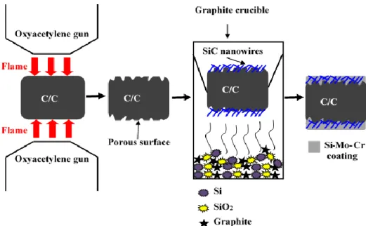
Figure 2-5 shows the schematic illustration of blasting treatment of C/C, in situ grown SiC nanowires and preparation of Si-Mo-Cr coating. It was divided into three steps. The first step was to construct a porous surface on C/C via blasting treatment (details are in section 2.3.1). In the second step, in situ growth of SiC nanowires was prepared on the surface of the
treated C/C composites by chemical vapor deposition (CVD). Mixed powders of SiO2, Si and
graphite were placed on the bottom of a crucible. Then, the treated C/C composites were placed above the mixed powders and heat treated in an argon atmosphere to form the SiC nanowires. Finally, Si-Mo-Cr coating was prepared by pressure-less reactive sintering (see in Figure 2-4).
18
Figure 2-5. Schematic illustration of C/C blasting treatment, in situ grown SiC nanowires and preparation of Si-Mo-Cr coating.
(4) HfC-SiC coating
The procedure of constructing the porous surface on C/C composites and the preparation of HfC-SiC coating is shown in Figure 2-6.
Figure 2-6. Schematic illustration of C/C blasting treatment and the preparation of HfC-SiC coating.
In the first step, a porous surface was constructed on C/C. Then the HfC-SiC coating was prepared on the pre-treated C/C composites by pressure-less reactive sintering. Powder compositions for pressure-less reactive sintering were as follows: 45-65 wt.% Si (300 mesh), 10-15 wt.% HfC (400 mesh) and 8-30 wt.% graphite (300 mesh). The powders were mixed uniformly in an agate vial after being stirred for 12 h in PM-4L ball mill with a speed of 500
19
rpm. Then, the obtained powder mixtures and the pre-treated C/C specimens were put in a
graphite crucible, which were heated to 1800-2300oC and held for 1-4 h in an argon
atmosphere.
(5) ZrB2-SiC coating
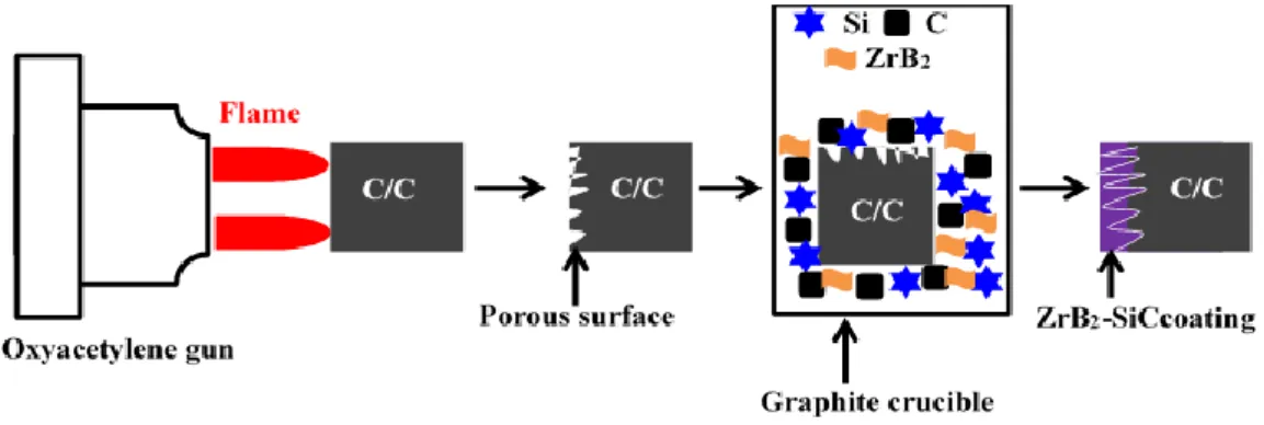
The procedure of constructing the porous surface on C/C and the preparation of ZrB2
-SiC coating is shown in Figure 2-7. The process is the same as that of HfC--SiC coating. ZrB2
-SiC coating was prepared on the pre-treated C/C composites by pressure-less reactive
sintering. Powder composition was as follow: 45-65 wt.% Si (300 mesh), 10-15 wt.% ZrB2
(300 mesh) and 8-30 wt.% graphite (300 mesh).
Figure 2-7. Schematic diagram of C/C blasting treatment and introducing ZrB2 into SiC
coating by pressure-less reactive sintering.
2.3.3 Thin film waveguides preparation on Si substrate
Figure 2-8. Schematic diagram of the designed waveguides.
Three thin films waveguides were designed: Pt(4 nm)/Fe(6 nm)/Pt(10 nm)/Si, Pt(4 nm)/Fe(8 nm)/Pt(10 nm)/Si and Ta(4 nm)/Cr(10 nm)/Pt(12 nm)/Si, as shown in Figure 2-8. The designed thin films were deposited at room temperature on a Si (100) substrate by
Pt (4 nm) ) Fe (6 nm) ) Pt (10 nm) ) Pt (4 nm) ) Fe (8 nm) ) Pt (10 nm) ) Cr (10 nm) ) Pt (12 nm) ) Ta (4 nm) )
20
magnetron sputtering, as shown in Figure 2-9. The power applied on the sputtering targets
was 10 W, the base pressure was 10-8 mbar, and the sputtering gas was argon at the working
pressure of 5×10⁻² mbar. The sputtering rates of Pt, Fe, Cr and Ta were 0.066, 0.024, 0.024
and 0.035 nm/s, respectively, as measured by a quartz microbalance.
Figure 2-9. Experimental setup of the magnetron sputtering.
2.3.4 HfB2 and HfB2-SiC modified C/C composites
(1) Preparation of C/C-HfB2 composites
Precursor infiltration and pyrolysis (PIP) is a common method to introduce ceramics into C/C preforms. It usually consists of two processes: infiltration of a low viscosity precursor
and pyrolysis at high temperature. In our study, C/C-HfB2 was prepared by PIP, as shown in
Figure 2-10. In the first step, the carbon fiber felt (described in section 2.1) was densified to
1.0-1.1 g/cm3 by isothermal chemical vapor infiltration (ICVI) process. The ICVI temperature
and time were set at 1000-1150°C and 30-40 h, respectively. Then HfB2 was introduced into
C/C composites by PIP. Details of PIP are given in Figure 2-11. A solution of organic hafnium boride polymer and xylene was used as the precursor. The obtained low-density C/C composites in the first step were put in an airtight container. The container was evacuated (pressure lower than 6 kPa). Because of the pressure difference inside and outside of the container, the liquid precursor was inhaled and immersed the prepared C/C samples for 1-2 h. Then the samples were dried at 90 -100°C in air for 24 h. After that, the samples were put in a
graphite crucible and held at 1500-1800oC for 1-4 h in argon atmosphere (shown in Figure
2-10). The above process was repeated until the density increased to 1.3-1.4 g/cm3. After that,
the obtained samples were further densified by pyrolysis carbon through TCVI. During this
process, CH4 was used as the carbon source. Finally, the prepared composites were
C/C-21
HfB2 composites was about 1.77-1.84 g/cm3.
Figure 2-10. Schematic illustration of the preparation of C/C-HfB2 composites.
Figure 2-11. Schematic of the vacuum infiltration device [39].
(2) Preparation of C/C-HfB2-SiC composites
The preparation process of C/C-HfB2-SiC composites is similar to that of C/C-HfB2. The
main difference is the sample shape and the PIP precursor. In the first step, the carbon fiber
felt (described in section 2.1) was densified to 1.0-1.1 g/cm3 by ICVI. Then the composites
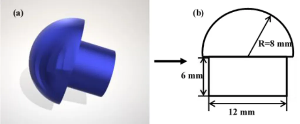
were machined into nose shape to simulate the thermal-structural components used in actual environment, as is shown in Figure 2-12 (a-b). The nose-shaped sample is made up of two parts: a hemisphere (the radius is 8 mm) and a cylinder (the diameter is 12 mm and the height is 6 mm). Then a mixed solution of organic hafnium boride polymer and polycarbosilane was
Pressure indicator
Samples
Precursor Vacuum
22
prepared, which was dispersed in dimethylbenzene with a weight ratio of 1:1. The solution
was used as the precursor to introduce HfB2-SiC into C/C. The final density of the composites
was 1.94-2.03 g/cm3 after ten PIP cycles.
Figure 2-12. Schematic diagram of the prepared nose-shaped C/C-HfB2-SiC composite (a)
and the corresponding dimensions (b).
2.4 Characterization
2.4.1 Ablation test
(1) Single ablation test
Ablation behavior was investigated using oxyacetylene torch. The experiment setup consisted of oxygen and acetylene tanks, an oxyacetylene gun, a control cabinet and a sample stage. The inner diameter of the oxyacetylene gun tip was 2 mm, and the corresponding
distance to the sample was 10 mm. Two different heat fluxes (2.38 and 4.18 MW/m2) were
used. Detailed parameters of the heat flux were described in section 2.3.1. During ablation, surface temperature was measured by a two-color pyrometer (Raytek MR1SCSF, accuracy of 0.75%). The linear and mass ablation rates of the specimens were obtained according to the formula (2-1) and (2-2) 1 2 l d d d R t t (2-1) 1 2 m m m m R t t (2-2)
where Rl is the linear ablation rate; d1, d2 are the thickness of the sample center before and
after ablation; Rm is the mass ablation rate; m1, m2 are the sample mass before and after
ablation; t is the ablation time. The final ablation value is the average of the measurements over three specimens.
23 (2) Cyclic ablation test
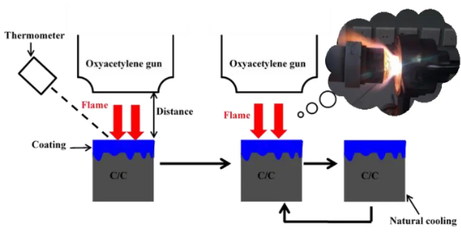
Cyclic ablation was conducted using vertical and parallel oxyacetylene torch, as shown
in Figures 2-13 and 2-14. Surface temperature of the sample was measured by the Raytek
MR1SCSF thermometer. In our study, two cyclic ablation tests (1600oC to room temperature
and 1750oC to room temperature) were performed. Gas fluxes of O2 and C2H2 were 0.88 and
0.65 m3/h. The ablation temperature was controlled through the adjustment of the distance
between the oxyacetylene torch and the sample.
Figure 2-13. Schematic illustration of cyclic ablation test using vertical oxyacetylene torch.
Figure 2-14. The cyclic ablation test using parallel oxyacetylene torch, (a) Schematic illustration of the experimental setup before test, (b) Experimental setup during test, (c) Schematic illustration of (b).
To better study the cyclic ablation performance of the coating, the mass loss per unit area in each thermal cycle was obtained according to the formula (2-3). Detailed descriptions of
24
the cyclic ablation test are as follow. Firstly, the mixture of O2 and C2H2 was ignited, and then
the distance between oxyacetylene gun and the sample was adjusted so as to make the surface
temperature reaching 1600 or 1750oC. Then the cyclic ablation test was carried out. The
ablation time in each cycle was set as 5, 10, 20 s according to the requirement. After that, the oxyacetylene flame went out, and the sample was cooled down naturally before the next thermal cycle.
(2-3)
where ΔW is the mass loss per unit area; m0, m1 are the sample mass before and after cyclic
ablation test, respectively; A is the area of ablation surface. The final mass loss per unit area is the average of the measurements over three specimens.
2.4.2 Adhesive strength test
The adhesive strength between the coating and C/C was measured using adhesive method. A schematic of the test device is shown in Figure 2-15. Cylindrical stainless-steel rods are used as matching parts. Specimens are bonded with the end surface of matching parts by a modified acrylate adhesive. After being positioned for 10–15 min and solidified for 24 h at room temperature, the specimens are measured by a universal test machine (detail given in section 2.2), and the largest force of each specimen is recorded. The adhesive strength (σ) is calculated according to the following formula (2-4):
(2-4)
where F is the largest force recorded by the universal testing machine and S is the cross-sectional area of the coated specimens.
Figure 2-15. Schematic of the testing device used for the adhesive strength.
25
The proton beam we work with is provided by the SAFIR (Système d’Analyse par Faisceaux d’Ions Rapides) platform of Sorbonne University in Paris, France. This research platform is based on a type AN-2000 electrostatic Van de Graaff particle accelerator associated with beamlines and experimental chambers. The principle of the accelerator is to impart kinetic energy to charged particles. The different ionizable gases (H, He, ...) are stored in the upper part of the accelerator. They are ionized by a radiofrequency field of the order of 100 MHz and then magnetically focused in the axis of the extraction channel. The accelerator
is capable of generating ion beam of H+, D+, He+, C+, N+, O+ with a small divergence of 0.5
mrad and an energy up to 2.5 MeV. Spot size of the beam can be adjusted down to 1 mm2.
The plarform could carry out the following tests, Rutherford backscattering spectrometry (RBS), particle induced X-ray emission (PIXE), nuclear reaction analysis (NRA), elastic recoil detection analysis (ERDA) and particle channelization in single crystals. The schematic diagram of our PIXE-Kossel experiment is shown in Figure 2-16.
Figure 2-16. Scheme of the experimental setup for the PIXE-Kossel experiment. A 1.6 MeV proton beam generated by the Van de Graaff accelerator of the SAFIR platform, was incident normal to the sample surface. An ANDOR iKon-M energy dispersive CCD camera equipped with a 1024×1024 sensor array and 13×13 μm pixels, was used to record the generated X-ray emissions. This CCD camera produces an x-ray spectrum for each of its pixels. Each column of pixels corresponds to a detection angle. To facilitate the data acquisition and subsequent data processing, a 4×4 binning is selected to obtain 256×256 pixel
26
images (as shown in Figure 2-16). The angular acceptance of the camera is 2.71°, as determined in [59]. As shown in Figure 2-16, when the proton beam irradiates the sample, we first obtain a picture on the CCD camera, where the intensity of a pixel depends on the total number of x-rays collected in this pixel. After the energy calibration of the spectrum, a region of interest (ROI) is selected around a characteristic line, to obtain a 256×256 filtered spectral image. Then, this image is integrated in the vertical direction so as to obtain a 256 channel scan, representing the intensity of the given line as a function of the detection angle (grazing exit angle θ), i.e. the Kossel curve.
2.4.4 X-ray reflectivity measurement
To know the actual thickness and roughness of the deposited stacks, X-ray reflectivity (XRR) measurement is conducted. XRR is widely employed to study thin films and multilayers. In this study, the XRR measurements were performed at the 0.1542 nm wavelength on a Rigaku five-circle diffractometer. Then with the help of the IMD software [60] and the optical constants of the CXRO [61], the measured XRR curves were fitted to determine the thickness, roughness and density of the various layers.
2.4.5 Microstructure and phase composition
The microstructures and morphologies of the samples are analyzed by scanning electron microscopy, equipped with energy dispersive spectrometry (EDS). The phases are analyzed by X-ray diffraction with a Cu Kα radiation (λ=0.1542 nm) from an x-ray tube operating at 40 kV and 35 mA. With the help of a confocal laser scanning microscope, the average surface roughness (Ra) of C/C before and after blasting operation was measured.
2.4.6 Thermophysical analysis
Thermogravimetric analysis was carried out in air condition by thermal analysis apparatus. Coefficient of thermal expansion (CTE) was measured by a dilatometer (see section 2.2).
27
Chapter 3: The effects of C/C blasting treatment
3.1 Introduction
A preferential interlocking transition layer is beneficial for relieving the CTE mismatch and enhancing the adhesive strength between the coating and the substrate [48, 49, 62]. In this chapter, to efficiently achieve a porous surface of C/C, blasting treatment using oxyacetylene torch is proposed. Because of its good physical and chemical adaptability with the C/C substrate [10, 41, 43, 63-65], SiC and Si-Mo-Cr coatings are then prepared on the surface of C/C to investigate the effect of blasting treatment.
3.2 Surface modification of C/C via blasting treatment
Details of the blasting treatment of C/C are described in chapter 2. In this section, for the convenience of discussion, C/C without pre-blasting treatment is marked as S-0, and C/C
composites with blasting treatment in the heat fluxes of (2.38, 3.2 and 4.18 MW/m2) are noted
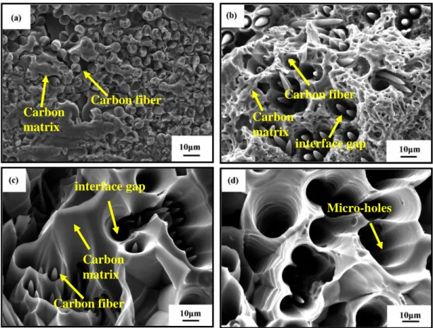
S-1, S-2 and S-3, respectively. Figure 3-1 presents the surface morphologies of C/C composites after blasting treatment, from which a distinct change is observed. On the surface of S-0 (Figure 3-1 (a)), no obvious interface gap is found between the carbon fiber and carbon matrix, and pyrolysis carbon surrounds the circle carbon fibers tightly. As for S-1 (shown in Figure 3-1 (b)), needle-like carbon fibers are observed, indicating the C/C substrate suffered obvious erosion. In addition, interface gaps could be found between carbon matrix and carbon fibers. During blasting treatment, oxidation took place preferentially at the fiber/matrix interface and the oxidizing gas diffused into the substrate gradually, resulting in the formation of needle-like fibers and interface gaps. Figure 3-1 (c) shows the surface morphologies of S-2.
Compared with S-1 (Figure 3-1 (b)), needle-like feature of carbon fibers becomes more
apparent, and the interface gaps between carbon fibers and carbon matrix grow wider and deeper. Compared with the surface morphology of S-1 and S-2 (Figure 3-1 (b-c)), the surface of S-3 suffers more serious erosion and only a little carbon fiber could be observed, indicating that most of the carbon fibers is consumed by the oxyacetylene torch (Figure 3-1 (d)). The interface gaps between carbon fibers and carbon matrix are further enlarged, resulting in the formation of micro-holes. In addition, debonding of the pyrolytic carbon (surrounded the carbon fiber) is also observed on the surface, which can be mainly attributed to the thermal conductivity difference of pyrolytic carbon in radial and axial direction. It has been reported
28
that the radial thermal conductivity of pyrolytic carbon (about 3.5-50 W/(m∙K)) is much lower than that in the fiber axial direction (about 25.6–174W/(m∙K)) [66]. The as-received coarse and porous structure (seen in Figure 3-1 (b-d)) is expected to provide diffusion paths for the coating materials to infiltrate into the C/C substrate and form an inlaid coating/substrate interface.
Figure 3-1. SEM micrograph of the C/C composites after blasting treatment in different heat fluxes using oxyacetylene torch: (a) S-0, (b) S-1, (c) S-2, (d) S-3.
Figure 3-2. Typical surface morphology (a) and XRD pattern (b) of the prepared SiC coating by pressure-less reactive sintering.
Carbon matrix Carbon fiber Carbon matrix interface gap Carbon fiber Micro-holes Carbon matrix interface gap Carbon fiber
29
SiC coating is then prepared on the treated C/C to study the effect of blasting treatment. Surface morphology and phase compositions of the as-prepared SiC coating are shown in Figure 3-2. As seen in Figure 3-2 (a), SiC shows different grain sizes. The main phases of the SiC coating are SiC and Si (see in Figure 3-2 (b)). During pressure-less reactive sintering, SiC is formed by the reaction of Si and C. To ensure the complete consumption of the C, an excess of Si is chosen. The content of Si and SiC could be adjusted through the ratio of Si and C in the powders [67]. As a result, a little amount of Si is detected (seen in Figure 3-2 (b)).
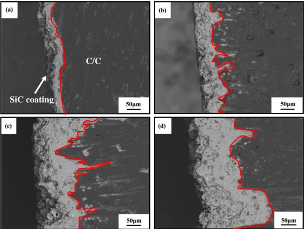
Figure 3-3. Cross-section micrograph of the SiC coated C/C with blasting treatment in different heat fluxes under the oxyacetylene torch: (a) S-0, (b) S-1, (c) S-2, (d) S-3. Figure 3-3 shows the cross-section micrograph of the prepared SiC coating. The interfaces between SiC coating and C/C substrate are emphasized by a red line. From Figure 3-3, significant differences can be found at the coating/substrate interface, and the thickness of the as-received coatings ranges from 50 to about 210 μm. For the coated C/C without blasting treatment (Figure 3-3 (a)), a straight interface structure is formed, and only little amounts of coating materials are infiltrated into the C/C substrate with the coating thickness of 50 μm. Figure 3-3 (b-d) presents the interface structure of the SiC coating with blasting treatment. Compared with the interface structure of S-0 (Figure 3-3 (a)), an inlaid
C/C
30
coating/substrate interface is formed, indicating that the as-received porous and coarse surface (Figure 3-1 (b-d)) produced by blasting treatment is beneficial to form a transition layer. During pressure-less reactive sintering, the fiber/matrix interface gaps (Figure 3-1 (b-d)) provided the diffusion channels for the coating materials into C/C substrate. As for S-1 (Figure 3-3 (b)), it can be found that the amount of coating material infiltrating into the C/C substrate increases with the coating thickness of 80 μm. As for S-2 (Figure 3-3 (c)), the infiltration depth as well as the infiltration amount of coating materials increases, and the coating thickness reaches about 130 μm. With respect to the interface structure in Figure 3-3 (b), an obvious interlock interface is formed. As for S-3 (Figure 3-3 (d)), the infiltration amount of coating materials further increases, resulting in the coating thickness increasing to about 210 μm (Figure 3-3 (d)). The above results indicate that the formed micro-holes (Figure 3-1 (d)) produced by blasting treatment is filled with the coating materials through the flow of liquid Si during pressure-less reactive sintering.
Figure 3-4 reveals the adhesive strengths of the SiC coated C/C composites, from which it can be found that blasting treatment can improve the coating/substrate adhesive strength efficiently. Compared with the coated C/C without blasting treatment (S-0), the maximum adhesive strength is increased by about 43% (S-2).
Figure 3-4. Adhesive strengths of the prepared SiC coating.
3.3 Blasting treatment on the cyclic ablation performance of Si-Mo-Cr coating
Owing to the formed protective glass layer of SiO2 and Cr2O3 which possesses high
resistance to volatilization and oxygen diffusion at high temperature, Si-Mo-Cr coating is proved to be a promising coating material [68, 69]. According to the results obtained in previous section, C/C is firstly blasting treated and then Si-Mo-Cr coating is prepared. Effect of blasting treatment on the cyclic ablation performance of Si-Mo-Cr coating is studied. For
31
the convenience of discussion, the Si-Mo-Cr coated C/C composites without and with blasting treatment are noted SMC-1 and SMC-2, respectively. Figure 3-5 shows the surface temperature curve of the sample in one thermal cycle. The ablation time in one cycle is set as 5 s. After that, the sample is cooled to room temperature and then tested again for the next cycle According to Figure 3-5, the ablation at 1600 °C is about 2 s. Each sample is tested for 25 cycles.
Figure 3-5. Typical surface temperature curve of the sample in one thermal cycle.
Figure 3-6. XRD pattern of the coating prepared by pressure-less reactive sintering. Figure 3-6 shows the XRD pattern of the Si-Mo-Cr coating. The main phases are SiC,
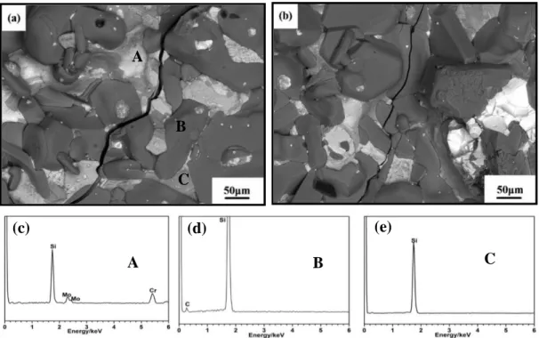
MoSi2, CrSi2 and Si. The backscattering micrograph of the coating is given in Figure 3-7.
Three phases can be clearly observed. Combined the XRD pattern (Figure 3-6) and the EDS analysis (Figure 3-7 (c-e)), the obtained three phases can be distinguished as the mixture of
MoSi2 and CrSi2 (noted as A), SiC (noted as B) and Si (noted as C) respectively. In addition,
as seen in Figure 3-7 (a) and (b), micro-crack is found on the surface. When cooled from the preparation temperature to room temperature, the CTE mismatch between the coating and the
32
C/C substrate resulted in the formation of the micro-crack. Compared with that of SMC-1, the size of micro-crack of SMC-2 is obviously decreased, implying that blasting treatment has a positive effect on relieving the CTE mismatch between the coating and the C/C substrate. Cross-section micrographs of the coatings are shown in Figure 3-8. The coating/substrate interfaces are distinguished by a red line. For SMC-1, a straight interface is observed, and only a little coating material is infiltrated into the C/C substrate. In contrast, an interlock coating/substrate interface is found for SMC-2.
Figure 3-7. Backscattered electrons micrograph and the spot EDS analysis of the Si-Mo-Cr coating, (a) SMC-1, (b) SMC-2, (c) EDS of Spot A, (d) EDS of Spot B, (e) EDS of Spot C.
Figure 3-8. Cross-section micrographs of the Si-Mo-Cr coatings, (a) SMC-1, (b) SMC-2. Figure 3-9 presents the adhesive strengths of the Si-Mo-Cr coating. With respect to SMC-1, the coating/substrate adhesive strength of SMC-2 is increased to about 26 MPa.
Coating C/C C/C Coating (e) C (c) A (d) B A B C
33
Figure 3-10 shows the XRD patterns of the Si-Mo-Cr coating after thermal cycling test. For
SMC-2 (Figure 3-10 (b)), the phases are SiC, MoSi2, SiO2 and Cr2O3. As for SMC-1 (Figure
3-10 (a)), the diffraction peak of C is detected, indicating the debonding of the coating and the exposure of C/C substrate. Surface micrograph of the coated C/C after thermal cycling test is given in Figure 3-11. After thermal cycling test, a glassy layer is formed on the surface. Combined with the XRD pattern (Figure 3-10), it can be deduced that the received glassy
layer is SiO2 + Cr2O3, which is good for hindering the oxidized species from attacking the C/C
substrate due to its low oxygen diffusion coefficient [68]. Some micro-cracks can be observed on the surface of SMC-2 (Figure 3-11 (b)). The micro-cracks are formed due to the thermal stress caused by the mismatch of CTE between the coating and the C/C during thermal
cycling test. With respect to SMC-2, the SiO2 + Cr2O3 glassy layer of SMC-1 is partially
peeled off with the exposure of C/C substrates, where bare carbon fibers could be clearly observed (Figure 3-11 (a)).
5 10 15 20 25 30 SMC-2 A d h e s iv e s tr e n g th ( MP a ) SMC-1
Figure 3-9. Adhesive strengths of the Si-Mo-Cr coated C/C composites.
34
Figure 3-11. Surface morphology after cyclic ablation test, (a) SMC-1, (b) SMC-2. CTE of bare C/C and the coated C/C composites are shown in Figure 3-12. Compared with the bare C/C composites, CTE of the coated C/C increases after applying the Si-Mo-Cr coating. In addition, it can also be seen that the CTE of SMC-2 is closer to that of bare C/C, indicating that the modified coating/substrate interface is beneficial for restricting the expansion of the coating materials as the temperature increases, thereby contributing to the CTE alleviation. This could explain why the size of surface micro-crack of SMC-2 is smaller than that of SMC-1 after the preparation of the Si-Mo-Cr coating (Figure 3-7). Combining the thermal cycling test results (Figure 3-11), the performance improvement of SMC-2 can be ascribed to the adhesive strength improvement and the CTE mismatch relief, thus improving its resistance to the erosion of the combustion gas.
Figure 3-12. Coefficients of thermal expansion of the C/C and the Si-Mo-Cr coated C/C.
Glassy layer
35
3.4 Blasting treatment combined with SiC nanowires to enhance the cyclic ablation performance of Si-Mo-Cr coating
In section 3.3, we find that although the construction of inlaid coating/substrate interface could improve the adhesive strength and thermal cycling performance of Si-Mo-Cr coating. But micro-cracks are still clearly observed on the coating after thermal cycling test. The introduction of a second phase into the Si-Mo-Cr coating is the mostly widely adopted strategy to tackle this problem so as to improve the toughness of the coating considerably. SiC nanowires are suitable to be used as the reinforcing materials due to their small size, high strength and toughness [70, 71]. In particular, SiC nanowires can impede the propagation of the micro-cracks, and then avoid the formation of penetration cracks [71]. In this section, coating/substrate interface modification and SiC nanowires introduction are combined to improve the performance of Si-Mo-Cr coating. In addition, to obtain a further understanding of the service reliability of the Si-Mo-Cr coating, the thermal cycling performance is studied using parallel oxyacetylene torch. For better comparison, in this section, the coated C/C composites with blasting treatment only are noted as SMC. The coated C/C composites with blasting treatment and in-situ grown SiC nanowires are noted as SMCnw.
3.4.1 Microstructure and cyclic ablation test
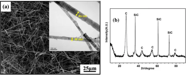
Figure 3-13 shows the surface morphology and XRD pattern of the as-prepared SiC nanowires. It is seen that SiC nanowires grow randomly and form a porous structure on the blasting treated C/C composites. From Figure 3-13 (b), C diffraction peak, corresponding to the C/C substrate, can be observed. The appearance of C peak further indicates that the prepared SiC nanowires layer is porous. During the preparation of the Si-Mo-Cr coating, the porous structure is beneficial for the diffusion of the coating materials into the C/C composites. The introduction of SiC nanowires is expected to improve the toughness of the coating, especially to decrease the occurrence tendency of micro-cracks. Figure 3-14 shows the surface morphology of the coating. Three phases (as seen in Figure 3-14 (b)) presenting
white (A), dark grey (B) and grey (C) color can be distinguished as the mixture of MoSi2 and
CrSi2, SiC and Si respectively (has been described in section 3.3). In addition, micro-crack is
observed on the surface of the coating. However, it can be observed that the size of micro-crack of SMCnw is reduced significantly.
Figure 3-15 shows the cross-section micrograph of the coating. With respect to SMC, an inlaid coating/substrate interface is also obtained in SMCnw, further confirming that the coating materials could diffuse through the porous SiC porous layer (Figure 3-13).
36
Figure 3-13. Surface morphology (a) and XRD pattern (b) of the SiC nanowires by CVD on the surface of the C/C composites with blasting treatment.
Figure 3-14. Typical morphology of the prepared coating, (a) SMC, (b) SMCnw.
Figure 3-15. Cross-section micrograph of the Si-Mo-Cr coating, (a) SMC, (b) SMCnw.
Cycling ablation test of the coated C/C composites from 1600 °C to room temperature is performed using parallel oxyacetylene torch (as described in Chapter 2). The mass loss per unit area is shown in Figure 3-16. The time of each cycle is set as 5 s. After 30 thermal
C/C Micro-crack Micro-crack B C A (b)
37
cycles, the mass loss per unit area of SMC is about 28 mg·cm-2. In contrast, the mass loss
per unit area of SMCnw is about 15 mg·cm-2. Therefore, it can be deduced that the
combination of blasting treatment and in-situ grown SiC nanowires can improve the thermal cycling performance of Si-Mo-Cr coating more effectively. According to the trend of the
curve, the mass loss curve can be divided into three stages, marked as S1, S2 and S3
respectively. The cyclic ablation behavior of the coating will be discussed according to the noted three stages later.
Thermal cycles 0 5 10 15 20 25 30 -5 0 5 10 15 20 25 30 35 40 Ma ss lo ss pe r un it ar ea /mg cm -2 SMC SMCnw
Figure 3-16. Mass loss per unit area of the Si-Mo-Cr coated C/C composites during thermal cycling test using oxyacetylene torch.
Figure 3-17 shows the surface morphology and EDS analysis of the sample after cyclic
ablation test. It can be observed that a glassy layer, deduced as SiO2 + Cr2O3 (Figure 3-17 (c)),
is formed. In addition, micro-crack is observed on the surface of both SMC and SMCnw after cyclic ablation test. The micro-crack can provide the entrance channel for the oxyacetylene
torch, and the protective ability of the formed SiO2+Cr2O3 glassy protective layer will be
degraded due to the shear action of oxyacetylene torch. With respect to the surface morphology of SMC (Figure 3-17 (a)), the size of micro-crack on the surface of S-2 reduces considerably after cyclic ablation test (Figure 3-17 (b)). Cross-section images of the sample after 30 thermal cycles are shown in Figure 3-18. It is found that penetrating crack is formed in the coating of SMC (Figure 3-18 (a)). In addition to the thickness decrease, the coating of SMCnw remains intact and no penetration crack is found (Figure 3-18 (b)).
38
Figure 3-17. Surface morphology of the Si-Mo-Cr coated C/C composites after thermal cycling test, (a) SMC, (b) SMCnw, (c) EDS analysis of Spot1.
Figure 3-18. Cross-section micrograph after cyclic ablation test, (a) SMC, (b) SMCnw.
3.4.2 Ablation mechanism
The gas environment of oxyacetylene torch is oxygen-rich. During the thermal cycling test, the following reactions will occur [72, 73]:
(3-1) (3-2) Crack Micro-crack (c) Spot1 Spot1 Micro-crack
39
(3-3)
(3-4)
(3-5)
(3-6)
Based on the above reactions, the oxidation of SiC, Si and CrSi2 (reaction (3-1)-reaction
(3-5)) is a mass gain process, while the oxidation of MoSi2 (reaction (3-6)) is a mass loss
process. From Figure 3-16, at the initial stage of the cyclic ablation test (S1), the ablation of
the coating gains mass. It is demonstrated that the oxidation of MoSi2 (reaction (3-6)) in a
short time has little impact on the mass change trend of the coating [73]. As a result, in this
stage, the mass gain can be mainly attributed to the formation of SiO2 and Cr2O3 (reaction
(3-1)-reaction (3-5)). Then with the increase of thermal cycles, at the stage of S2, the mass loss
per unit area is relatively stable, indicating that the formed glassy layer of SiO2 and Cr2O3
plays an effective role in resisting the attack of the oxyacetylene torch. At the stage of S3, the
mass loss per unit area rises quickly. Concerning the morphology before thermal cycling test (Figure 3-15), the thickness of both coatings is reduced after the test (Figure 3-18). During the conventional thermal cycling test in a high-temperature furnace, the coating thickness usually remains unchanged after thermal cycling test, and the corresponding mass loss is primarily attributed to the oxidation of C/C substrate. In this work, no obvious oxidation of C/C
substrate can be found (as shown in Figure 3-18). Hence, at the stage of S3, the increase of
mass loss per unit area can be mainly attributed to the reduction of coating thickness caused by the mechanical erosion of oxyacetylene torch. In addition, it can be found that the mass loss per unit area of SMCnw changes slowly (Figure 3-16).
18 20 22 24 26 28 30 SMCnw A d h e s iv e s tr e n g th (MP a ) SMC
40
To illustrate the role of SiC nanowires, adhesive strength and CTE testing are conducted. Figure 3-19 shows the adhesive strengths of the coating, which illustrates that the combination of blasting treatment and in-situ grown SiC nanowires can better improve the adhesive strength of the coating. Figure 3-20 shows the fracture surface morphology of the SMCnw sample. Some pullout nanowires can be observed. The pullout of SiC nanowires can dissipate fracture energy, resulting in the improvement of adhesive strength.
SiCnw diameter
Figure 3-20. Coating fracture surface morphology of the SMCnw sample.
Figure 3-21 shows the CTE of bare C/C and the Si-Mo-Cr coated C/C. It can be found that the C/C substrates present the similar thermal expansion behavior with the coated C/C composites under the same conditions. As a result, the measured results can reflect the CTE difference of the prepared coating. We can see that SiC nanowires are beneficial for restricting the expansion of the coating materials as the temperature increases. During cyclic ablation test, the thermal stress (σ) can be described as follows [74]:
(3-7)
where ∆T is the difference between cooling temperature and zero stress temperature, ∆α is the CTE difference between the coating and the substrate, E and ν are the Young’s modulus and Poisson ratio of the coating, respectively. Zero stress temperature can be assumed as the preparation temperature of Si-Mo-Cr coating. From equation (3-7), it can be found that the CTE mismatch has an obvious effect on the thermal stress during cyclic ablation test. With respect to SMCnw, the weaker bonding strength and the mismatch of CTE have caused higher thermal stress of SMC during cyclic ablation test, resulting in the formation of micro-crack or even penetrating cracks (Figure 3-17 (a) and Figure 3-18 (a)). As a result, the protective
ability of the formed protective layer of SiO2 and Cr2O3 will be degraded. This could be the
![Figure 1-3. Requirements for the coating on the surface of C/C composites [2, 11].](https://thumb-eu.123doks.com/thumbv2/123doknet/14600192.731013/10.892.180.700.113.333/figure-requirements-coating-surface-c-c-composites.webp)
![Figure 1-4. Schematic diagram of the SiC coating prepared by pack cementation [21].](https://thumb-eu.123doks.com/thumbv2/123doknet/14600192.731013/11.892.290.656.102.357/figure-schematic-diagram-sic-coating-prepared-pack-cementation.webp)