HAL Id: hal-00456101
https://hal.archives-ouvertes.fr/hal-00456101
Submitted on 1 Sep 2016
HAL is a multi-disciplinary open access archive for the deposit and dissemination of sci-entific research documents, whether they are pub-lished or not. The documents may come from teaching and research institutions in France or abroad, or from public or private research centers.
L’archive ouverte pluridisciplinaire HAL, est destinée au dépôt et à la diffusion de documents scientifiques de niveau recherche, publiés ou non, émanant des établissements d’enseignement et de recherche français ou étrangers, des laboratoires publics ou privés.
Flattened Simulation Structure: Application to
High-Level Architecture (HLA) Compliant Simulation of
Workflow
Grégory Zacharewicz, M. E.-A. Hamri, C. Frydman, N. Giambiasi
To cite this version:
Grégory Zacharewicz, M. E.-A. Hamri, C. Frydman, N. Giambiasi. A Generalized Discrete Event System (G-DEVS) Flattened Simulation Structure: Application to High-Level Architecture (HLA) Compliant Simulation of Workflow. SIMULATION, SAGE Publications, 2010, 86 (3), pp.181-197. �10.1177/0037549709359357�. �hal-00456101�
Abstract— The objective of the paper is to specify a new
flat-tened G-DEVS simulation engine structure and the Workflow M&S environment embedding it. We express first the new flat-tened simulation structure and give the corresponding transfor-mation functions. We analyse performance tests conducted on this new simulation structure to measure its efficiency. Then, having selected the essential concepts in the elaboration of Work-flow, we present a language of description to define Workflow processes. Finally, we define a distributed Workflow Reference Model that interfaces components of the Workflow with respect to the HLA standard.
Today enterprises can take advantage of using this platform in the context of networking where interoperability, flexibility, and efficiency are challenging concepts
Index Terms—DEVS, G-DEVS, Flattened Simulation
Struc-ture, Distributed Simulation, HLA, Workflow, Enterprise In-teroperability.
I. INTRODUCTION
EVS [1] is a well-known formalism to describe the be-haviour of complex systems. Its formal framework sepa-rates modelling from a simulation process. DEVS is a power-ful M&S formalism, with a clear semantics and modular ap-proach. It is based on event and state concepts (the simulation is event-driven, which makes it faster). However, we based our works on the DEVS extension: Generalized-DEVS (G-DEVS) [2]. In this formalism, event and state trajectories are polynomials (multi values) instead of piecewise linear con-stants trajectories like DEVS, and thus represent complex continuous phenomena more precisely. On the simulation side, G-DEVS keeps the DEVS semantics specification. Neverthe-less the hierarchical simulation structure in DEVS/G-DEVS results from the user-specified modelling structure (e.g. multi hierarchical imbrications’ reuse of previous models); we pos-tulate that this feature is not required at simulation run time.
Author G.Z. is with the laboratory IMS-LAPS/GRAI, Université Bordeaux – CNRS, 351, cours de la Libération, 33405 Talence cedex. (Corresponding author: tel: +335-4000-6532; e-mail: [email protected].)
Authors M.H., C.F., and N.G. are with the Laboratory of Science and In-formation Systems UMR CNRS 6168, Université Paul Cézanne, Avenue Escadrille Normandie Niémen, 13397 Marseille cedex 20, FRANCE; e-mails: {amine.hamri, claudia.frydman, norbert.giambiasi}@lsis.org.
From that postulate, we propose a new simulation structure that is simplified (flattened) to increase execution speed.
An applicative goal of such M&S structure can be found in representing industrial processes (Workflow). Indeed, this field is recent (early 1990s [3]) and not fully standardized. The Workflow Management Coalition (WfMC) works at standard-izing this field; it provides a consistent high level framework to develop the business process. The Workflow specification involves different tasks, items, applications, and actors which are essential to its execution. This specification is quite intui-tive (it can be automatically generated from a graphical speci-fication) and the user does not need to develop programming code. The lack of Workflow M&S is, in addition to most ven-dor tools not conforming to WfMC standard, the missing for-mal simulation semantics associated with Workflow engines. Clearly, the Workflow M&S is a semi-formal language to model user requirements and then, most of the Workflow simulations engines are ad hoc. Consequently, the Workflow does not guarantee a formal and clear semantics. This fact may lead to incompatibility and errors that are difficult to detect (like coding errors, codes that do not conform to the Workflow specification, etc.). A solution can exist in more formal model-ling. However Workflow users are not familiarized with for-mal specifications (e.g. DEVS). Thus we have proposed in [4] to automatically transform high level graphical Workflow specifications to G-DEVS models feeding a new embedded efficient G-DEVS simulator. In addition, current complex industrial processes need to interoperate [5], being combined, and to cooperate with heterogeneous distributed components. HLA is a distributed simulation and execution standard origi-nally defined for interoperability of US military simulation tools and now employed in the civilian domain; it can address actual enterprise requirements. From the preceding enounced challenges and to address their requirements, we introduce in this paper a HLA-compliant Workflow Modelling Environ-ment.
The paper is organized as follows. Section 2 gives an over-view of G-DEVS, HLA, and Workflow. Section 3 details the specification of the new flattened G-DEVS simulation struc-ture proposed, gives the transformation functions, and reports on performance results of this new simulator. Section 4 pre-sents the integration of the G-DEVS flattened simulator in an HLA context. Section 5 introduces the application field of our environment and gives keys to transform a Workflow
graph-A Generalized Discrete Event System
(G-DEVS) Flattened Simulation Structure:
Application to High-Level Architecture (HLA)
Compliant Simulation of Workflow
G. Zacharewicz, M.A. Hamri, C. Frydman, N. Giambiasiical specification into a G-DEVS executable model. In addi-tion we describe the new HLA compliant Workflow Model-ling platform. Finally, we conclude by introducing our future works and conclusion.
II. RECALL
A. G-DEVS
G-DEVS emerged with the drawback that most classical discrete event abstraction models (e.g. DEVS) face: they ap-proximate observed input–output signals as piecewise constant trajectories. G-DEVS defines abstractions of signals with piecewise polynomial trajectories [2]. Thus, G-DEVS defines the coefficient-event as a list of values representing the poly-nomial coefficients that approximate the input–output trajecto-ry. Therefore, a DEVS model, from the founding point of view, is a zero order G-DEVS model (the input–output trajec-tories are piecewise constants).
G-DEVS keeps the concept of the coupled model intro-duced in DEVS [1]. Each basic model of a coupled model interacts with the others to produce a global behaviour. The basic models are either atomic or coupled models that are already stored in the library. The model coupling is done with a hierarchical approach (owing to the closure under coupling of G-DEVS, models can be defined in a hierarchical way).
On the simulation side, G-DEVS models employ abstract simulator, proposed in [1], which defines the simulation se-mantics of the formalism. The architecture of the simulator is derived from the hierarchical model structure. Processors involved in a hierarchical simulation are Simulators which insure the simulation of atomic models, Coordinators, which insure the routing of messages between coupled models, and the Root Coordinator, which ensures global simulation man-agement. The simulation runs by sending Imessage to all Co-ordinators and Simulators, and continues by exchanging spe-cific messages (*message for internal event, Xmessage for external event and Ymessage for output event) between the different processors. The specificity of G-DEVS model simu-lation is that the definition of an event is a list of coefficient values as opposed to a unique value in DEVS.
B. DEVS flattened simulation structure
To facilitate the introduction of the G-DEVS flattening, we recall DEVS flattening techniques.
Kim et al. [6] presented a methodology of distributed simu-lation for models specified in the DEVS formalism. The methodology transforms a hierarchical DEVS model into a non-hierarchical one. This transformation reduces the overload of information handled during a conventional and classical hierarchical simulation of DEVS models and facilitates the synchronization of distributed simulation, thus increasing the stability of the simulation engine. To demonstrate the efficien-cy of the proposed methodology, the authors developed a simulation environment in Visual C++ and conducted a per-formance evaluation on the simulator applied to a large-scale logistics system. The results of performance measurements show that the new proposed methodology works efficiently
and offers better performances than the previous approaches in terms of execution time.
Glinsky [7] developed DEVStone; this software was dedi-cated to the automation of the evaluation of surrounding areas of simulations based on DEVS. DEVStone analyses the per-formance of successive versions of the same simulation engine (e.g. further to an update or further to a problem being solved), and supplies common metrics to compare the environments of different M&S. The studies realized with DEVStone have notably allowed it to be concluded that generally the technique of “flattened” simulation (previously developed by the au-thors) surpasses the hierarchical shape, reducing the overhead of information handled by up to 50%, and thus supplies im-proved answer times and a higher percentage of successes in the execution. Therefore, the use of the non-hierarchical ap-proach allows the simulation of bigger models with better execution results. These results are a consequence of the re-duced number of messages exchanged in the flat mechanism of simulation.
C. High Level Architecture (HLA)
High Level Architecture (HLA) is a software architecture specification that defines how to create a global simulation composed of distributed simulations. In HLA, every partici-pating simulation is called federate. A federate interacts with other federates within an HLA federation, which is in fact a group of distributed federates. The HLA set of definitions brought about the creation of Standard 1.3 in 1996, which then evolved into HLA 1516 in 2000 [8].
The interface specification of HLA describes how to com-municate within the federation through the implementation of the HLA specification: the Run Time Infrastructure (RTI).
Federates interact using the services proposed by the RTI. They can notably “Publish” to inform about an intention to send information to the federation and “Subscribe” to reflect some information created and updated by other federates. The information exchanged in HLA is represented in the form of classical object-oriented programming classes. The two kinds of objects exchanged in HLA are Object Classes and Interac-tion Classes. The first kind is persistent during the simulaInterac-tion, the other is only transmitted between two federates. The data interchange objects format is XML specified but does not constrain the implementation. More details on RTI services and distributed data in HLA can be found in the HLA stand-ardization book [8].
In addition, in order to respect the temporal causality rela-tions in the simulation, HLA proposes to use classical con-servative or optimistic synchronization mechanisms [9].
D. Workflow
Workflow is the modelling and the computer assisted man-agement of all the tasks to be carried out and the various ac-tors invoked in the realization of a business process [3]. The purpose of WfMC is to develop standards in the field of Workflow in association with the main actors of the domain [10], [11]. It defines a Workflow Reference Model presenting the components of a Workflow. It contains the process
defini-tion tool, the administrator tool, the Workflow client applica-tion, the invoked applications, and the link between other Workflow environments. We focus on the process definition phase to make it computerized.
A Workflow consists of procedures (also called tasks) and logical expressions (controllers) that describe the paths for items. A Workflow can be described by a graphical represen-tation (specification) in which tasks are represented by rectan-gles and controllers are represented by nodes and arrows that drive the flows over tasks [10].
Many environments dedicated to the specification and the simulation of Workflows exist. Most of them are based only on ad hoc execution engines, so they do not profit from the concepts offered by the simulation theory [1]. In fact, this theory separates the modelling phase from simulation, allow-ing the reuse of validated specifications in different domains.
The small part of environments settled on formal specifica-tion is Petri nets based (e.g. Yasper [12], Yawl [13], and so on). For instance, Yasper is composed of an editor client to represent the process definition graphically and a Petri nets powered runtime engine. They argued the choice of using Petri nets by the formal semantics nature, (despite the graph-ical representation), the state-based concept instead of event-based, and the numerous existing analysis techniques.
We believe that a simulation tool based on the DEVS/G-DEVS formalism can facilitate the modelling thanks to modu-larity and pragmatism; it then supplies simulation results with a better probability because of the explicit time management, and finally the model description and validation process is open source, so models can be exported, compared, and re-used. Nevertheless, we agree that, from a computational point of view, no computational power is added by DEVS compared to other modelling formalisms [14]. In detail, Zeigler [1] dis-cussed the advantages that can be provided by DEVS (or by extension, obviously, by G-DEVS) modelling. DEVS model-ling can be more convenient for our purpose (i.e. workflow modelling) than Petri nets modelling: firstly it gives a more general framework for M&S of systems by handling explicitly the notion of time, in particular the autonomous timed evolu-tion of the model (while an extension of the original definievolu-tion is required for Petri nets), secondly it proposes modular hier-archical modelling facilities by reusing previously developed models, and events exchanged between models can contain several pieces of information, and finally it offers a formal definition of the simulator (simulator implementation and results can be mastered more easily and better compared).
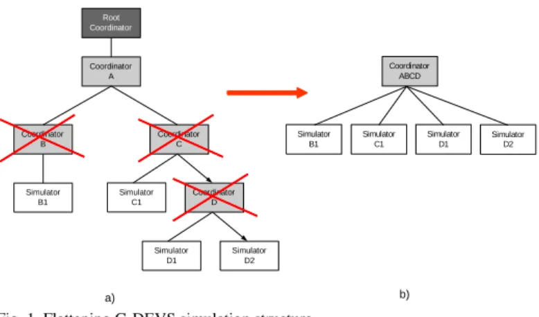
III. NEW DEVS/G-DEVSSIMULATION STRUCTURE The previous works all agree in terms of the performance of the “flattened” DEVS structure with regard to the hierarchical structure (i.e. § B). As a consequence, in our G-DEVS simula-tor we chose to use a simulation structure inspired by the hier-archical structure of abstract simulation defined in Zeigler [1], but containing only two hierarchical levels. This structure is called “compact”, (e.g. Fig. 1.b).
From the works introduced in Kim [6] and Glinsky [7] and
with the aim of decreasing the exchange of messages between the intermediate coordinators and the simulators, we suggest reducing the treelike structure of intermediate coordinators between the root coordinator and simulators. To achieve this goal, we chose to keep only one coordinator component to which atomic simulator components will be connected in direct succession. The reduction of the simulation structure is illustrated by the suppression of components that are crossed out in Fig. 1 a). This new structure, after reduction, is present-ed in Fig. 1 b).
Two main solutions can be distinguished to flatten models for simulation.
The first solution consists in preserving the coupled models with all their hierarchy as a storage format. Only at simulation setting time does the environment explore the treelike struc-ture of the considered model to get back the atomic models on the leaves. This solution presents the advantage to be compe-tently applied to a classical implementation of DEVS (or G-DEVS) coupled model. The drawback is it requires an algo-rithm of deep treelike data structure exploration, which can be slow in the case of a complex coupled model. Previous works by Kim [6] and Glinsky [7] have exploited this solution.
The second solution consists in making a flattening trans-formation on saving each model step or when launching it for simulation. In that case, the considered models contain at most two hierarchical levels because the included models resulting from the library have been preliminarily flattened during sav-ing. This solution implements less complex exploration algo-rithms; in return all included models must have been flattened previously.
We select the second solution because the exploration algo-rithm is less complex and so its execution on models and cou-pling structures is faster. At the end, our solution consists in archiving both a hierarchical model (for editing and compos-ing models) and a non-hierarchical model (for simulation).
Fig. 1. Flattening G-DEVS simulation structure
A. LSIS_DME model class diagram
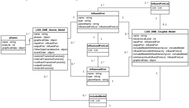
The class diagram specified for the G-DEVS M&S envi-ronment developed by LSIS (called LSIS_DME [15]), pre-sented in Fig. 3, is based on the original DEVS model classes structure proposed by Zeigler [1]. However, the tool integrates a specific data structure for graphical model editing and for
Root Coordinator Coordinator B Coordinator D Coordinator C Coordinator A Simulator B1 Simulator D1 Simulator C1 Simulator D2 Coordinator ABCD Simulator B1 Simulator C1 Simulator D2 Simulator D1 a) b)
model flattening. These functions, sets, and relations will be used in Fig. 3 and 4 detailed in the next point.
1) LSIS_DME atomic model classes structure
The class model description of the LSIS_DME G-DEVS atomic model (cf. Fig. 3) possesses the classical functions defined in the DEVS formalism [1]. It possesses a specific attribute: phase (a state variable for graphic representation). Also, the attribute OtherStateVariablesSet is employed to define other state variables that describe the model global state. It also possesses an attribute eventOrder defining the degree of the polynomial event and states in G-DEVS models. Finally, it contains an attribute graphicalData to store the information relative to the graphical representation of the model (size of box, position, etc.). This last attribute only has a meaning for reusing graphical models and optionally to run a step by step animated state simulation.
2) LSIS_DME coupled model classes structure
Fig. 3 also presents the LSIS_DME_Coupled_Model class to implement a G-DEVS coupled model. This class contains a list of influent ports: influentPortListWithHierarchy, de-fining the influent input ports of the models, each of these ports making reference to a list of influenced ports: Influ-encedPortList. With regard to the original representation of Zeigler [1], this class contains in addition the specific attrib-utes includedModelWithoutHierarchyList and nonHierar-chicalInfluentPortList describing the non-hierarchical coupled model generated by the flattening algorithm from the coupled model created by the tool user. These data are stored in a list of objects.
B. Model transformation function
We focus now on attributes of the coupled model data struc-ture of LSIS_DME (cf. Fig. 3) related to the flattening
func-tion. The attribute includedModelWithHierarchyList con-tains (itself) a set of includedModel (atomic or coupled mod-els). The attribute includedModelWithoutHierarchyList contains a list of non-hierarchical includedModel (atomic). When creating a model, this last list is initially empty.
The pseudo code in Fig. 2 specifies the flatteningModels function of LSIS_DME. This function generates the set of atomic models to store in includedModelWithoutHierar-chyList from the hierarchical models of includedModel-WithHierarchyList. This function is called when saving a model in the library or during an initialization preceding the execution of a simulation. The flatteningModels function goes through the includedModelWithHierarchyList set; for every includedModel, a test is performed. If this sub-model is atomic, it is copied in includedModelWithoutHierarchyList. If this sub-model is coupled, all the models contained in this sub-model are found recursively (using a tree-like structure exploration) and copied in the includedModelWithoutHier-archyList of the considered model.
includedModelWithoutHierarchy flatteningModels (consideredCou-pledModel)
for (all includedModel in consideredCoupledMod-el.includedModelWithHierarchyList)
if (includedModel.hierarchicalLevel == 0) // no hierarchy includedModelWithoutHierarchyList add (includedModel) else // the included model is hierarchical
for (all includedModelWithoutHierarchy’ in includedMod-el.includedModelWithoutHierarchyList)
includedModelWithoutHierarchyList add (includ-edModelWithoutHierarchy’)
Fig. 2. LSIS_DME model’s flattening function
To summarize, models contained in the non-hierarchical models list are not modified; they (or their sub-models) are just copied in the non-hierarchical models list. Indeed the includedModelWithHierarchyList is still used for modelling purposes, and remains modular and hierarchical.
Fig. 3. LSIS_DME G-DEVS coupled model class diagram
+externelTransitionFunction() +internalTransitionFunction() +confluentTransitionFunction() +outputFunction() +timeLifeFunction() -name : string -phases : object -graphicalData : object -inputPort : InfluentPort -outputPort : InfluentPort -OtherStateVariablesSet : object -eventOrder : object LSIS_DME_Atomic_Model -name : string -timeLife : int -graphicalData : object phases 1..* 1 -name : string -hierarchicalLevel : int -inputPort : InfluencedPort -outputPort : InfluentPort -includedModelWithHierarchyList : includedModel -influentPortListWithHierarchy : InfluentPortList -includedModelWithoutHierarchyList : includedModel -nonHierarchicalInfluentPortList : InfluentPortList -graphicalData : object LSIS_DME_Coupled_Model -name : string -type : string -parentName : string -InfluencedPortList : InfluencedPortList InfluentPort 0..* 1 -name : string -type : string -parentName : string InfluencedPort 0..* 1 0..* 1 0..* 1 -List : List InfluencedPortList 1 1 1..* 1..* -List : List InfluentPortList 0..1 1 1..* 1..* -List : List includedModel 1 1 0..* 0..*
C. Model coupling transformation function
Flattening a model also requires the transformation of in-cluded models coupling. Indeed, the coupling relations of a flattened model have to refer only to atomic models of the non-hierarchical model and to the unique coupled model level. The pseudo code in Fig. 4 considers the CouplingTrans-formation function of the environment. This function gener-ates a set of coupling relations between atomic models and the considered model from the hierarchical coupling relations.
The coupling relations are defined as a set of influent ports, where each element is linked to one or more influenced ports. The coupling flattening algorithm is divided into two parts: the influent ports of the coupling relation are handled in the first part, and the influenced ports are handled in the second part.
The first part of the algorithm identifies the influent ports of the non-hierarchical model that will be inserted into nonHier-archicalInfluentPortList of the model. Every influ-entPort of InfluentPortListWithHirearchyList is thus analysed. If it has the considered model or an atomic model as parent, this coupling relation is directly copied in an interme-diate list IntermediaryInfluentPortList, which contains all the coupling relations with influent ports referring only to
atomic or considered models. If the influentPort has an included model as parent, the contents of this included model must be analysed to determine the influent sub-models of the considered influentPort and create a newInfluentPort for every included port influencing it. The part concerning ports influenced by the influentPort is copied out in every newIn-fluentPort. Every newInfluentPort is added to Intermedi-aryInfluentPortList.
The second part of the algorithm handles the list Interme-diaryInfluentPortList. Every influenced port ( influ-encedPort’) from the list influencedPortList of every in-fluentPort’ must be analysed. If the influencedPort’ struc-ture has as parent the considered model or an atomic model, a simple copy is made in the influenced ports list by newInflu-entPort’. In the other case, influencedPortList of newIn-fluentPort’ is completed by every influenced port by in-fluencedPort’ recursively found inside the sub-models of the parent of influencedPort’. Then, these structures are added to the definitive nonHierarchicalInfluentPortList.
Finally, the internal coupling relations between included atomic models are copied in the final nonHierarchicalInflu-entPortList list.
nonHierarchicalInfluentPortList CouplingTransformation (consideredCoupledModel)
for (all influentPort in consideredCoupledModel.InfluentPortListWithHierarchy) // upstream part of influence relation
model = Retrieve parent with (influentPort.parentName)
if (model != consideredCoupledModel && model != AtomicModel) // parent of port is not the coupled model
includedModel = model // it is an included model
for (all influentPortInIncludedModel in includedModel.influentPortList)
for (all influencedPortInIncludedModel in influentPortInIncludedModel.influencedPortList) if (influencedPortInIncludedModel == influentPort)
Create newInfluentPort
newInfluentPort.name = influentPortInIncludedModel.name
newInfluentPort.parentName = influentPortInIncludedModel.parentName newInfluentPort. influencedPortList = InfluentPort. influencedPortList add newInfluentPort in IntermediaryInfluentPortList
else add influentPort in IntermediaryInfluentPortList // list for computation purpose only for (all influentPort’ in IntermediaryInfluentPortList) // downstream part of influence relation
for (all influencedPort’ in influentPort’. influencedPortList)
influencedModel = Retrieve parent with (influencedPort’.parentName)
if (influencedModel is non hierarchical || influencedModel is consideredCoupledModel) // no change in coupling (no
hierarchy)
newInfluentPort’ = influentPort’ // simple copy
else // influencedModel is hierarchical
newInfluentPort’.name = influentPort’.name
newInfluentPort’.parentName = influentPort’.parentName
for (all influentPorIntIncludedModel in influencedModel. influentPortListWithoutHierarchy) if (influentPorIntIncludedModel.name == influencedPort’.name)
for (all influencedPort in influentPorIntIncludedModel.influencedPortList)
newInfluentPort’.influencedPortList add influencedPort add newInfluentPort’ in nonHierarchicalInfluentPortList
for (all includedModel in consideredCoupledModel.includedModelWithHierarchyList) for (all InfluentPort’’ in includedModel.InfluentPortListWithHierarchy)
for (all InfluencedPort’’ in InfluentPort.influencedPortList)
if (InfluentPort’’ parent is AtomicModel && InfluencedPort’’ parent is AtomicModel) if (InfluentPort’’ is already in nonHierarchicalInfluentPortList)
add InfluencedPort’’ in InfluentPort’’.influencedPortList
else add InfluentPort’’ in nonHierarchicalInfluentPortList
D. Performances of “flattened” LSIS DME simulators
In [4] and [15], we introduced an environment that we called LSIS_DME (listed on G. Wainer’s website “DEVS Tools” [16]) for creating G-DEVS graphical models and simu-lating them. We developed two simulation engines to power it: a non-hierarchical simulator and a hierarchical simulator. We realized performance comparison tests between those two engines to elect the most efficient one for powering the final version of our M&S environment. In this part, we propose the comparison result of our study.
The configuration of our test simulation platform was a Pentium III 2.4 GHz with 512 Mb de RAM under Windows XP. Both simulators (hierarchical and non-hierarchical) were implemented in Java. The measurements were realized with JRat tool [17], allowing us to measure performances in Java programs by including specific classes that perform quantita-tive measurements on the execution of code. We precise that all the considerations enounced in this section and the next one are valid for using LSIS_DME software.
1) Russian Dolls Imbrications
We executed the comparison study on G-DEVS coupled models whose characteristics expressed a representative range of graphically conceivable models. They were realistic and able to have been proposed by a modeller (not automatically generated with no connection to realistic models). We focused in this paper on the study of two G-DEVS coupled models of logical gate circuits.
Various tests were realized for the same models with different levels of hierarchy using “Russian Dolls” Imbrications (RDI) for each atomic model. These imbrications consist in recur-sively inserting an atomic model into a coupled model with the same input and output ports on the outer model automati-cally linked with inner model ports.
The first coupled model A characterizes a simple model composed of logical gates (2 AND Gates, 1 OR gate and 1 NAND gate) weakly coupled with the input/output and be-tween them, the logical model is depicted in Fig. 5. In DEVS representation, we illustrate for e.g. a four hierarchical RDI (for each atomic model) of model A in Fig. 6.
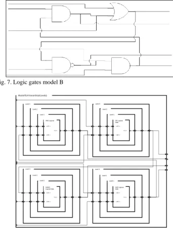
The coupled model B contains the same atomic models (2 AND Gates, 1 OR gate and 1 NAND gate) but it possesses a more important number of couplings between the coupled sub-models, the logical model is depicted Fig. 7. For e.g., we illus-trate, in DEVS coupled representation, a four hierarchical RDI of model B in Fig. 8. We confound the degree of encapsula-tion with the number of dolls).
In detail, for each of these types of models we defined a more or less hierarchical RDI of the model and coupling. Note that the A and B flattened models (zero level RDI) contain the same four G-DEVS atomic models of logical components inter-coupled differently on a unique hierarchical level. The tests were run with one to twelve hierarchical RDI levels for each model. For each of these structures we executed a signif-icant number of replications to compare them as objectively as possible. The simulations were set with 100 to 1000 input
events planned.
Fig. 5. Logic gates model A
Fig. 6. Four hierarchical levels RDI G-DEVS coupled model A
Fig. 7. Logic gates model B
Fig. 8. Four hierarchical levels RDI G-DEVS coupled model B AND Logical Gate « e2 » « s » « e1 » OR Logical Gate « e2 » « s » « e1 » NAND Logical Gate « e2 » « s » « e1 » AND Logical Gate « e2 » « s » « e1 » Level 1 Level 2 Level 3
Model A (4 hierarchical levels)
Level 1 Level 2 Level 3 Level 1 Level 2 Level 3 Level 1 Level 2 Level 3 AND Logical Gate « e2 » « s » « e1 » OR Logical Gate « e2 » « s » « e1 » NAND Logical Gate « e2 » « s » « e1 » AND Logical « e2 » « s » « e1 » Level 1 Level 2 Level 3
Model B (4 hierarchical Levels)
Level 1 Level 2 Level 3 Level 1 Level 2 Level 3 Level 1 Level 2 Level 3
2) Fractal Imbrications
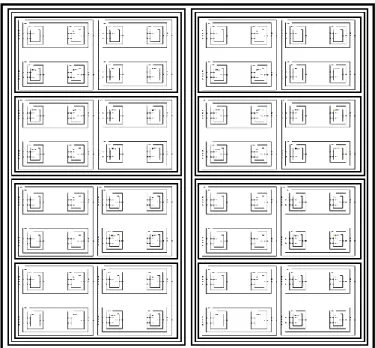
In addition, to validate our approach, we have proposed a second way of coupling models, maybe more practical accord-ing to modeller’s customs. In this approach, we have coupled recurrently models A or B in Fractals (like) Imbrications (FI) to built Coupled Models CMA and CMB. Therefore, the mod-els (A or B) have been coupled by 2, then 4, and so on recur-sively to 256 (the Fig. 9 depicts 64 models). Each coupling is adding a hierarchical level, so in the example depicted Fig. 9, the hierarchical level is 7 (2 levels for initial coupling by 2 and one more each 4, 8, 16, 32 and 64 models). Further to the picture, we have automatically built up to nine hierarchical FI levels for the tests with 256 Atomic models. We notice that coupling relations are not depicted in the Fig. 9 to remain generic to the representation of CM* (A or B) models and not to complicate the figure.
Fig. 9. Seven hierarchical levels FI DEVS CM* Model
3) Simulation Results
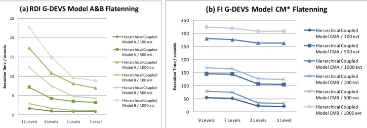
Fig. 10a. and b. reports tests performed on LSIS_DME hosting JRat [17]. The execution time has been registered, according to the number of hierarchical RDI levels (from 1 level to 12 levels) for A, B models (4 atomic models) and from1 level to 9 FI levels for CMA and CMB (256 atomic models). The simulation has been launch for 100, 500, 1000 events planned. Several replications of same configuration have been performed for each case to determine an arithmetic mean.
It shows a growth of the execution overhead between a non-hierarchical structure (zero RDI or FI level) and when increas-ing (up to twelve levels) the RDI or FI hierarchical structure of the considered model. In Fig. 10a, the flattening reduces con-siderably the execution time in the flattened structure, in
par-ticular for numerous events planned. For e.g., for the model B with 1000 events planned, the simulation reduce 13 seconds of execution when reducing from twelve levels to one level. These results are consistent with previous studies recalled in § III.B.
E. Limitation of “flattened” LSIS DME simulators
Nevertheless, the graph representation of simulation run shows, in Fig. 10b, that for complex models (CMA and CMB with FI hierarchical levels) the tendency to decrease overhead when reducing the models imbrications is slowed down. The gain of the flattening is inflected with important number of event to treat (between 500 and 1000 and up). In that case, we should discuss about the necessity to flatten the structure, because we must compare the simulation duration cutback with the flattening duration, done offline before simulation. We believe that the lack of gain is due to large lists of events and lists of models handled. The time required for handling, searching and classifying information appears to limit (but not to reverse) the performance in the case of large number of models and events to treat. Literature can give solution to this kind of problem. Indeed, the commonly admitted lack in the flattened simulation structure is due to the management of lists of events and models that contain many elements.
In more detail, the problem of large event-schedulers and model lists comes from the insertion, finding, removing and sorting of a new element. It can be improved thanks to cus-tomizable heuristics depending on lifetime of model states. An example of such heuristic can be given by the heuristic that consisted in defining one scheduler for the close future (with adjustable deadline) and a second event scheduler for the far-away future proposed by Giambiasi [18] and Miara [19]. In that case, the number of schedulers and their management is depending on simulated models parameters and on delays described in the models but not on the model structure de-scribed by the modeler. In addition, it is clear that the number of messages exchanged in this kind of approach is not in-creased and the number of events is limited in each scheduler. We should keep in mind that most relevant results for us remain in use of human made models with relatively low complexity of behavior and structure. As well, we consider human controlled number of handled events in opposition to auto-generated models and events. The capacity to use and reuse of G-DEVS models from shared user libraries to make them interoperable is also a core consideration.
Finally, our goal is to balance simulation performance re-quirements with the necessity of interoperability of M&S platform with other software components. We present in the next section, the use of the HLA standard to facilitate the interoperability of the simulation platform with distributed components.
Fig. 10. Comparing performances of flattened and hierarchical structures
I. G-DEVS/HLACOMPONENTS MAPPING
We proposed in [4] to extend LSIS_DME in order to split a G-DEVS model structure into distributed federate component models (e.g. Fig. 10). The global G-DEVS model structure is recomposed into an HLA federation (i.e. a distributed coupled model). The environment maps a G-DEVS Local Coordinator and Simulators into HLA federates and maps the Root Coor-dinator into RTI. Thus, the “global distributed” model (i.e. the federation) is constituted of intercommunicating federates.The G-DEVS model federates intercommunicate by publishing and subscribing to HLA interactions that map the coupling rela-tions of the global distributed coupled model. This information is routed between federates by the RTI with respect to time management and the Federation Object Model description [8]. In fact, in [20] and [21], we developed an algorithm for G-DEVS federation execution with a conservative synchroniza-tion mechanism using a positive Lookahead value gained from the HLA LITS value.
Fig. 11. G-DEVS distributed simulation structure
II. TRANSFORMING A WORKFLOW SPECIFICATION INTO A G-DEVSMODEL
Workflows are most commonly graphically modelled. The drawback of this representation is the fact that it is not based on strong formal concepts. Thus, it does not allow properties of semantic verification and validation of the model. Further-more, these models are often simulated by ad-hoc engines that could not be compared in terms of correctness and efficiency in relation to others. From this postulate, in [22], we proposed to define a unified language for the specification of Workflow to be applied as a common output of Workflow editors. This language supports algorithms to transform a Workflow model into a classical formal specification for simulation inde-pendently of the Workflow editor.
A. Workflow representation
The WfMC proposed an XML representation of Workflow established as a standard in the Workflow community [11]. Instances of XML Workflow process model structures’ cor-rectness can be certified by referring to the WfMC Workflow Document Type Definition (DTD). This XML representation is not fully convenient for the XML specification of produc-tion Workflow. Thus, we proposed in [22] a simple language to represent the components involved in that kind of Work-flow.
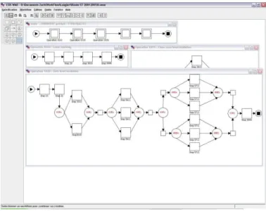
An XML Workflow process model is composed of task components, which handle items with resources, and control-ler components that route items between tasks. Items pass over a sequence of these components. These components are linked by directed arcs in order to define a graphical component based model specification. Examples of complex processes descriptions addressed by the definition of the Workflow blocks library have been presented in [22]. Fig. 11 presents a print screen of the environment with Workflow sample mod-els. 0 5 10 15 20 25
12 Levels 6 Levels 2 Levels 1 Level
Exe cut ion T im e / s e con ds
(a) RDI G-DEVS Model A&B Flatenning
Hierarchical Coupled Model A / 100 evt Hierarchical Coupled Model A / 500 evt Hierarchical Coupled Model A / 1000 evt Hierarchical Coupled Model B / 100 evt Hierarchical Coupled Model B / 500 evt Hierarchical Coupled Model B / 1000 evt 0 50 100 150 200 250 300 350
9 Levels 7 Levels 2 Levels 1 Level
Ex ecu ti on T im e / se co nd s
(b) FI G-DEVS Model CM* Flatenning
Hierarchical Coupled Model CMA / 100 evt Hierarchical Coupled Model CMA / 500 evt Hierarchical Coupled Model CMA / 1000 evt Hierarchical Coupled Model CMB / 100 evt Hierarchical Coupled Model CMB / 500 evt Hierarchical Coupled Model CMB / 1000 evt
Interconnection Netw ork Central RTI Component Simulator B1 Simulator C1 Simulator D2 Simulator D1 Computer 1 Computer 2 Computer 3 Local Coordinator AB Local Coordinator ACD Local RTI Component Local RTI Component GDEVS Federate 1 GDEVS Federate 2
Fig. 12. LSIS Workflow Model Editor (WME)
The Workflow blocks description presented in Zacharewicz [22] challenges the descriptions by Russell in [13] and Van Der Aalst in [23] and [24]. This description defines classical task blocks and routing sequence blocks; for example Fig 12 (the most relevant blocks have been detailed in [22]). In addi-tion to the coexisting Workflow cited, this descripaddi-tion pro-posed blocks to explicitly manage the stock levels of goods at run time and blocks containing algorithms for resources allo-cation in tasks.
These concepts have been implemented into the Workflow modelling tool LSIS_WME (developed at LSIS). This tool allows us to graphically describe a Workflow (the interface shown in Fig. 11 presents the interface of this software) and to store the model in an XML format. This software has been presented in detail in [22], and we invite the reader to refer to this document for more details.
Finally, emerging works on human or machine behaviour modelling by DEVS model blocks, as defined by Seck [25], have been tested in the environment. Therefore, the simulation can provide statistical studies on the Workflow reaction re-garding human behaviour tuning; this last step is still under our scope of study.
B. G-DEVS representation
In [22], we proposed a method to transform the (semi-formal) Workflow graphical models into ((semi-formal) G-DEVS coupled models by connecting G-DEVS atomic models repre-senting the Workflow basic components. The choice of G-DEVS as a formal modelling and simulation language is based on the following reasons. First of all, a G-DEVS model takes advantage of formal properties and can be simulated with the efficiently improved structure described in § III. With the aim of modelling and simulating Workflow, our requirements were based on the capacity to capture all characteristics of goods processing. Goods are changing state during their courses in the Workflow, and we were looking at capturing and follow-ing up this information. In more detail, they need to be de-scribed by many attributes including their product references,
routes, duration, progress, and so on. This complex state is evolving during progress. Also, we have implemented stock level and resource allocations strategies tuneable algorithms because these solutions were not explicitly specified or even worst not taken into consideration in previous approaches. For all these purposes, G-DEVS has been chosen as particularly convenient because it is based on the concept of a multiple attributes event. In our environment the products are described by multiple attributes of a DEVS event. In addition the G-DEVS coupled models allow us to easily compose a workflow by coupling: tasks, resources, routing sequences, and stocks components; the behaviour of each component is described in DEVS atomic model. In addition we have developed G-DEVS blocks for queue management [15] and resource alloca-tion that reveal by simulaalloca-tion the problem of bad allocaalloca-tion or wrong dimensioning of stocks.
Fig. 13. G-DEVS AND-JOIN workflow block model
In Fig. 12 we detail the G-DEVS behavioural model of the AND-JOIN controller pattern block that is instantiated from a Workflow model (e.g. the number of input ports is instantiated from the Workflow model). This model receives items assimi-lated to G-DEVS events (representing data associated to phys-ical and non-physphys-ical products on its multiple input ports). The items received are stocked in a list (a complex state varia-ble Tab_Item is employed) until the controller component receives an item on each of its input ports (the counting state variable nba is incremented); then an item is generated on the single output port. The attribute values of this new item are a composition configurable by the workflow modeller of the input item data.
The LSIS_WME tool and its simulation results have been efficiently employed to assist human-decision making to mod-ify wafer process flows in STMicroelectronics. It makes it possible to prevent errors due to a wrong modification of the process flow. It also allows quantitative comparisons of sever-al modifications of a process to be made to sort the most effi-cient ones.
On top of LSIS_WME and LSIS_DME, the HLA compli-ance also opens our environment to other heterogeneous com-ponent integrations, which may even be non-DEVS or
non-G-Tab_Item, nba, nbs AND-JOIN S0 δ=∞ S1 δ=ε «TA1»
«TAi» ? Item [Tab_Item add (Item)]
«TAi»
[Item = f(Tab_Item) nba = 0] «TV»! Item @(nba == nbs) «TAn»
«TV» nba ++
DEVS, to join a global distributed information system plat-form. Consequently this platform matches actual requirements for interoperability in enterprises [26].
Then we defined a general methodology [5] in converging Model Driven Architecture [27], Model Driven Interoperabil-ity [28], and HLA FEDEP [29] to formalize the transformation of Enterprise conceptual requirements into Workflow process models and then into a G-DEVS coupled model. This method has been applied, notably, to facilitate the transformation of Workflow models of electronic components manufacturing processes operated by the company STMicroelectronics.
III. HLACOMPLIANT G-DEVSWORKFLOW ENVIRONMENT
A. Components interoperability
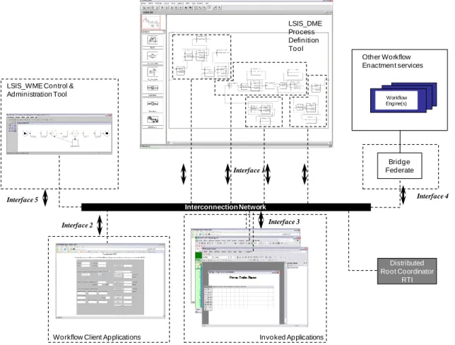
We demonstrated in [20] and [21] that G-DEVS models can be run from several computers thanks to the capability of LSIS_DME to create HLA federates. This capability matches with the distribution requirements of the actual industrial pro-cesses. Thus, we have implemented the flattened G-DEVS simulation structure presented in this paper and its HLA com-pliance detailed in [22] as the run time engine of a new dis-tributed Workflow environment. Then, the key is to generalize the HLA compliance to the whole Workflow environment by adding other federates to the federation in order to define a Distributed Workflow Reference Model in terms of WfMC. The resulting platform is described in Fig. 14. We note that the
flattened hierarchy of G-DEVS models joining the federation are coherently synchronized in the context of HLA distributed execution, all other federates connected to the RTI also need to implement a synchronization algorithm.
Therefore, we included the Workflow modelling tool LSIS_WME presented in Fig. 11 (developed at LSIS) into a federate (i.e. Fig. 13 Interface 5). The models defined in XML generated by this federate are integrated into HLA objects and shared with LSIS_DME (Fig. 13 interface 1).
In detail, LSIS_WME publishes to HLA objects that repre-sent the components of the Workflow model and to which LSIS_DME subscribes. These objects are stored in the Work-flow federation FOM. The updates of information are routed by the RTI. If the Workflow model is modified by the user of LSIS_WME, LSIS_DME is informed of these changes. It can take them into account in its G-DEVS model and reruns the simulation with the new coupled model structure and new atomic models edited settings (DEVS expert users can also access directly to advanced DEVS editing facilities on LSIS_DME models fig 13. Interface 1). On the other hand, during the simulation, LSIS_DME updates, in an HLA object, the log of events results of simulation. LSIS_WME subscribes to these results to give the simulation animation and results updates to the users. For this reason, this software can be seen as the modelling, control, and administration tool of the Work-flow environment.
Fig. 14. Workflow G-DEVS/HLA M&S platform
Interoperability is a core concern of the networked enter- prise [26]; this platform addresses this requirement by propos-Interface 1
Interface 4 Interface 5
Workflow Client Applications
Interface 3 Interface 2 Invoked Applications Other Workflow Enactment services Workflow Engine(s) Distributed Root Coordinator RTI Interconnection Network LSIS_DME Process Definition Tool Bridge Federate
LSIS_WME Control & Administration Tool
ing an open standard interface (thank to the HLA compliance) to plug other software components. In more detail, the HLA capability to integrate programs without recoding facilitates the needs of today’s flexible enterprise that needs to interoper-ate its Information Systems and to communicinteroper-ate in a distribut-ed networkdistribut-ed environment.
Indeed, software and humans acting in the loop are required in the existing Workflow process of wafer manufacturing. At the end, we address the Workflow definitions [10], where client and invoked applications can be called during the run time in order to process computations not tackled by the mod-els and their simulators. Details are given below.
On one hand, we have proposed to integrate humans in the loop to make qualitative choices during simulation. For that purpose, we implemented Web interfaces called during the simulation by the Workflow engine in order to specify, for instance, some routing of items in the process. Data exchanged during the call are HLA objects (i.e. Fig. 13 interface 2).
On the other hand, some complex mathematical computa-tions of data handling (e.g. access to a specific databases, specific software use, etc.) are not taken into account in transi-tion/output functions of the G-DEVS model described with LSIS_DME. In that case the simulation is interrupted and data are transferred to specific software by publishing to an object (i.e. Fig. 13 interface 3). This software computes and sends back data to the process definition tool by publishing to HLA objects/interaction.
Concretely, we have implemented and tested the platform described in Fig. 13, in the context of microelectronics manu-facturing. It actually contains a LSIS_WME model editor and control viewer of the execution, one LSIS_DME M&S tool to simulate the process, several MS Excel databases, Java based user interfaces for microelectronic quality control, and Java software called to automatically store the time duration and stock levels. The distributed simulation results obtained on the platform has been confronted to expert knowledge for valida-tion.
Finally, we also open to interfacing, in term of data interop-erability, the environment with other Workflow environments using the concept of bridges federates [30] (i.e. Fig. 13 inter-face 4). The structure of the information exchange is HLA specified and information can be easily shared with respect to the confidentiality definition of publishing and subscribing rights for data. In this last interfacing, each time we create a new connection with another workflow system, we should determine the data which should be shared and the ones that must stay confidential between Workflows. Concretely the two workflows will be two HLA federates in a new federation and the users will need to define the HLA objects to be ex-changed between federates.
A. Environment Future Works
The complete development of the proposed environment still requires the addition of other clients and invoked applica-tions to the Workflow environment by integrating them in HLA federates. We plan to integrate other heterogeneous tools developed in the specific context of STMicroelectronics by
adding code to them to make them HLA compliant. In addi-tion, we have initiated works on interoperability of infor-mation systems of enterprises. In these works, we are propos-ing ontological mapppropos-ing of the business knowledge. HLA is helping to manage the exchange of information between het-erogeneous and distributed enterprise systems interconnected as a System of Systems. These works are detailed in [5].
Furthermore, domain experts often define Workflow task durations in terms of time windows rather than mean values. Thus, it would be possible to model Workflow with Min-Max DEVS to get more realistic models [31].
IV. CONCLUSION
This paper presented a flattened G-DEVS model simulation structure. It detailed the flattening transformation algorithm involved in LSIS_DME. We have performed comprehensive tests on the LSIS_DME flattened simulator. The results reveal that the flattening of the simulation structure shortened the simulation duration. However, the efficiency of the flattening remains depending on the number of events handled and the complexity of the model. As perspectives, we will propose to divide the event list into several lists, to distinguish events in near occurrence time and far future. Such heuristics, that has shown their efficiency in scheduling problem solving, should reduce considerably the size of the event lists and improve sorting each time an occurred event should be handled in this list. Also, to prove the efficiency of the flatten simulator with regard to the hierarchical one, we could compute the algorith-mic complexity of each simulator. Knowing that to conduct simulation on computer, we should formally estimate the heap memory and the execution time of each technique (flattened, hierarchical). This will be possible by giving a detailed study on the computational complexity of the used algorithms and data structure of the simulation (sort events, number of coor-dinators, number of event lists that depends on the number of coordinator, etc.).
We proposed to employ the new flattened structure for sim-ulating complex Workflows models in G-DEVS formalism. Consequently, GDEVS Workflows models can be verified faster by simulation. Furthermore, we introduced a new HLA compliant Workflow environment using the flattened G-DEVS structure that speeds the local execution and so orches-trates faster the distributed components. We verified, on this occasion, that the use of the HLA specification facilitates connecting the G-DEVS components defined in the paper with other heterogeneous HLA compliant components in the Work-flow environment.
Finally, the application field of researches on Workflow and, more generally, process modelling has been a fast grow-ing research domain durgrow-ing recent years, and it is still a prom-ising domain in particular for service orchestration in the en-terprise. The European International Virtual Laboratory for Enterprise Interoperability [32] has recently defined the in-teroperability as a science for enterprise modelling; it confirms the actual high interest of enterprises for distributed and in-teroperable information systems solutions (systems of
sys-tems, enterprise 2.0). We believe the crossing of research domains: Workflow M&S and HLA will facilitate supporting the next generation of information systems for interoperating networked enterprises.
REFERENCES
[1] Zeigler, B.P., H. Praehofer, and T. G. Kim. 2000. Theory of Modeling
and Simulation. 2nd edition, Academic Press, New York, USA.
[2] Giambiasi, N., B. Escude, and S. Ghosh. 2000. “G-DEVS A General-ized Discrete event specification for accurate modeling of dynamic sys-tems”, Transactions of the SCS International, 17, 3: 120–134. [3] Courtois, T. 1996. “Workflow: la gestion globale des processus”,
Logiciels & Systèmes, 11 (Sept.): 46–50.
[4] Zacharewicz, G., Hamri, A., Trojet, W., Frydman, C., and Giambiasi, N. 2006. “G-DEVS/HLA Environment for Distributed Simulations of Workflows”, invited talk in International Conference on Modeling and
Simulation - Methodology, Tools, Software Applications (M&S-MTSA'06), Calgary, Alberta, Canada.
[5] Zacharewicz, G., D. Chen, and B. Vallespir. 2009. “Short-lived ontolo-gy approach for agent/HLA federated enterprise interoperability Inter-national”, In IEEE proceedings of international Conference I-ESA
Chi-na 2009 Interoperability for Enterprise Software and Applications,
p.329-335, Beijing, 22–23 April.
[6] Kim, K., W. Kang, B. Sagong, and H. Seo. 2000. “Efficient distributed simulation of hierarchical DEVS models: transforming model structure into a non-hierarchical one”, in 33rd Annual Simulation Symposium, Washington, D.C., p. 227.
[7] Glinsky, E. and G.A. Wainer. 2005. “DEVStone: a benchmarking technique for studying performance of devs modeling and simulation environments”, 9th IEEE International Symposium on Distributed
Sim-ulation and Real Time Applications (Montreal, Canada).
[8] IEEE Institute of Electrical and Electronic Engineers. 2001. “High Level Architecture (HLA) – Federate Interface Specification” IEEE Standard for Modeling and Simulation (M&S). std 1516.2-2000, March.
[9] Fujimoto, R.M. 1998, “Time management in the high level architec-ture”, Trans. of SCS, Simulation, 71, 6 (Dec): 388–400.
[10] WfMC Workflow Management Coalition. 1999. Terminology &
Glos-sary. WfMC-TC-1011, 3.0, Feb.
[11] WfMC Workflow Management Coalition. 2005. Workflow Process
Definition Interface - XML Process Definition Language.
WFMC-TC-1025, Oct.
[12] Van Hee, K., R. Post and L. Somers. 2005. “Yet another smart process editor”, ESM 2005, Porto, 24–26 Oct.
[13] Russell, N., A.H.M. ter Hofstede, D. Edmond, and W.M.P. van der Aalst. 2004. “Workflow data patterns”, QUT technical report, FIT-TR-2004-01, Queensland University of Technology, Brisbane.
[14] Weisel, E.W., M.D. Petty, and R.R. Mielke. 2005. “A comparison of DEVS and semantic composability theory”, Proceedings of the Spring
2005 Simulation Interoperability Workshop, San Diego CA, 3–8 April,
pp. 956–964.
[15] Hamri, M, Zacharewicz, G. 2007 “LSIS_DME: An Environment for Mod-eling and Simulation of DEVS Specifications” 14th Conference
on Simulation and Planning in High Autonomous systems, Buenos
Aires, pp.55-60.
[16] Wainer, G. Listing of M&S tools based on the DEVS formalism web-site. http://www.sce.carleton.ca/faculty/wainer/standard/tools.htm, cre-ated November 2005, accessed Apr 2009.
[17] Drost, J. 2001. ShiftOne JRat (Runtime Analysis Toolkit), Logiciel GNU, http://jrat.sourceforge.net/
[18] Giambiasi, N., Miara, A. and Muriach, D., SILOG: A Practical Tool for Large Digital Net-work Simulation. in 16th Annual ACM IEEE
Confer-ence on Design Automation, (San Diego, USA, 1979), IEEE Press,
263-271.
[19] Miara, A. and Giambiasi, N., Dynamic and deductive fault simulation. in Proceedings of the 15th Conference on Design Automation
Confer-ence, (Las Vegas, Nevada, USA, 1978), IEEE Press, 439 - 443.
[20] Zacharewicz, G., N. Giambiasi and C. Frydman. 2005. “Improving the DEVS/HLA Environment”, in DEVS Integrative M&S Symposium,
DEVS'05, Part of the SCS Spring-Sim'05, San Diego, USA, 3–7 Apr.
[21] Zacharewicz G., N. Giambiasi, and C. Frydman. 2006b. “Lookahead computation in G-DEVS/HLA environment”, Simulation News Europe
Journal (SNE) special issue 1 “Parallel and Distributed Simulation
Methods and Environments”, 16, 2 (Sept.): 15–24.
[22] Zacharewicz, G., C. Frydman and N. Giambiasi, 2008 “G-DEVS/HLA Environment for Distributed Simulations of Workflows”, Transactions of the SCS, Simulation, Vol. 84, No. 5, pp.197-213.
[23] Van der Aalst, W.M.P., A.H.M. ter Hofstede, B. Kiepuszewski, and A.P. Barros. 2000. “Advanced workflow patterns”, in O. Etzion and P. Scheuermann, editors, 7th International Conference on Cooperative
In-formation Systems (CoopIS 2000), Lecture Notes in Computer Science,
vol. 1901, Springer-Verlag, Berlin, pp. 18–29.
[24] Van der Aalst, W.M.P., and K.M. van Hee. 2002. Workflow
Manage-ment: Models, Methods, and Systems. MIT press, Cambridge, MA.
[25] Seck, M., N. Giambiasi, C. Frydman, L. Baâti, 2007. “DEVS For Human Behavior Modelling in CGFs”, Journal of Defense Modeling
and Simulation (JDMS), 4, 3 (July) 1-33.
[26] Chen, D., and G. Doumeingts. 2003. “European initiatives to develop interoperability of enterprise applications – basic concepts, framework and roadmap”, Journal of Annual Reviews in Control, 7, 2: 151–160. [27] OMG (Object Management Group). 2003. “MDA Guide Version
1.0.1”, Document number: omg/20030601.
[28] Bourey, J.P., R. Grangel Seguer, G. Doumeingts, and A.J. Berre. 2007. “Report on model driven interoperability”, deliverable DTG2.3, INTEROP NoE (Apr.), p. 91
[29] IEEE Institute of Electrical and Electronic Engineers. 2000, -. “IEEE Standard for Mode-ling and Simulation (M&S) High Level Architec-ture (HLA) - Federate Interface Specification”. IEEE Standard for Modeling and Simulation (M&S). std 1516.2
[30] Bréholée, B., and P. Siron. 2003. “Design and implementation of a HLA inter-federation bridge”, in Proceedings of the EUROSIW, Stock-holm, Sweden, 16–19 June.
[31] Hamri M., N. Giambiasi and C. Frydman. 2006 “Min-Max DEVS Modeling and Simulation”. Simulation Practice and Theory, 14: 909– 929
[32] V-LAB, http://interop-vlab.eu/the-scientific-activities, created Decem-ber 2007, accessed Apr 2009.
Gregory Zacharewicz is Associate Professor in Bordeaux
1 University (IUT MP). His research interests include DEVS, G-DEVS, Distributed Simulation, HLA, and Workflow. He recently focussed on Enterprise Modelling and Interoperabil-ity.
www.ims-bordeaux.fr/IMS/pages/pageAccueilPerso.php?email=gregory.zacharewicz
Maâmar El-Amine HAMRI is Associate Professor in Paul
Cézanne University of Marseille. He conducts his research at LSIS laboratory. He is interested in DEVS, its extensions and software developments for discrete event modeling and simu-lation.
http://www.lsis.org/~maamar_el-amine_hamri.html
Claudia Frydman is full Professor in Paul Cézanne
Uni-versity of Marseille. She has been active for many years in knowledge management and currently her re-search is focus-ing especially on researches on knowledge based simulation.
http://www.lsis.org/~claudia_frydman.html
Norbert Giambiasi is full Professor in Paul Cézanne
Uni-versity of Marseille and Director of LSIS (Laboratory of In-formation Sciences and Systems). He has been active for many years in simulation and currently his research is focus-ing especially on DEVS and relative developments.