HAL Id: tel-02124658
https://tel.archives-ouvertes.fr/tel-02124658
Submitted on 9 May 2019
HAL is a multi-disciplinary open access
archive for the deposit and dissemination of sci-entific research documents, whether they are pub-lished or not. The documents may come from teaching and research institutions in France or abroad, or from public or private research centers.
L’archive ouverte pluridisciplinaire HAL, est destinée au dépôt et à la diffusion de documents scientifiques de niveau recherche, publiés ou non, émanant des établissements d’enseignement et de recherche français ou étrangers, des laboratoires publics ou privés.
Analysis of a methane/air flame propagating in a
two-dimensional small-scale channel with consideration
of the conjugate heat transfer
Kevin Bioche
To cite this version:
Kevin Bioche. Analysis of a methane/air flame propagating in a two-dimensional small-scale channel with consideration of the conjugate heat transfer. Fluids mechanics [physics.class-ph]. Normandie Université, 2018. English. �NNT : 2018NORMIR25�. �tel-02124658�
TH `
ESE
Pour obtenir le diplˆome de doctorat
Sp´ecialit´e M´ecanique des Fluides Pr´epar´ee `a l’INSA Rouen Normandie
A
NALYSE DE LA PROPAGATION D
’
UNE FLAMME
M
ETHANE
´
/
AIR DANS UN CANAL
ETROIT
´
BI
-
DIMENSIONNEL AVEC PRISE EN COMPTE DES
COUPLAGES THERMIQUES
pr´esent´ee et soutenue par
K ´
EVINBIOCHE
Th`ese soutenue publiquement le 27 Novembre 2018 devant le jury compos´e de
G. DAYMA Professeur `a l’Universit´e d’Orl´eans, ICARE-CNRS Rapporteur B. DENET Professeur `a l’Universit´e d’Aix-Marseille, IRPHE-CNRS Rapporteur P. GARCIA-YBARRA Professeur `a l’Universit´e Nationale d’ ´Education `a
Dis-tance de Madrid
Examinateur F. RICHECOEUR Professeur `a l’ ´Ecole CentraleSupelec, EM2C-CNRS Examinateur P. DOMINGO Directrice de Recherche, CORIA-CNRS Examinateur G. RIBERT Maˆıtre de Conf´erences `a l’INSA Rouen Normandie,
CORIA-CNRS
Directeur de th`ese L. VERVISCH Professeur `a l’INSA Rouen Normandie, CORIA-CNRS Co-Directeur de th`ese
3
R´esum´e : Analyse de la propagation d’une flamme m´ethane-air dans un canal ´etroit bi-dimensionnel avec prise en compte des couplages thermiques
La stabilisation et la propagation d’une flamme laminaire pr´e-m´elang´ee m´ethane/air dans un canal ´etroit, sont revisit´ees `a partir de simulations num´eriques. La combustion est mod´elis´ee `a l’aide d’une chimie et de propri´et´es de transport complexes, ainsi que du couplage des trans-ferts thermiques `a l’interface et dans les parois. Premi`erement, une proc´edure de r´eduction des m´ecanismes chimiques adapt´ee `a cette application est mise en œuvre. Deuxi`emement, la r´eponse de la forme de flamme, lorsque soumise `a diverses conditions thermiques, est analys´ee en termes de vitesse de propagation et de topologie de l’´ecoulement au voisinage du front de r´eaction. Troisi`emement, le m´ecanisme de transfert thermique d´eclenchant la propagation de flamme lorsque celle-ci est soumise `a un pr´echauffage est montr´e ˆetre principalement convectif. Pour finir, le rˆole pr´epond´erant de la gravit´e, via l’action du moment barocline, sur l’asym´etrie des flammes se propageant dans des canaux ´etroits, est d´emontr´e.
Mots-cl´es : simulation num´erique directe de la combustion, ´ecoulements laminaires, trans-ferts flamme-paroi, combustion `a petite ´echelle, r´eduction de sch´ema cin´etique
Abstract: Analysis of methane-air flame propagation in a narrow channel with conjugate heat transfer accounting
The flow physics controlling the stabilization and propagation of a methane/air laminar premixed flame in a narrow channel is revisited from numerical simulations. Combustion is described with complex chemistry and transport properties, along with a coupled simulation of heat transfer at and within the wall. First, a chemistry mechanism reduction procedure fitted to this application is applied. Second, the response of the premixed flame shape to various heat transfer conditions is analysed in terms of flame propagation velocity and flow topology in the vicinity of the reactive front. Third, the heat transfer mechanism triggering the flame movement when this last is submitted to an upstream wall preheating is revealed to be mainly convective. To finish, the preponderant role of gravity, via an impact on the baroclinic torque, in the sym-metry breaking of small-scale channel flames is demonstrated.
Keywords: direct numerical simulation of combustion, laminar flows, flame-wall transfers, small-scale combustion, kinetic mechanism reduction
Remerciement
Mes travaux de th`ese sont le fruit d’un travail personnel mais aussi de nombreuses interactions, je tiens ici `a remercier les personnes qui ont compt´e dans leur accomplissement.
Je remercie les membres de mon jury, Guillaume Dayma, Bruno Denet, Pedro Garcia-Ybarra, Frank Richecoeur et Pascale Domingo pour le temps consacr´e `a la lecture de mon manuscrit ainsi que les commentaires enrichissants formul´es et discut´es lors de ma soutenance. Cette th`ese, financ´ee par l’Agence National de la Recherche dans le cadre du projet ANR-14-CE05-0030-MAPEE: ‘Microcombustion Assist´ee par Plasma et Exc`es d’Enthalpie’, et a ´et´e men´ee au sein du laboratoire CORIA. Je remercie ses directeurs successifs, Mourad Boukhalfa et Armelle Cessou de m’avoir accueilli dans leurs locaux.
Je remercie chaleureusement mes directeurs de th`ese, Guillaume Ribert et Luc Vervisch, de m’avoir encadr´e et fait confiance pour ce projet. Merci pour votre investissement par-ticuli`erement remarquable dans l’ensemble de mes travaux, votre disponibilit´e et le plaisir que vous mettez `a discuter de science. Merci de m’avoir montr´e comment communiquer des r´esultats scientifiques, et merci de votre approche positive.
Je remercie les autres permanents de l’´equipe: Ghislain, pour les conseils et le support info au top du top; Vincent, pour les discussions scientifiques int´eressantes et Guido pour les ´echanges sur les m´ethodes pseudo-spectrales.
Merci aux anciens, partis trop tˆot `a mon avis (trop tard au leur peut-ˆetre). Bastien (en parlant de tard) pour ton guidage lors de mes premiers pas avec SiTCom. JB pour nos sessions musi-cales saveur stoner. Umut pour tes citations complexes, voire abyssales mais toujours pleines de fraicheur, qui ont d´efinitivement marqu´e le bureau. Loic pour tes g´en´ereuses gamelles-traiteurs (j’admets que le tofu c’est bon en fait). Pierre pour l’accueil en territoire hostile bas-Normand. Nico L. et Yann pour les soir´ees Halloween et les sorties au bar, ce toujours en concervant un certain standing (voir un standing incertain). Nico J. pour les soir´ees `a la coloc et la rhythm guitar. Dorian, ”franchement je reste une demie-heure, ma copine m’attend `a l’appart”, merci pour c¸a entre autres. Eurielle pour ta bonne humeur. Geogeo l’affreux, ah mais qu’est-ce que tu es affreux... Alex pour les discussions qui ´el`event le niveau, et les ca¨ıpi qui l’abaissent. Francis pour la bricole et les jeux du dimanche. Andr´ea pour les ´echanges musicaux. Patricia pour
Remerciement 6
les cours linguistiques. Felix, Romain, Hakim et Lancelot pour les pauses et sorties en ville. Deewakar, Huu-tri et Camille pour la bonne prise en main de l’ambiance du bureau.
Merci `a DD, la Petite Dure, Gourmandine et Digiaud pour les moments d´econtract´es qui font relativiser quand l’un a mal `a sa douleur. Ce fut bon d’ˆetre un Flanders parmis vous pen-dant ce d´ebut de th`ese.
Merci aux copains de longue date, voir de toujours. Que l’on ne se quitte jamais.
Merci `a mon fr`ere, ma soeur, mes parents et Peluche pour leur soutien qui rechauffe le coeur. Jack, merci pour la compagnie (`a peine envahissante) pendant la r´edaction.
Contents
1 Introduction 19
1.1 Chapter summary . . . 19
1.2 Context of the micro-combustion study. . . 20
1.2.1 Industrial context: The miniaturisation race . . . 20
1.2.2 Limits of miniaturisation: The power source. . . 20
1.2.3 Small-scale combustion as a solution and first achievements . . . 22
1.3 State of the art . . . 23
1.3.1 Definitions . . . 23
1.3.2 Micro-combustion specificities . . . 24
1.3.2.1 Thermal quenching . . . 24
1.3.2.2 Radical quenching . . . 25
1.3.2.3 Diffusion dominated flows . . . 27
1.3.3 Micro-combustion modelling background . . . 28
1.3.3.1 Heat loss modelling . . . 28
1.3.3.2 Surface reactions modelling . . . 29
1.3.3.3 Kinetic mechanism choices . . . 31
1.3.3.4 Soret effect. . . 31
1.3.3.5 Multi-dimensional property of the simulations . . . 32
1.3.3.6 Symmetric and asymmetric flame topologies . . . 32
1.3.3.7 Gravity effect . . . 35
1.3.3.8 Unsteady modes . . . 36
1.3.3.9 Flame front tracking in numerical simulations . . . 36
1.3.4 Managing small-scale combustion . . . 36
1.3.4.1 Excess enthalpy . . . 37
1.3.4.2 Catalytic combustion . . . 38
1.4 Ph. D. thesis objectives and outline . . . 40
1.5 Publications . . . 43
1.5.1 Peer-reviewed international journals . . . 43
1.5.2 Conferences. . . 43
2 Modelling 45 2.1 Chapter summary . . . 45
CONTENTS 9 2.2 Aerothermochemistry equations . . . 46 2.2.1 Mixture properties . . . 46 2.2.2 Balance equations . . . 47 2.2.2.1 Conservation of momentum . . . 47 2.2.2.2 Conservation of mass . . . 47
2.2.2.3 Conservation of total sensible energy . . . 49
2.2.2.4 Species source term computation . . . 49
2.2.3 Dimensionless numbers . . . 50
2.3 Solid/flow conjugate heat transfer: A solid solver . . . 51
2.3.1 Conservation of energy . . . 52
2.3.2 Numerical resolution . . . 53
2.3.3 Imposition of the boundary conditions . . . 55
2.3.4 Coupling strategy . . . 55
2.3.5 Validation . . . 57
2.3.5.1 Mono-dimensional semi-infinite flat plate. . . 57
2.3.5.2 Three-dimensional diffusion of a Dirac peak . . . 58
2.3.5.3 Infinitely Fast Flame test case . . . 59
2.4 Numerical solving with SiTCom-B . . . 60
2.4.1 Numerical methods . . . 60
2.4.1.1 Space and time integration . . . 60
2.4.1.2 Artificial viscosity . . . 60
2.4.1.3 Boundary conditions. . . 62
2.4.1.4 Kinetics and transport modelling . . . 62
2.4.1.5 Energy equation resolution in the solid . . . 62
2.4.2 Simulations parameters . . . 63
2.4.2.1 Domain dimensions . . . 63
2.4.2.2 Mesh resolution . . . 63
2.4.2.3 Temporal advancement restriction. . . 63
2.4.2.4 Wall characteristics and coupling with the flow solver . . . . 65
2.4.2.5 Inlet velocity profile . . . 65
2.4.3 Numerically stabilizing flames in channels . . . 66
3 Kinetic mechanism reduction strategy for small-scale combustion 69 3.1 Preamble . . . 69
3.2 Introduction . . . 70
3.3 Optimised and Reduced Chemistry: ORCh method . . . 70
3.4 Reduction trajectories for small-scale combustion . . . 71
3.5 Results on canonical problems . . . 74
3.5.1 1D premixed flames with and without uniform heat loss . . . 74
3.5.2 Auto-ignition delays . . . 79
3.6 Results on the 2D case of a flame propagating in a small-scale channel . . . 80
CONTENTS 10
4 Premixed flame/wall interaction in a narrow channel under microgravity: Impact
of wall thermal conductivity and heat losses 85
4.1 Introduction . . . 86
4.2 Configuration . . . 86
4.3 Analysis of the burning velocity . . . 90
4.3.1 Observations . . . 90
4.3.2 Scaling law . . . 91
4.4 Effect of the sheared flow . . . 93
4.4.1 Quenching . . . 93
4.4.2 Flow deviation . . . 93
4.4.3 Kinetics . . . 95
4.5 Thermal coupling influence . . . 97
4.5.1 Heat transfer at the wall . . . 97
4.5.2 Flow deviation . . . 98
4.5.3 Energy budget on the thermally coupled flame . . . 99
4.5.4 Kinetics . . . 101
4.6 Flame response to wall heat transfer properties in a regime diagram . . . 103
4.6.1 Asymptotic behaviours . . . 103
4.6.2 Competition of the influence of conductivity and convection on the flame characteristics . . . 105
5 Simulating upstream flame propagation in a narrow channel after wall preheating under microgravity 108 5.1 Introduction . . . 108
5.2 Configuration . . . 109
5.2.1 Numerics . . . 109
5.2.2 Heating scenario . . . 110
5.3 Downstream movement by fresh gases dilatation . . . 113
5.4 Flame acceleration from convective heat transfer . . . 114
5.5 Flame translation and final position. . . 116
6 The role of gravity and external heating in the asymmetry of flames stabilized in a narrow combustion chamber 120 6.1 Introduction . . . 120
6.2 Experimental and numerical set-up . . . 121
6.2.1 Experimental configuration. . . 121
6.2.2 Numerical set-up . . . 122
6.3 Analysis of gravity effects . . . 123
6.3.1 Case (i): Flame stabilised with heat-conductive wall . . . 123
6.3.2 Case (ii): Flame propagating over a quasi-isothermal wall . . . 125
CONTENTS 11
6.4 Influence of external heating and channel dimensions on the stability of
sym-metric flame topologies . . . 132
7 Conclusion and perspectives 137 7.1 Chapter summary . . . 137
7.2 Conclusion . . . 137
7.2.1 Chemistry modelling . . . 138
7.2.2 Flame/wall interactions . . . 139
7.2.3 Flame response to upstream heating . . . 140
7.2.4 Role of the gravity in the breaking of flame symmetry . . . 140
7.3 Perspectives . . . 141
7.3.1 On-earth intricate boundary layer, heat recirculation and flame coupling 141 7.3.2 Experimental comparisons . . . 141
7.3.3 Low temperature chemistry . . . 141
7.3.4 Thermally optimised and catalytic burners . . . 142
A Reduced mechanisms for small-scale combustion at φ = 0.8 and φ = 0.7 144 A.1 17S-53R-0.8 mechanism assessment . . . 147
A.1.1 Flame speed . . . 147
A.1.2 Auto-ignition delays . . . 147
A.1.3 1D flame profiles . . . 147
A.2 17S-53R-0.7 mechanism assessment . . . 151
A.2.1 Flame speed . . . 151
A.2.2 Auto-ignition delays . . . 151
A.2.3 1D flame profiles . . . 151
B Meshing for DNS 156 B.1 15S-26R . . . 156
B.2 17S-53R-1.0 . . . 159
B.3 GRI-1.2 . . . 162
C Equivalence ratio influence on the flame topology 166 C.1 Under microgravity . . . 166
C.2 Under the gravitational field of the earth . . . 167
Nomenclature
Abbreviations
Symbol Description
ANR Agence Nationale de la Recherche
CFD Computational Fluid Dynamics
CNC Computer Numerical Control
CNRS Centre National de la Recherche Scientifique
CORIA COmplexe de Recherche Interprofessionel en Aerothermochimie
CPU Central Processing Unit
DNS Direct Numerical Simulation
DRGEP Directed Relation Graph with Error Propagation
D-L Darrieus-Landau
D-T Diffusive-Thermal
EDM Electro-Discharge Machining
EM2C Energ´etique Mol´eculaire et Macroscopique, Combustion
GPS Global Positioning System
FREI Flame Repetitive Extinction Ignition
GRI Gas Research Institute
IBM Ion Beam Machining
INSA Institut National des Sciences Appliqu´ees
LBM Laser Beam Machining
MEMS Micro-Electro-Mechanical Systems
MIT Massachusetts Institute of Technology
MPI Message Passing Interface
NASA National Aeronautics and Space Administration
NSCBC Navier-Stokes Characteristic Boundary Condition
Nomenclature 14
ORCh Optimised and Reduced Chemistry
QSS Quasi-Steady State
RK Runge-Kutta
R-T Rayleigh-Taylor
SCTP Standard Conditions for Temperature and Pressure
SiTCom-B Simulation of Turbulent Combustion with Billion of points
S-T Saffman-Taylor
Roman letters
Symbol Description Unit
Aj Pre-exponential factor of the Arrhenius law for reaction j variable
Af,j Forward pexponential factor of the Arrhenius law for
re-action j
variable
Ab,j Backward pre-exponential factor of the Arrhenius law for
reaction j
variable
b Thermal effusivity J.m−2.K−1.s−12
c Speed of sound m.s−1
Cp Specific heat capacity at constant pressure J.kg−1.K−1
Cp,k Specific heat capacity of species k at constant pressure J.kg−1.K−1
Cv,k Specific heat capacity of species k at constant volume J.kg−1.K−1
CF L Courant-Friedrichs-Lewy number
-Chem Chemical time step restriction number
-Dk Diffusion coefficient of species k m2.s−1
Dk,j Binary diffusion coefficient of species k into species j m2.s−1
E Specific total sensible or non-chemical energy J.kg−1
Ea,j Molecular activation energy of reaction j J.mol−1
F o Fourier number
-h Convective heat transfer coefficient W.m−2.K−1
hk Specific enthalpy of species k J.kg−1
hsk Specific sensible enthalpy of species k J.kg−1
hok Specific enthalpy of formation of species k J.kg−1
jk Diffusive mass flux kg.m−2.s−1
kw Wall heat transfer coefficient inside the channel W.m−2.K−1
Nomenclature 15
Kb,j Backward chemical constant of reaction j variable
`c Characteristic length m
`e External channel height m
`i Internal channel height m
Mk Formula of species k
-m Overall mass contained in the control volume V kg
mk Mass of species k contained in the control volume V kg
n Overall moles contained in the control volume V mol
nk Moles of species k contained in the control volume V mol
Nr Number of reactions
-Nsp Number of species
-Nvar Number of transported variables
-P Pressure Pa
Qj Reaction rate of reaction j mol.m−3.s−1
Qf,j Forward reaction rate of reaction j mol.m−3.s−1
Qb,j Backward reaction rate of reaction j mol.m−3.s−1
r Reduced ideal gas constant J.kg−1.K−1
R Ideal gas constant J.mol−1.K−1
SL Flame burning velocity m.s−1
T Temperature K
u Velocity vector m.s−1
u Velocity in the x direction m.s−1
v Velocity in the y direction m.s−1
V Control volume m3
Vc,j Correction velocity of species k m.s−1
Vk,j Molecular diffusion velocity of the k-th species in the j-th
direction
m.s−1
w Velocity in the z direction m.s−1
W Molecular weight of the mixture kg.mol−1
Wk Molecular weight of species k kg.mol−1
Xk Molecular fraction of species k
-[Xk] Molecular concentration of species k mol.m−3
Y Species mass fraction vector containing the mass fractions
of the Nsp species
-Nomenclature 16
YC Progress variable
-YF Mass fraction of fuel
-Yk Mass fraction of species k
-YOx Mass fraction of oxidizer
-Greek letters
Symbol Description Unit
α Thermal diffusion coefficient m2.s−1
αloss Heat loss coefficient W.m−3.K−1
βj Temperature exponent of the Arrhenius law for reaction j
-δ Kronecker tensor
-δF Flame thickness m
δt Time step s
δtC Convective time step s
δtCh Chemical time step s
δtD Diffusive time step s
δx Cell size in the direction x m
∆Hjo Molecular enthalpy change when passing from reactants to
products in reaction j
J.mol−1
∆Sjo Molecular entropy change when passing from reactants to
products in reaction j
J.mol−1.K−1
ε Radiative emission coefficient
-λ Thermal conductivity W.m−1.K−1
λk Thermal conductivity of pure species k W.m−1.K−1
µ Dynamic viscosity kg.m−1.s−1
µk Dynamic viscosity of pure species k kg.m−1.s−1
ν Kinematic viscosity j m2.s−1
νk,j Stoichiometric coefficient of species k in reaction j
-νk,j0 Reactant stoichiometric coefficient of species k in reaction
j
-νk,j00 Product stoichiometric coefficient of species k in reaction j
-ρ Density kg.m−3
˙
ωk Chemical source term of species k kg.m−3.s−1
˙
Nomenclature 17
˙
ωρYk Chemical source term of species k kg.m
−3.s−1
˙
ωρE Heat release source term W.m−3
φ Equivalence ratio
-σ Stefan-Boltzmann constant W.m−2.K−4
τ Newtonian viscous tensor kg.m−1.s−2
τconv Convection characteristic time s
τchem Chemical characteristic time s
τdiff Diffusion characteristic time s
τign Auto-ignition delay s
Non dimensional numbers
Symbol Description
Da Damk¨ohler number
Fr Froude number
Lek Lewis number associated to species k
Nu Nusselt number
Pe P´eclet number
Re Reynolds number
Superscript and subscript
Symbol Description o Adiabatic f Fluid F Flame s Solid st Stoichiometric w Wall
Chapter 1
Introduction
Contents
1.1 Chapter summary . . . 19
1.2 Context of the micro-combustion study . . . 20
1.2.1 Industrial context: The miniaturisation race . . . 20
1.2.2 Limits of miniaturisation: The power source. . . 20
1.2.3 Small-scale combustion as a solution and first achievements . . . 22
1.3 State of the art . . . 23
1.3.1 Definitions . . . 23
1.3.2 Micro-combustion specificities . . . 24
1.3.3 Micro-combustion modelling background . . . 28
1.3.4 Managing small-scale combustion . . . 36
1.4 Ph. D. thesis objectives and outline . . . 40
1.5 Publications . . . 43
1.5.1 Peer-reviewed international journals . . . 43
1.5.2 Conferences. . . 43
1.1
Chapter summary
Section 1.2 gives a picture of the industrial and technological context of the young micro-combustion field. The recent trend to miniaturise the electrical power sources is depicted in subsection1.2.1while subsection1.2.2presents the limits of this technology. Subsection1.2.3
shows that combustion is evoked as an alternative to electrical batteries for embedded low power sources and presents the first technological achievements made by the community in this area.
Section 1.3 is the opportunity to give an overview on the former and ongoing research work on small-scale combustion. First, in subsection 1.3.1, the various definitions for micro-combustion encountered in the literature are recalled and discussed to introduce the present
Introduction 20
study framework. Second, subsection 1.3.2evokes the physics specificities of combustion at small scales. In subsection1.3.3an overview of the common modelling strategies is then given with a special attention paid to the analytical and numerical assumptions made in the approach of the physics. The propositions brought by the community to manage this new combustion technology are then presented in subsection 1.3.4. Finally, the Ph. D. thesis objectives are presented and placed within this state of the art in section1.4 and the communications issued from this work are listed in section1.5.
1.2
Context of the micro-combustion study
1.2.1
Industrial context: The miniaturisation race
The last decades have been marked by research and industrial efforts in the field of miniatur-isation. The recent deep changes in the consumers habits, with the entry in private life of a multitude of portable devices such as the cellular phones, the laptops or the GPS technologies, motivated the downsizing and the weight reduction of electronic devices. In addition, tech-nical fields such as biomedicine or molecular biology, also took advantage of miniaturisation for applications such as the conception of micro-grippers used to manipulate organic cells or tissues [39], or the fabrication of bio-sensors used in the detection of virus [74]. The need for downsizing, issued by these recent applications, motivated the development of small-scale fabrication technologies. Among the current techniques one can count the Electro-Discharge Machining (EDM), the Laser Beam Machining (LBM) and the Ion Beam Machining (IBM) permitting to assemble the so-called Micro-Electro-Mechanical Systems (MEMS). These tech-nologies have been employed with success to decrease dramatically the size of all types of components, from gas separation column of portable chromatograph used in the detection of hazardous gases [56] to inkjet print heads.
1.2.2
Limits of miniaturisation: The power source
In the context of portable devices with embedded low power source, the ability of the evoked techniques in the conception of low-scale mechanisms creates now a gap between the weight constrain of the powered technology and the onboard source powering this technology, typically an electrical battery. Indeed, electrical batteries are currently widely preferred for the powering of small portable devices, creating a market reaching 37 billion dollars per year, in 2005 [35]. The weight and space constrains induced by the low specific energy of electrical batteries are now a limitation for numerous applications. An extreme example can be found in figure 1.1
on which an actuator is displayed on top of its electrical battery. The battery is several times bigger and heavier than the device it is powering. The micro-satellite application offers also quite striking examples. Taking for instance the A62 version of the Ariane 6 rocket [5]: with a mass of 530 tons at lift-off, this rocket can transfer in geostationary orbit a payload of 4,5 tons. Considering the very low payload/mass ratio in this type of application, a gain in mass on the satellite power source would have a significant economical impact. This gives prominence
Introduction 21
to microgravity applications in the research for lighter powering sources. Other mechanical devices such as micro-rovers, micro-robots, and micro-airplanes are also limited by the weight of the available power systems.
2.3. Combustion . . . 590 3. Fabrication . . . 592 3.1. 1-D structures . . . 592 3.2. 2-D structures . . . 593 3.3. 3-D features . . . 593 3.4. Microassembly . . . 596 3.5. Environmental effects . . . 596 4. Current technologies in micro-scale power generation . . . .597 4.1. Micro-combustors/thermoelectric . . . 597 4.2. Miniature gas turbines/engines . . . 599 4.3. Micro-rockets . . . 602 4.4. Fuel cells . . . 603 5. Concluding remarks . . . 606 Acknowledgments . . . 607 6. Nomenclature . . . 607 References . . . 607 1. Introduction
The last few years have experienced a growing trend in the miniaturization of mechanical and electro-mechanical engineering devices, which follows the path initiated by the areas of micro-electronics, biomechanics, and molecular biology, and that is in large part the result of the progress made in micro-fabrication techniques. High-precision fabrication of devices in the centimeter scale range is being made using micro-fabrication techniques such as electro-discharge machining (EDM), laser beam machining (LBM) or focused ion beam machining (FIBM)[1,2]. Devices in the millimeter scale range are being fabricated using Micro-Electro-Mechanical Systems (MEMS), rapid prototyping and batch-manufacturing techniques
[3,4], with materials that are similar to those used in the integrated circuit/microchip industry. Although initially the micro-devices produced using EDM, LBM or FIBM were primarily related to biomedicine, and those fabricated using MEMS were sensors and actuators, recently more complex mechanical devices such as pumps, motors, micro-rovers, and micro-airplanes are being developed. The interest in producing miniaturized mechanical devices opens exciting new opportunities for combustion, especially in the field of micro-power generation, because of the need for power supply devices with high-specific energy (small-size, low weight, long duration) and power. Nanomanufacturing or ‘bottom-up’ engineering has also shown promise for power-generation applications, including the improvement of existing systems such as electrochemical cells, fuel cell membranes, hydrogen storage and thermoelectric materials [1,5e9,23]. Although many of these approaches show great promise, issues related to the scale up of the technology must be resolved.
Typical portable consumer electronics suffer from short opera-tion cycles between charges or replacement, and their overall weight consists largely of battery weight. Similarly, other more advanced MEMS-based devices depend on battery systems that occupy significant fractions of both mass and volume of the entire device. A typical example of this problem is depicted inFig. 1, a MEMS sensing/communication network device of a few mm3
volume powered by a small commercial-off-the-shelf (COTS) battery (hearing aid)[10]. Thin film and other compact battery systems may help reduce electrochemical cell size, but these devices are still in development[5]. Miniature mechanical devices such as micro-rovers, micro-robots, and micro-airplanes are also limited by the weight of the available power systems. The need to reduce system weight, increase operational lifetimes, and reduce unit cost has engendered the field of micro-power generation
[11e13]or high-specific energy power MEMS.
The concept behind this new field is to utilize the high-specific energy of liquid hydrocarbon fuels in combustion driven micro-devices to generate power. Liquid hydrocarbons have an extremely high-specific energy, (typically 45 MJ/kg), are easily transportable and are quite safe[14]. The potential advantage, in terms of energy per unit mass, of using liquid hydrocarbon combustion to produce power is shown graphically inFig. 2. In terms of energy density per unit volume, condensed HC fuels contain more energy than nuclear fuel sources and some solid fuels, which are logistically difficult to burn at reduced scales with the exception of thrust generating devices[15]. For these reasons liquid hydrocarbon fuels have been used to power everything from cigarette lighters to supertankers. This point was eloquently illustrated more than 25 years ago in the Bernard Lewis Lecture at the 1974 International Symposium on Combustion by Weinberg.
“I can put several million Joules safely into my pocket in the form of a large tin of lighter fuel. The cost of petroleum would have to rise several hundred times before the price of such a tin would approximate to that of, for example, electrical storage
Fig. 1. Autonomous bidirectional communication mote with a MEMS optics chip containing a corner-cube retroreflector on the large die, a CMOS application-specific integrated circuit (ASIC) for control on the 300 ! 360 micron die, and a hearing aid battery for power. The total volume is 63 mm3.
D.C. Walther, J. Ahn / Progress in Energy and Combustion Science 37 (2011) 583e610 584
Figure 1.1: Communication compo-nent with a MEMS optics chip and a hearing aid battery for power [155].
strategies. In each section, a brief summary is given. Finally, overall recommendations are discussed.
2. Background: emerging energy research drivers
In this section, we provide an overview of drivers for energy research as pertain to combustion. We classify these to three broad categories: portable power, distributed energy, and turbines. 2.1. Portable electronics
The recent surge in interest in microscale combustion devices has been driven in part from the desire of military to replace batteries in portable electronics of soldiers. Aside from niche areas,
such as soldier-portable devices [3] and micropropulsion [4],
microdevices have a wide appeal in most personal power systems
[1,5,6]. Portable electronic devices include cellular phones, laptops, personal data assistants, personal transportation, night vision
goggles, GPS, unmanned aerial vehicles (UAVs), etc.Fig. 1shows the
power requirements for different typical portable electronic applications. Traditional battery technology often results in power supply systems that are too heavy, do not last long enough, or both. The interest in microcombustion-based devices can be attrib-uted to the high volumetric and gravimetric energy density of hydrocarbons, which is a couple of orders of magnitude higher than
that of lithium ion batteries, as shown inTable 1. In order to be
commercially viable alternatives to batteries in the 1e100 W range, a more representative comparison should consider the entire combustion-based power generation system and the weight of the
device and auxiliary units, rather than just the fuel density[5].
Above this power range, “conventional” (macro) scale devices are already sold commercially (e.g., diesel generators for one to tens of KW), but more efficient approaches are still being exploited.
Given the nearly hundredfold mass-based greater energy density of fuels, an improvement over batteries could be achieved if greater than 1% of the energy stored in chemical bonds could be converted to electricity. Obviously, this is an optimistic estimate that accounts only for the difference in energy density. In reality, the mass of the system, fuel tank, etc. should also be considered. These weights depend on power scale and necessitate device effi-ciencies higher than 1% to be of commercial interest. Single use batteries are often disposed of, resulting in heavy metal and other
toxic substances being released in the environment. Hydrocarbons, if used properly, only release water and carbon dioxide. Battery recharging could take hours, whereas hydrocarbon based devices ‘recharge’ quickly by replacing a fuel cartridge.
The need for replacing batteries was stimulated by work at the Massachusetts Institute of Technology (MIT) Gas Turbine Labora-tory, whose researchers were amongst the first ones to fabricate
a miniaturized gas turbine generator [7]. The power in these
turbines is six to eight orders of magnitude lower than that of conventional macroscale turbines, which typically produce hundreds of megawatts of power. Their work was possible due to “crossover” of advances in microelectromechanical systems (MEMS) technology to high temperature materials that were beyond the original interest or focus of microelectronics. While their work demonstrated that it is possible to fabricate a working
“infinitesimal thermal machine,” it also highlighted the major
technical challenges before such machines become viable and
widespread. Quoting Epstein and Senturia[7], “The realization of
such an infinitesimal thermal machine requires the development of three microscale technologies: rotating machinery, combustors, and high temperature material fabrication.”
2.2. Emerging technological platforms
Energy has recently become a topic of major concern worldwide in part due to the unprecedentedly high price of crude oil, the high
CO2 levels, and the predicted increasing energy consumption
(Fig. 2). While increases in energy demand within the United States are projected to be minimal over the next 20 years, growth in the developing world will push global energy consumption to historic highs. The increase in consumption is significant because tradi-tional fossil fuel energy resources are limited in quantity and are being depleted at an increasing rate. Energy forecasts predict that global energy demand will increase by approximately 40% over the
next 20 years (Fig. 2), with the majority of this coming from fossil
fuels (which currently make up 85% of total energy consumption). Renewable sources make up only a small fraction of global consumption (w7%) and would likely be unable to supply the required world energy. This large increase in demand will therefore inflict strain on the global energy delivery system. This strain can be eased by developing technologies that (1) produce and utilize energy more efficiently and (2) utilize unconventional or uncapped energy resources. Process intensification using microreactors can make an important contribution to achieving both of these objec-tives as the next sections describe.
10-3 10-2 10-1 100 101 102 103 104 10-1 100 101 102 103 104 105 kg o f N iC ad B at te ry R eq ui re d Per H our of O pe ration Power Requirements [W] Automobile Motors Cellular Phones Laptop Computers Personal Heaters
PDAs Night Vision Goggles
UAVs
GPS
Fig. 1. Battery requirements for typical portable electronic applications[220].
Table 1
Energy densities of different sources. The energy density of combustion-based sources is based on complete combustion to carbon dioxide and liquid water, at 298 K and 1 atm.
Source Energy density [MJ/kg]
Lead acid batteries 0.0792
Nickel cadmium (NiCad) batteries 0.158 Lithium ion batteries 0.468 Lithium sulfur batteries 0.792
Methanol combustion 22.7
Ethanol combustion 30.5
Heating oil combustion 42.5
Diesel combustion 45.3 Gasoline combustion 45.8 n-Octane combustion 48.2 n-Butane combustion 49.6 Propane combustion 50.3 Methane combustion 55.5 Hydrogen combustion 142
N.S. Kaisare, D.G. Vlachos / Progress in Energy and Combustion Science 38 (2012) 321e359 323
Figure 1.2: Energy densities of various sources, ex-tracted from [68].
Globally, the number of components hosted in portable devices grows with the improve-ment of miniaturisation techniques, leading to an increase in energy consumption and the ne-cessity for adapted power sources. An example of this type of limitation is found in the current smart-phones. On one hand, smart-phones now carry a computational power comparable to the computers of last decade, extending the range of utility brought by these devices at the same occasion. On the other hand, the associated increase in power consumption has led to a consid-erable decrease in the practical autonomy of such devices, requiring for more regular recharge than before. Besides, some niche areas such as cellular phones for soldiers can be limited by the necessity for instantly rechargeable power supplies when in mission. Generally, improvements of the power source are now required to further reduce the weight while ensuring a sufficient autonomy of portable devices.
Further, electrical batteries suffer from their low lifetime due to the lost in capacity sub-sequent to regular reloads and from the use of toxic products, whose recycling is still an en-vironmental concern. Ongoing research incentives aim at reducing the electrochemical cell size [126], but a considerable breakthrough would be necessary to compensate the current differ-ence in specific energy with other technologies. The objective to reduce the powering systems weight and increase their lifetime pushes the communities to look for other sources. Micro-and meso-scale combustion are now seen as a potential technology for embedded low power sources, as reviewed by Ju et al. [63], Kaisare et al. [68] and Walther et al. [153]. Figure1.2
points out the tremendous difference in energy density of combustion and electrical batteries. The high energy density of hydrocarbon fuels, which is about 60 times larger than that of most efficient lithium-ion electrical batteries once considered the burner mass, presently motivates the development of small- or micro-scale combustion devices.
Introduction 22
1.2.3
Small-scale combustion as a solution and first achievements
The recent improvements of the small-scale fabrication techniques such as EDM, LBM and IBM, have made possible the conception of complex MEMS, that can be assembled into micro-scale burners. As for their macro-micro-scale counterparts, various strategies are considered to extract useful power from the chemical energy released in micro-burners:
12
American Institute of Aeronautics and Astronautics
Fig. 2: 50 watt microturbine.
Nozzle Rotor 0 1 2 3 4 3 4 5 6
Log Reynolds Number
Normalized Total Pressure Loss
"Cold" Turbine Design Point
"Hot" Turbine Re
Fig. 3: Pressure loss (∆PT/@ρU
2) as a function of Re
for a turbine of the geometry of Fig. 2.
600 1200 1800 2400 0.4 0.5 0.6 0.7 Equivalence Ratio T (K) Measurement Calculated Tadiab 0 0.2 0.4 0.6 0.8 1.0 Combustor Efficiency ( η ) Efficiency
Fig. 4: Exit temperature and efficiency measurement for a microcombustor similar to that in Fig. 1, as a function of equivalence ratio (fuel-to-air).
10-1 10-1 10-2 100 101 100 ε = 0.800 ε = 0.850 ε = 0.925 ε = 0.900 Rotative Speed, Λ STABLE UNSTABLE
Bearing Mass Parameter, M
Design Speed Chamber Nozzle Cooling Passage 12 mm 2 mm
Fuel Valve Ox. Valve
Ox. Pump Fuel
Pump
Fig. 6: Micro-bipropellant regenerative rocket engine concept producing 15 Nt thrust.
Fig. 5: Micro-gas bearing stability as a function of rotor eccentricity, ε, and rotor speed, Λ, for a geometry similar to the journal bearing in Fig. 2.
Figure 1.3: 50 watt microturbine from
MIT [38].
12
American Institute of Aeronautics and Astronautics
Fig. 2: 50 watt microturbine.
Nozzle Rotor 0 1 2 3 4 3 4 5 6
Log Reynolds Number
Normalized Total Pressure Loss
"Cold" Turbine Design Point
"Hot" Turbine Re
Fig. 3: Pressure loss (∆PT/@ρU
2) as a function of Re
for a turbine of the geometry of Fig. 2.
600 1200 1800 2400 0.4 0.5 0.6 0.7 Equivalence Ratio T (K) Measurement Calculated Tadiab 0 0.2 0.4 0.6 0.8 1.0 Combustor Efficiency ( η ) Efficiency
Fig. 4: Exit temperature and efficiency measurement for a microcombustor similar to that in Fig. 1, as a function of equivalence ratio (fuel-to-air).
10-1 10-1 10-2 100 101 100 ε = 0.800 ε = 0.850 ε = 0.925 ε = 0.900 Rotative Speed, Λ STABLE UNSTABLE
Bearing Mass Parameter, M
Design Speed Chamber Nozzle Cooling Passage 12 mm 2 mm
Fuel Valve Ox. Valve
Ox. Pump Fuel
Pump
Fig. 6: Micro-bipropellant regenerative rocket engine concept producing 15 Nt thrust.
Fig. 5: Micro-gas bearing stability as a function of rotor eccentricity, ε, and rotor speed, Λ, for a geometry similar to the journal bearing in Fig. 2.
Figure 1.4: Bipropellant from MIT [38].
Two reviews on micro-scale power generation using combus-tion were made by Fernandez-Pello[2]and Chigier et al.[6]. The reviews presented a detailed summary of the opportunities, tech-nological progresses, and operation issues of micro-power gener-ators using thermochemical processes such as combustion and catalytic reaction. The reviews also provided an analysis of chal-lenges such as liquid fuel injection, fluidewall interaction, fuel-air mixing, thermal quenching, catalytic combustion, and micro-fabrication. Since then, a number of important progresses have been made in achieving micro-scale combustion and propulsion. Furthermore, significant progresses have been made in funda-mental studies of micro-scale combustion. Compared to 2003, today we have a much better fundamental understanding of micro-scale combustion such as heat recirculation, flame-wall thermal and kinetic couplings, new flame regimes, fuel/oxidizer mixing, flame instabilities, and non-equilibrium transport. After one decade of research and development, the study of micro-scale combustion is moving into new directions. Therefore, it is an appropriate time to make a comprehensive review of micro-scale combustion. The goal of this review is to not so much to describe details of the tests and designs of micro-power generations systems, but rather to present an overview of the development of micro-power genera-tors by focusing more on the advance in fundamental under-standing of micro-scale combustion, so that the knowledge which we have learned in micro-scale combustion can be applied in other new systems involving small scale transport and chemical reaction to achieve improved energy conversion efficiency and reduced combustion emissions.
2. Meso and micro-scale combustors 2.1. Micro-thrusters
A micro-combustor has a number of advantages over a conven-tional thruster to deliver low thrust (w1 mN) and low impulse bit (w10!5Ns) for precise attitude and positioning control of
micro-satellites (10e100 kg)[10]. Various micro-fabrication technologies such as stereolithography[60], low temperature co-fired ceramic taping (LTCC) [10,61] and silicon based microelectromechanical system (MEMS) fabrication techniques[20]have been used for the design of micro-thrusters (Table 4). As the combustor scale decreases, igniting the propellants and establishing sustainable combustion become more challenging because of the increased wall heat and radical losses. In addition, as the flame temperature increases, increase of materials strength at high temperature and elevated pressure is another difficult issue. To overcome these challenges, in last ten years, many kinds of micro-thrusters with
different combustor length scales, materials, propellants, and ignition methods have been designed and tested successfully
[10,13,20]. In this and the following sections, we focus our discus-sions on gas-phase micro-thrusters and power generators (Table 4). Catalytic reactors and catalytic micro-thrusters [62] will be dis-cussed in Section2.3.
The DARPA-funded MEMS Digital Micro-Propulsion “rocket chip”[13] (Fig. 3) was developed at Caltech in collaboration with TRW and the Aerospace Corporation. The goal was to demonstrate and characterize different types of MEMS micro-thrusters, and to test MEMS micro-thrusters in space for micro-spacecraft. The micro-thruster array was made by the silicon and glass by using the MEMS micro-fabrication technology. Each chip consisted of a three-layer sandwich of silicon and glass, and was mounted in a standard 24-pin ceramic dual-inline electronics package. The top layer had nozzles wet etched. In the middle layer, the combustion chamber was etched on photosensitive glass. The bottom layer was patterned with polysilicon ignitors with direct inter-connection circuits (w50 W). A prototype thruster contained 15 individual thrusters in the central 3 by 5 array. Each chamber has an approximate volume of 0.5 mm3and is filled with lead styphnate (C6H3N3O8Pb) as the solid propellant. Electric resistors were used in
each thruster to initiate combustion of the lead styphnate fuel. Each thruster cell produced 0.1 milli-Newton-seconds of impulse, 0.1 N thrust, and about 100 W of mechanical power. A successful subor-bital test flight of these MEMS devices were also conducted. A similar type of micro-solid propellant thruster was fabricated by Honeywell Technology Center[63]. The thruster array consisted of 512 " 512 cells on a 1.3 inch " 1.3 inch silicon die. Each micro-solid rocket cell with size of 51mm " 51 mm could work individually or together. Nitrocellulose mixtures were used as the main propellant. Each rocket cell was ignited by using lead styphnate and produced an impulse of 0.5e20 mNs. However, the small size and low
Fig. 3. The TRW/Aerospace/Caltech MEMS Digital Micro-Propulsion "rocket chip”[13]. Table 4
Meso and micro-scale thrusters and power generators using gas-phase combustion.
Micro-thrusters & engines Materials Size/length scale Thrust, Power Propellant Pressure Challenges Digital rocket chip (Caltech) Silicon 0.5 mm3 0.1 N 100W C
6H3N3O8Pb w1atm Large heat loss d/dfwO (10)
Bi-propellant (MIT) Silicon 705 mm3 1N, 750 W O
2/CH4 12.3 atm Low flame temperature and
small Da ¼ tres/tc
Staged thruster (PU) Quarz 2000 mm3 w500 W Methanol, butene/air 2 atm Strong wall-flame coupling
tc/ts¼ O (1)
Vortex flow combustor (PSU) Inconel 10e50 mm3 w500 W methane/oxygen 1 atm Small Da ¼ t res/tc
Electrolytic thruster (PSU) ceramic 322 mm3 197 mN HAN 1 atm Cracking, heat loss, d/d
fwO (10)
Non-premixed combustor (UIUC) Quartz, alumina 0.1e2 mm 10e50 W H2, methane 1 atm Thermal, radical quenching
Da ¼ tres/tcw1
Micro-gas turbine (MIT, Tohoku) Silicon 60e200 mm3 50W Jet fuel 1 atm Friction, sealing
Rotary engine (UCB) Silicon, Stainless 1e1000 mm3 0.01e30 W Hydrocarbon fuel 1atm Fuel delivery, friction, sealing,
Da ¼ tres/tcw1
Free-piston engine (Honeywell, UM, Georgia Tech)
Stainless 1 cm3 w10W heptane, butane,
Jet fuel
1e5 atm Mass loss, sealing, ignition, tig/tres¼ O (1)
Y. Ju, K. Maruta / Progress in Energy and Combustion Science 37 (2011) 669e715 674
Figure 1.5: Digital Micro-Propulsion ”rocket chip” [88]. Figure extracted from [63].
Figure 5 shows a cross-section of the experimental setup, including the heating block and the evaporator dummy.
Experimental Settings
The configurations investigated in this paper were operated with a thermal power of 50W. This corresponds to a methane volume flow of approximately 5 l/h. Almost 40W of the generated thermal power was directed through the side where the evaporator is located. The rest was lost mainly at the shell (8W - 9W) or in the exhaust gas flow (2W - 1W). To ensure complete combustion and to stabilize the process using a large surface to volume ratio, quartz wool was located at the entrance of the central combustion chamber, which was coated with a catalytic active material. The catalytic assisted combustion could then be observed visually by the bright glow of the quartz wool. In a parametric variation, the length of the central combustion zone was varied between 5mm and 20mm. The system was operated with inverse equivalence ratios λ, ranging from 1.0 to 1.5 in steps of 0.1.
Results and Discussion
Complete combustion and a high temperature at the evaporator face of the combustion chamber are the most important considerations. The Madur GA60 gas analyzer delivers information on the O2, CO, SO2, NOx and CH4 concentrations in the exhaust gas. O2, CO and CH4 concentrations are most relevant when judging combustion performance. The exhaust gas composition is shown as oxygen-weighted concentrations to compare different operation conditions.
The evaporator face temperature is also of great interest because this face corresponds to the hot side of the thermoelectric generator and determines the system efficiency.
Figure 6 and Figure 7 show the impact of the central combustion chamber length. The variation is performed using a λ=1.2. The central combustion zone is varied in 5mm steps, starting at 5mm. Figure 6 shows the exhaust gas composition. Using a rather short central combustion chamber length of 5mm and 10mm, the combustion process is incomplete, indicated by the residual CH4 concentrations in the exhaust gas. None of the other configurations show an elevated CH4 concentration. This leads to the conclusion that a 15mm long central combustion chamber is sufficient for complete combustion.
Figure 6: Exhaust gas concentration, influence of the
combustion chamber length
Figure 7: Evaporator face temperature, influence of central
combustion chamber length Figure 7 shows the temperature at the interior evaporator face. The temperature level is in the range of 530K to 550K using a central combustion chamber length of 15mm to 25mm. For shorter combustion chambers of 5 and 10mm the evaporator face Figure 5:
Cross-section of the experimental setup. Embedded combustion chamber in a copper heating block a) Heating Blocks, b) Temperature Reference Areas, c) Evaporator Dummy, d) Central Combustion Chamber
4
Figure 1.6: Experimental set-up of a micro-combustion chamber for a thermoelectric en-ergy converter [70].
• The mechanical power can be obtained through mobile parts, actioned by the gas ex-pansion due to combustion. Several concepts of micro-turbines have been studied at the university of Leuven [109], the university of Tohoku [55], the french aerospace lab ON-ERA [51] and the university of Auckland [150]. The first to achieve such a conception was the MIT, where deep reactive ion etching was used to produce the micro-turbine delivering 50 W [38] (see figure1.3). This project was largely compromised by combus-tion instabilities, exhibiting the difficulties in running a stable combuscombus-tion at micro-scale. Other concepts than turbines have also been considered such as a meso-scale stirling en-gine [36] or a free piston engine [3].
Introduction 23
• Micro-combustion can be adapted to rocket-type propulsion systems. This technology could be interesting for the propulsion of micro-satellites [19] during orbital control. This leaves microgravity conditions in a central position in the list of small-scale com-bustion applications. Among the concepts under study, one can find the MIT micro-bipropellant regenerative rocket engine displayed in figure 1.4 [38], mono-propellant micro-rocket [54] or solid fuel concepts [88] (see figure1.5).
• Thermoelectric converter can be used to transform the heat released into electricity [156]. Work from the university of Darmstadt [70] claims the feasibility of a micro-thermoelectric energy converter that can compete with state-of-the-art lithium-ion batteries (figure1.6). Eventually, micro-combustion should permit to produce power ranging from a few Watt to a couple of hundreds of Watt, in a volume of the order of magnitude of the current batteries hosted in modern mobile devices. To advance this new technology, the development at micro-scale of three techniques is required: the high temperature material manufacturing, the rotat-ing machinery conception and the mastery of combustion. In micro-combustion, whatever the strategy employed, the flame sits in a narrow channel leading to a specific interaction between the flame and the combustion chamber. Currently, research is needed to understand the flame propagation mechanisms in such small-scale environment and propose ways to handle stable micro-combustion. The present work is along these lines.
1.3
State of the art
1.3.1
Definitions
The present work addresses the physics of small-scale combustion. The term small-scale stands in opposition to traditional bigger combustion system, such as the ones found in the automotive or the aviation sectors, referred to as macro-scale combustion. Macro-combustion is beyond the scope of the present work. Small-scale combustion is commonly divided in two ranges, micro-and meso-scale combustion. To delineate between these two ranges, various criteria exist micro-and are based on [63]:
• The absolute burner dimensions. It is commonly mentioned as micro-combustors, burn-ers with a characteristic length between 1 µm and 1 mm and as meso-combustors, burnburn-ers of characteristic length from 1 mm to 1 cm [40]. Beyond 1 cm is the category of macro-combustors. Figure1.7 gives some examples of representative powering systems while associating the scale category and power generated. Note that, as previously mentioned, micro-combustion is an appealing powering system for microgravity satellite applica-tions.
• The flammability range. Following this definition, micro-combustion is the combustion occurring below the quenching diameter [28]. The quenching diameter is the burner dimension below which, in the absence of external energy supply, combustion cannot
Introduction 24
P(W)
0.1mm 1mm 1cm 1dm
MICRO
MESO
MACRO
101
102
103
104
105
Syracuse University Combustion and Energy Research (COMER) laboratory is developing a DFFC, operated in a no-chamber mode that can be directly placed into “the burn box” and converts “un-burned” gas from the solid waste into the electrical energy[198]
(Fig. 35). By developing an anode-supported DFFC (Fig. 36) with a thin electrolyte layer, it was able not only to minimize thermal shock issue but also to improve the fuel cell performance, since the thin dense layer or porous material has a better thermal shock resistance due to the decrease of the elastic modulus of the material
[199,200]. In addition, to protect the anode from coking, the anode surface was further screen-printed with the catalyst. This catalyst layer can obviously improve the fuel cell performance as well. Consequently, the highest power density achieved thus far was approximately 600 mW/cm2using a propane flame, which is
a comparable performance to the conventional DC-SOFC. If this device is integrated with the incineration/steam-gas turbine engine system, its overall system efficiency of converting the waste into the electrical energy can be significantly enhanced. Alternatively, this device also can be easily placed into the three-way converter or exhaust pipes of furnaces, vehicles, or even airplanes to remove the partially combusted gas away from the exhausted stream while generating the useful electrical energy. By doing so, the overall fuel efficiency of those systems can be improved. Further-more, due to the simple design and operating configuration of DFFC (no need for external thermal management, rapid start-up, no-chamber and sealant need for electrode separation and fuel flexi-bility), there is a great opportunity to develop the portable DFFC power-generation system. When an electrical energy is needed to operate portable devices, any combustible materials around can be simply fed into the DFFC system. As a result, there are a number of issues and unanswered questions that need to be addressed in order to determine whether DFFC would be commercially viable for various thermochemical energy conversion systems. 5. Concluding remarks
The field of micro-power generation is basically in a feasibility stage, and although significant progress has been made in the last few years with several important demonstrations, there are still a number of technological problems that must be resolved before the field establishes itself. The approach followed to date has been that of miniaturizing currently used large-scale devices, which introduces many problems related to fluid flow in micro-channels, heat and mass transport in the micro-scale, combustion in small volumes, design, fabrication and diagnostics. The solution of these problems requires fundamental and applied research as well as manufacturing development that precedes the development of the micro-devices themselves. The research needs unique to the development of combustion systems at the small scale include: mixing and pumping in low Reynolds number flows, simulation of distributed reactions, low temperature chemical kinetic modeling,
Fig. 34. SC-SOFC with Swiss roll combustor/heat exchanger. The unreacted mixture is then catalytically combusted at the center of the Swiss roll that could be placed between two thermoelectric generators for additional electrical power [P. Ronney, CPL, USC and J. Ahn, COMER, Syracuse University].
Fig. 35. A DFFC over an ethanol flame. It generates w300 mW/cm2and runs a small motor [J. Ahn, COMER, Syracuse University].
Fig. 36. SEM picture of cross-section of anode-supported DFFC [J. Ahn, COMER, Syr-acuse University].
Application
106
`
c
Figure 1.7: Classical definition of combustion type with respect to the burner characteristic dimension following the criterion from Fernandez-Pello [40] and corresponding application examples.
occur. This definition requires to know the quenching diameter which depends on a lot of parameters such as the fuel composition, the equivalence ratio, the initial temperature, the pressure and the heat loss undergone by the system among others. The multiplicity of the parameters influencing the quenching makes it sensible to the configuration and hard to evaluate a priori. The difficulty in the quenching diameter evaluation makes this definition more sensitive to use, even though its physical basis is appealing.
• The global system qualification that the energy source is powering. For example the power source propelling a micro-rover (called this way in opposition to the conventional large scale models) will be called micro-propeller even though its characteristic length may not respect one of the two previous definitions [160].
1.3.2
Micro-combustion specificities
1.3.2.1 Thermal quenching
In micro-burners, flammability limits, quenching distance and flame propagation speed are con-trolled by phenomena which differ from that of large-scale devices. The early highlights of Davy [28] showed the presence of extinction and flammability limits when flames propagate in narrow environments. This discovery resulted in the conception of the first safety lamp (named after him [157]) used in the mines to prevent for gas blast. This foundation stone was later
Introduction 25
supported by experimental investigation by Andrews et al. [4] and Jarosinski [59] on flame quenching in small channels. Indeed, continuum theory, which still applies at this scales, pre-dicts that below a critical distance, heat loss to the wall overtakes the heat generation from the chemical reaction leading to thermal quenching [87]. A simple thermal model can be considered to evaluate the heat loss to heat generated ratio. Assuming that the heat loss are directly propor-tional to the exchange surface and that the heat generated evolves with the volume occupied by the flame, the heat loss (Qloss) to heat generated (Qgen) ratio should evolve as
Qloss Qgen ∝ S V ∝ `2c `3 c ∝ 1 `c , (1.1)
In this small-scale problem the invasive presence of the wall, because of the high surface to volume ratio, leads thus to an enhanced heat loss to heat production ratio when compared to its macro-scale counterpart. Furthermore, the reduction of the burning volume available for the flame forces this last to evolve in the wall vicinity, leading to an increase of the thermal gradients at this last and to enhanced thermal transfer.
1.3.2.2 Radical quenching
Reactions Pre-Exponential (s−1) or Sticking Coefficient
CH3 +a→ CH3a 0-1 H +a→ Ha 0-1 OH +a→ OHa 0-1 O +a→ Oa 0-1 2CH3a→ C2H6 + 2a 1013 2Ha→ H 2 + 2a 1013 2OHa→ H 2O + Oa+a 1013 2Oa→ O 2 + 2a 1013 CH3a+ Ha→ CH4 + 2a 1013 OHa+ Ha→ H 2O + 2a 1013
Table 1.1: Examples of radical recombination reactions on surfaces. Xa Denotes a surface
adsorbed species andaa vacant surface site. Table extracted from [121].
It is well known that most material are not inert, in the sense that surface reactions oc-cur at their interface with gas or liquid. In the case of close wall combustion these reactions lead to radical adsorption, desorption and recombination, and can weaken the flame down to extinction. This is called radical quenching. This phenomenon has been very few studied at macro-scale as the flame is mostly far from the wall and the surface to volume ratio is low. But in small-scale configurations, the increase of the surface to volume ratio reinforces the role of surface reactions both by increasing the wall temperature and by forcing a closer cohabitation between the wall and the flame. Table1.1gives an example of reactions typical of this process

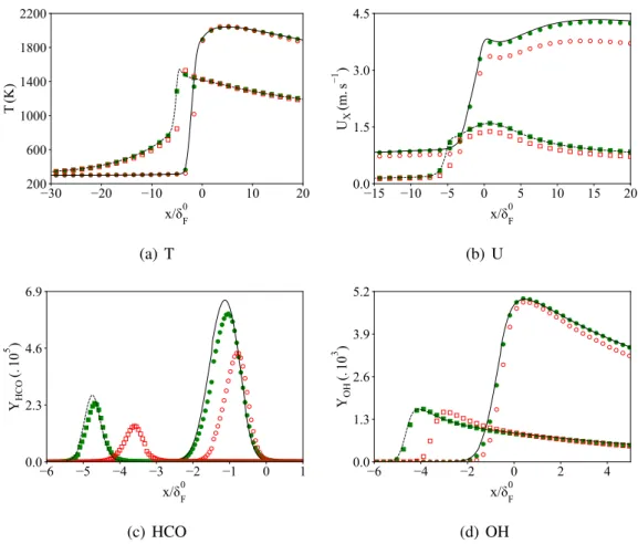
![Figure 3.2: Premixed flame with heat loss. Temperature and velocity. Detailed chemistry (GRI- (GRI-1.2 [41]): black lines](https://thumb-eu.123doks.com/thumbv2/123doknet/14675695.742374/76.892.125.778.550.816/figure-premixed-flame-temperature-velocity-detailed-chemistry-black.webp)
![Figure 3.3: Premixed flame with heat loss. Target species. Detailed chemistry (GRI-1.2 [41]):](https://thumb-eu.123doks.com/thumbv2/123doknet/14675695.742374/77.892.140.758.148.953/figure-premixed-flame-heat-target-species-detailed-chemistry.webp)
![Figure 3.4: Premixed flame with heat loss. Representative minor species. Detailed chemistry (GRI-1.2 [41]): lines](https://thumb-eu.123doks.com/thumbv2/123doknet/14675695.742374/79.892.120.777.260.833/figure-premixed-flame-representative-minor-species-detailed-chemistry.webp)