HAL Id: tel-01434160
https://hal.archives-ouvertes.fr/tel-01434160
Submitted on 13 Jan 2017HAL is a multi-disciplinary open access archive for the deposit and dissemination of sci-entific research documents, whether they are pub-lished or not. The documents may come from teaching and research institutions in France or abroad, or from public or private research centers.
L’archive ouverte pluridisciplinaire HAL, est destinée au dépôt et à la diffusion de documents scientifiques de niveau recherche, publiés ou non, émanant des établissements d’enseignement et de recherche français ou étrangers, des laboratoires publics ou privés.
Commande Robuste Structurée : Application Co-Design
Mécanique / Contrôle d’Attitude d’un Satellite Flexible
José Alvaro Perez Gonzalez
To cite this version:
José Alvaro Perez Gonzalez. Commande Robuste Structurée : Application Co-Design Mécanique / Contrôle d’Attitude d’un Satellite Flexible. Physique de l’espace [physics.space-ph]. INSTITUT SUPERIEUR DE L’AERONAUTIQUE ET DE L’ESPACE (ISAE), 2016. Français. �tel-01434160�
THÈSE
THÈSE
En vue de l’obtention du
DOCTORAT DE L’UNIVERSITÉ DE TOULOUSE
Délivré par : l’Institut Supérieur de l’Aéronautique et de l’Espace (ISAE)Présentée et soutenue le 14/11/2016 par : Jose Alvaro PEREZ GONZALEZ
Commande Robuste Structurée : Application Co-Design Mécanique / Contrôle d’Attitude d’un Satellite Flexible
JURY
Daniel ALAZARD Université de Toulouse/ISAE Directeur de thèse
Thomas LOQUEN ONERA Co-directeur de thèse
Christelle PITTET CNES Encadrante de thèse
Yann LE GORREC Institut FEMTO-ST Examinateur
Paolo GASBARRI Università Roma La Sapienza Rapporteur
Franck CAZAURANG Université de Bordeaux Rapporteur
École doctorale et spécialité :
EDSYS : Automatique 4200046
Unité de Recherche :
ONERA (DCSD)
Directeur(s) de Thèse :
Daniel ALAZARD, Thomas LOQUEN et Christelle PITTET
Rapporteurs :
Integrated Control/Structure Design of a Flexible Satellite
Using Structured Robust Control Synthesis
A PhD Dissertation
Submitted in partial fulfillment of the requirements for the degree of
DOCTOR OF PHILOSOPHY
(Automatic Control in Aerospace Engineering)
Authored by
Jose Alvaro PEREZ GONZALEZ
Supervised byDaniel Alazard
Thomas Loquen
Christelle Pittet
September 2016
Institut Superieur de l’Aeronautique et de l’Espace Ecole Doctorale Systemes
In dedication to my parents, Maria and Jose, for making me be who I am, and my girlfriend Silvia, for supporting me all the way. . .
Acknowledgments
First, I would like to express my sincere gratitude to my advisor Prof. Daniel Alazard for the continuous support of my Ph.D study and related research, for his patience, motivation, and immense knowledge. I would like to thank as well my co-advisors Thomas Loquen and Christelle Pittet for encouraging my research and for allowing me to grow as a research engineer. Your advice on both research as well as on my career have been priceless. Besides my advisors, I would like to thank the rest of my thesis committee: Prof. Paolo Gasbarri, Prof. Franck Cazaurang, and Dr. Le Gorrec, for accepting being members of my evaluation committee, for reviewing and evaluating the manuscript and for their insightful comments. I would like to thank as well Christelle Cumer, who has been very helpful at the beginning of the study and who has encouraged me during the whole thesis. I would like to thank the rest of the DCSD department of ONERA for making me feel at home, especially Mathieu Rognant, Charles Poussot and Cedric Seren for their help and support during these years.
Second, it is my pleasure to thank all my fellow labmates in ONERA for the stimulating coffee breaks and all the funny discussions we have had during lunch time and other non-official meetings. It is hardly difficult to make you understand how important you have been to me during all these years, and even more difficult to transmit this to the people who have already left ONERA or who do not have time to read this paragraph. Anyway, since this thesis will remain in the archives for ages, I hope one day you will do. Thanks to Emmanuel C., Jeremy L., Adrien M., Elodie D., Guillaume C., Patrick B. and Henry S. for integrating me in the group of PhD students during my first year, even though it was really difficult to understand my hard Spanish accent. Your attitude and understanding showed me the way for staying on my feet during this hard test. My second year has been marked by the meeting of Hélène E., with whom I have shared many unforgettable moments discussing about space, control/mechanics theory and ordinary-life problems, and by getting to know Mathieu B., Guillaume A. and Jorrit T., with whom I have shared many pleasant discussions. The third year has been even brighter than the previous ones thanks to the illuminating and generous smiles of Adèle B., Marine H. and Lylia S., who have transmitted me their happiness and optimism. I cannot forget my office colleague Martin S., with whom I have shared many great moments and interesting discussions about life and the career. And thanks as well to the new arrivals, Pauline K., Matteo G., Mehdi, Lucie and Vincent B., who have taught me
the knowledge of the street and with whom I wish I have spent more time... Thank you all, the past, the present and the future doctorants, you make the DCSD a really nice place to work.
Finally, I would not like to finish this part of the acknowledgements without thanking the rest of the research and education community at ONERA, CNES and ISAE-Supaero. Elyse R., thank you for helping me with my English and, the most important, for the many pleasant times I have had in your class discussing about space, philosophy and life in general. Your support and comprehension have been very valuable all these years. I would like to thank my other teacher, Sylvie S., who has helped me improve my French and with whom I have shared many interesting conversations about literature and history. Thanks a lot to Sofia U. as well, our far away coffee breaks have helped to decrease the stress of the thesis. To conclude, I want to thank all the invisible effort that many different Spanish and French professors have put on my education. None of this would have been possible without their altruistic help.
En esta segunda parte de los agradecimientos, quiero aprovechar mi mayor destreza con la lengua de Cervantes para agradecer, de corazón, a la gente que puede entenderme ya sea porque hablan español o porque lo entienden.
Durante estos tres largos años he tenido el privilegio de compartir casa y vivencias con varias personas que, inevitablemente, quedaran grabadas en mi memoria. Muchas gracias a Adrián C., que me ofreció mudarme a su casa y jugar con su consola a pesar de lo malo que era. Además, me enseñaste que si algo se quiere intensamente, con sacrificio y con un plan se puede conseguir. Mi querido Igor, aunque desaparecieras todos los días para ir a trabajar con tu tesis, que sepas que guardo muy buenos recuerdos de nuestras bromas y nuestros cantos con tu guitarra, lástima que tuvieras que ir a EEUU y dejar el apartamento. Y como no olvidarme de mi doblemente compañero de piso, Andrea S., con quien nunca he parado de aprender cosas, de reírme, de debatir amablemente y de cocinar. Has sido un ejemplo para mí en todo, desde la actitud hacia el trabajo hasta la forma de tratarse a uno mismo, y es por eso que todo lo que pueda escribir aquí para agradecértelo, es poco.
En ONERA tuve la suerte de compartir mis inquietudes en largos paseos al sol alrededor del edificio E con mi garant, vecino, co-worker, spotter, doer y amigo, el ahora Doctor Gustavo A., Dr Gus. Siendo los dos ingenieros con la misma visión de las cosas, con la misma escuela, con el mismo parcours, con el mismo humor e incluso con las mismas raíces, era obvio que acabaríamos entablando una gran amistad. Gracias a él hoy puedo (podemos) decir que he (hemos) acabado la tesis con un mínimo de dignidad y de cordura. Por no hablar de su crucial ayuda hacia el final, cuando tuve que compaginar Cannes con Toulouse. Raquel B. también tiene un gran mérito en este logro, puesto que incluso cogió un día de sus vacaciones para ayudarme el día de mi soutenance. Y además hace unas croquetas buenísimas. No me voy a cansar de agradecerles a Gus y Raquel lo mucho que me han ayudado y servido como apoyo a lo largo de la tesis, sobre todo los últimos meses en los que ya estaba solo contra el peligro. También en ONERA conocí a otra persona increíble, Lucia S., que desde el primer día me ilumino con su alegría y generosidad. Probablemente el primer año hubiera tirado la toalla si no fuera porque durante los seis meses que ella estuvo allí siempre me animó y alegró las
mañanas, y también los fines de semana con planes superguays y videos de youtube aún más
increíbles. Gracias de corazón. También gracias a su chico, Sergi L., que siempre ha estado
ahí para lo que hiciera falta y que no dudó en ningún momento en dejarme su casa para que pudiera estar tranquilo el día de mi soutenance. También gracias a Oleguer B., que aunque se fue al principio y me dejo solo ante el peligro, siempre nos ha seguido uniendo la amistad que forjamos aquí en Toulouse cuando todo era más difícil para los dos.
El tiempo no perdona a nadie, y estos tres años han estado marcados por la gente que ha tenido que irse de Toulouse y por la gente que he tenido la oportunidad de conocer. Gracias a los dobles diplomas, Maxi L., Joaquin G., Javier S., Jordi M. y Fernando G., que aunque os fuisteis yendo uno a uno y parecía como si poco a poco arrancasen nuestra foto de Toulouse, siempre hemos estado en contacto y viéndonos de vez en cuando sin que el paso del tiempo afectara nuestra amistad. También gracias al grupo thirsty monk, Iñigo T., Guiomar D., Juan I., Antonio F., Xavier G., Marine W. y Rubenes, con los que me lo he pasado muy bien y que han supuesto mi reavituallamiento de esta larga maratón. También un agradecimiento especial a Jesus J., mi mexicano favorito y que ha tenido siempre la virtud de saber aguantarnos a Andrea y a mí.
Y cuando hecho la vista atrás, no puedo olvidarme de mi gran amigo Pablo S. con el que he compartido de todo: profesores cizalladores de cerebros (martensita revenida), cursos infumables (mmm mathematica, docaer), cervezas, sentimientos (es guy love), películas (la pesca del salmon en yemen la mejor), piso (la maison de merabti), agua y gas (cortes en la maison de merabti), y, sobre todo, amistad. Tantas veces me has ayudado o iluminado que ya he perdido la cuenta... y lo minimo era ponértelo por escrito aquí y ahora. Y ya que estoy en Madrid, quisiera agradecer la pequeña contribución de mis amigos de toda la vida, Alberto P., Ruben M., Alejandro P., Maria, Laura A. y Sara, que siempre que volvía a Madrid estaban deseando verme sin yo merecerlo mucho.
Y ya no tengo palabras ni vocabulario ni expresiones suficientes para agradecerle a Silvia P. lo que ha hecho por mí, no ya solo por esta tesis, sino en mi vida. Cuando nadie miraba, cuando todo estaba oscuro y no parecía haber ni un atisbo de luz, ella siempre estaba ahí, cálida, comprehensiva y sonriente, para guiarme hacia la salida. Aun habiendo visto y vivido mi lado más oscuro, siempre ha decidido estar a mi lado ayudándome en mis proyectos. Por todo esto y mucho más, no puedo más que consolarme a solamente poder amarla hasta el último aliento esperando que algún día mi deuda se salde, algo que probablemente ocurrirá cuando los átomos que alguna vez formaron mi cuerpo se desintegren en el núcleo de una nueva estrella dentro de eones y eones.
Por último, quisiera agradecer a mi familia los esfuerzos que han hecho durante toda mi vida para ayudarme a estar hoy aquí. Mis padres, mi hermana, mis abuelos, mi tía y mi prima en la distancia siempre han estado apoyándome para que esto saliera adelante, haciendo de mi entorno un lugar estable para que pudiera crecer como profesional y como persona. Su sacrificio siempre ha sido y será un ejemplo para mí y para mi futuro.
Contents
Acronyms and Abbreviations xix
Nomenclature xxi
I Background 1
1 Introduction 3
1.1 Control of Flexible Space Structures: A Brief History . . . 3
1.2 Thesis Context . . . 8
1.3 Thesis Overview . . . 9
2 Literature Review 11
2.1 Studies on the Modeling of Large Flexible Structures . . . 12
2.2 Studies on Control of Large Flexible Structures . . . 18
2.3 Studies on Integrated Control/Structure Design . . . 21
3 Materials and Methods 25
3.1 Introduction to Mechanics . . . 26
3.2 Introduction to Robust Control Theory . . . 31
II Study 35
4 Setting the Modeling Framework of Flexible Multi-Body Structures in
Automatic Control 37
4.1 Selection of the Motion’s Kinematic Description . . . 39
4.2 The Double-Port Approach as an Overlapping Mechanism . . . 41
4.3 Substructure’s EOM Manipulation . . . 48
5 Modeling of Flexible Multibody Structures for Integrated Control/Struc-ture Design 57 5.1 One Connection Point . . . 58
5.2 Two Connection Points . . . 61
5.3 Extension to Revolute joint . . . 64
5.4 Extension to Piezoelectric Actuators . . . 66
5.5 Implementation of Parametric Variations . . . 71
5.6 TITOP Modeling of Flexible Multibody Systems . . . 74
6 Application and Validation of the TITOP Technique for the Modeling of Flexible Multibody Systems 77 6.1 Beam-like Substructures . . . 78
6.2 Planar Rotatory Flexible Spacecraft . . . 90
6.3 Two-Link Flexible Manipulator . . . 98
7 Control Strategies Evaluation for Control of Flexible Multibody Struc-tures 105 7.1 Control of Rigid Body Motion . . . 106
7.2 Control of Flexible Modes . . . 113
8 Implementation of Integrated Control/Structure Design in Structured H∞ Form 123 8.1 General Procedure and Scheme for Integrated Design. . . 124
8.2 Implementation of Specifications and Constraints . . . 126
8.3 Co-Design of a Rotatory Spacecraft . . . 134
9 Integrated Control/Structure Design of a Flexible Satellite 143 9.1 System Description. . . 144
9.2 System Modeling . . . 146
9.3 System Specifications . . . 148
9.4 Integrated Design Study . . . 151
III Conclusions 163 10 Discussion 165 10.1 Results in Flexible Multibody Systems Modeling . . . 165
10.2 Results in Integrated Design . . . 166
11 Conclusion 169 Résumé de Thèse en Français 173 12 Résumé en Français de la Thèse 173 12.1 Introduction, état de l’art et méthodes . . . 173
12.2 Cadre pour la Modélisation de Structures Flexibles Multi-Corps . . . 174
12.3 Modélisation de Systèmes Multi-Corps Flexibles pour le Co-Design . . 177
12.4 Application et Validation de la Technique TITOP aux FMS . . . 182
12.5 Evaluation des Stratégies de Contrôle pour les FMS . . . 183
12.6 Mise en œuvre du Co-Design sous Forme H∞structuré . . . 185
12.7 Co-Design Contrôle/Structure d’un Satellite Flexible . . . 188
APPENDIX 195
A Superelements 195
B Beam Finite Elements 199
C Thermal Induced Vibrations 203
D Code Matlab Functions 207
D.1 Conversion of ∆ block . . . 207
D.2 Derivation of the TITOP Model . . . 208
E Other Figures 217
E.1 Complementary Figures from Chapter 6 . . . 217
E.2 Complementary Figures from Chapter 7 . . . 220
List of Figures
1.1 First flexible spacecraft . . . 4
1.2 OGO III . . . 5
1.3 NuSTAR Illustration . . . 6
1.4 NuSTAR Thermal Distortion . . . 6
1.5 ASTRO-H Illustration . . . 7
1.6 ASTRO-H debris . . . 7
3.1 Direct dynamics block diagram . . . 29
3.2 Standard form representation . . . 32
3.3 Small-gain theorem diagram . . . 33
3.4 Multi-channel synthesis . . . 34
4.1 Substructure representation with two connection points . . . 39
4.2 Representation of the floating frame approach . . . 40
4.3 TITOP block diagram . . . 42
4.4 Flexible pointing system illustration . . . 43
4.5 Flexible pointing system decomposition . . . 44
4.6 Block diagram of Appendage 1 DP model . . . 46
4.7 DP assembly of the flexible pointing system . . . 47
4.8 Displacement decomposition in CMS . . . 49
5.1 Substructure representation with one connection point . . . 59
5.2 Substructure block diagram with one connection point . . . 60
5.3 Substructure representation with two connection points . . . 61
5.4 TITOP block diagram . . . 63
5.5 Substructure representation with revolute joint . . . 65
5.6 Substructure block Diagram with revolute joint . . . 66
5.7 Substructure representation with bonded piezoelectric material . . . 68
5.8 Actuated TITOP block diagram . . . 71
5.9 TITOP LFR Model . . . 73
5.10 Illustration of a FMS . . . 75
5.11 TITOP Modeling and assembly of a FMS . . . 76
6.1 Chain of flexible beams . . . 79
6.2 Concatenation of flexible beams. . . 79
6.3 Z-Dynamics of chainlike flexible beams illustration . . . 80
6.4 Bode response beam chain Z . . . 80
6.5 Y-dynamics of chain-like flexible beams illustration . . . 81
6.6 Bode response beam chain Y . . . 81
6.7 Piezoelectric beam element . . . 82
6.8 Beam with piezoelectric material frequency response, single voltage case . . . 84
6.9 Beam with piezoelectric material frequency response, multi voltage case . . . 85
6.10 Charge-Voltage transfer functions . . . 85
6.11 Transfer function for small variations . . . 86
6.12 Transfer function for large variations . . . 87
6.13 Transfer function small variations chain of beams . . . 88
6.14 Transfer function large variations chain of beams . . . 89
6.16 Rotatory spacecraft’s TITOP modeling . . . 92
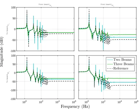
6.17 Bode TITOP vs AMM for nominal case . . . 95
6.18 Bode TITOP vs AMM for no tip mass case . . . 96
6.19 Bode TITOP vs AMM for heavy tip mass case . . . 97
6.20 Uncertain rotatory spacecraft representation. . . 97
6.21 Error comparison TITOP/AMM . . . 97
6.22 Bode plot of symmetric variations . . . 98
6.23 Bode plot of asymmetric variations . . . 99
6.24 Illustration of the planar two-link flexible arm . . . 100
6.25 Assembly of a two-link flexible arm . . . 101
6.26 Time response TITOP VS Nonlinear model of the two-link flexible arm . . . 102
7.1 Rigid synthesis of a PD controller. . . 107
7.2 Root locus of the flexible pointing system . . . 108
7.3 Nichols Diagram for the controlled system with real actuator dynamics (10 ms delay) . . . 109
7.4 Robust synthesis of the PD controller . . . 109
7.5 Nichols plots comparing robust synthesis with standard rigid approach . . . . 110
7.6 Nichols plots comparing standard rigid approach alone and with closed-loop active damping . . . 111
7.7 Nichols Plot comparing decentralized optimization to centralized optimization 112 7.8 Acceleration feedback applied to the flexible pointing system and to a flexible beam. . . 114
7.9 SOF applied to the flexible pointing system and to a flexible beam . . . 115
7.10 Integral Force Feedback applied to the flexible pointing system and to a flexible beam. . . 116
7.11 Other active damping strategies. . . 118
7.12 Root locus of the flexible pointing system with heavier appendage(m2= 1.2 kg)119 7.13 Pole zero flipping of a flexible system . . . 120
7.14 Recovering alternate pole zero of a flexible system . . . 120
7.15 Root locus considering real actuator dynamics. . . 121
8.1 Integrated design scheme . . . 126
8.2 ASF Template . . . 128
8.3 SOTAS synthesis scheme. . . 129
8.4 SOTAS synthesis scheme with integral effect. . . 129
8.5 SOTAS synthesis in a FMS TITOP assembly scheme . . . 130
8.6 SOTAS synthesis scheme with flexible motion specifications . . . 131
8.7 Slope comparison . . . 133
8.8 Bode ID vs Control Optimization Alone . . . 135
8.9 Dynamic specifications template and system response before optimization . . 137
8.10 Dynamic specifications template and system response after optimization . . . 139
8.11 Nichols Plot comparing the response of the ICSD and COA solutions . . . . 140
8.12 Time-domain Plot comparing the response of the ICSD and COA solutions . 140 9.1 Illustration of the Extra Long Mast Observatory (ELMO) . . . 145
9.2 Sketch of ELMO . . . 146
9.3 Mast prototype . . . 147
9.4 TITOP modeling of ELMO . . . 148
9.5 Template requirements and ELMO frequency response . . . 151
9.6 ASF Template and the obtained controlled system transfers . . . 153
9.7 Nichols Comparison with/without active damping strategies . . . 154
9.8 Nichols Comparison among active damping strategies. . . 155
9.9 Nichols plot comparison with/without rolloff . . . 156
9.10 Responses to disturbance impulse at the hub with VM and perfect dynamics 156
9.12 Instability of the PD alone strategy in the VM . . . 157
9.13 Hub position and thermal torque disturbance . . . 158
9.14 Nichols comparison for different actuator placement . . . 159
9.15 Performance comparison of different actuator placement . . . 160
9.16 System mode shapes for different configurations . . . 160
9.17 Optimized PEA configuration VS nominal PEA configuration . . . 161
A.1 Superelement Representation . . . 196
C.1 Thermal disturbance . . . 204
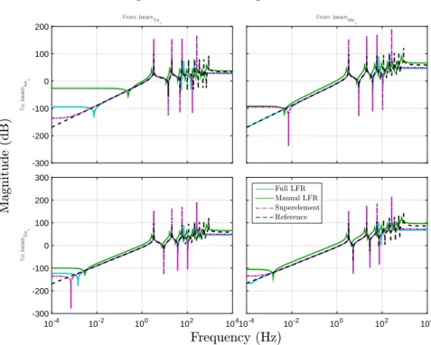
E.1 Transfer Functions at point P for small variations on the beam’s length . . . 217
E.2 Transfer Functions at point P for large variations on the beam’s length . . . 218
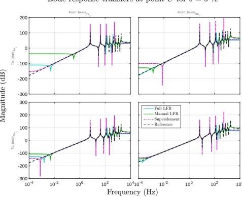
E.3 Transfer Functions at point C for small variations on the beam’s length inside the chain of beams . . . 218
E.4 Transfer Functions at point C for large variations on the beam’s length inside the chain of beams . . . 219
E.5 SOF controller applied to the flexible pointing system with heavy flexible ap-pendage (m2= 1.2 kg) . . . 220
E.6 SOF controller with complex zero applied to the flexible pointing system with heavy flexible appendage (m2= 1.2 kg) . . . 220
List of Tables
6.1 Table of beam and piezoelectric parameters . . . 82
6.2 Error analysis single beam parameterization for 100 samples . . . 87
6.3 Spacecraft configuration parameters . . . 91
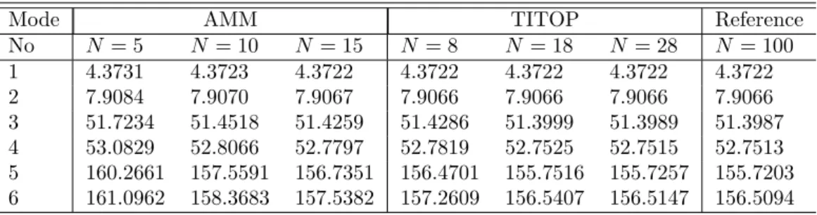
6.4 Frequency comparison rotatory spacecraft . . . 95
6.5 Arm configuration parameters . . . 100
6.6 Frequency comparison TITOP vs Nonlinear for the two-Link flexible arm . . 101
8.1 Rotatory spacecraft ICSD results . . . 138
9.1 ELMO configuration parameters . . . 146
9.2 Summary of the results of the ICSD of ELMO. . . 152
9.3 Fail/success summary of PEAs location x1 = 2m . . . 159
9.4 Fail/success summary of PEAs location x1 = 3m . . . 159
Acronyms and Abbreviations
ACS Attitude Control System
AF Acceleration Feedback
AMM Assumed Modes Method
AOCS Attitude and Orbit Control System
ASF Acceleration Sensitivity Function
CMS Component Modes Synthesis
COA Control Optimization Alone
CSI Control-Structure Interaction
DP Double-Port
DOF Degrees Of Freedom
ELMO Extra Long Mast Observatory
EOM Equation of Motion
FE Finite Element
FEM Finite Element Model
FM Flexible Mode
FMD Flexible Multibody Dynamics
FMS Flexible Multibody System
FE-TM Finite Element Transfer Matrix
GM Gain Margin
ICSD Integrated Control/Structure Design
IFF Integral Force Feedback
LFT Linear Fractional Transformation
LFR Linear Fractional Representation
LMI Linear Matrix Inequality
LQR Linear Quadratic Regulator
LTI Linear Time Invariant
PCO Plant-Controller Optimization
PD Proportional-Derivative
PEA Piezo-Electric Actuator
PID Proportional-Integral-Derivative
PPF Positive Position Feedback
PM Phase Margin
RM Rigid Mode
RW Reaction Wheel
SOF Second Order Filter
SOTAS Second Order Template on Acceleration Sensitivity
TITOP Two-Input Two-Output Port
TMM Transfer Matrix Method
Nomenclature
Generalized displacements in equations and figures are expressed as follows: {q} column matrix of generalized displacements.
{ ˙q} column matrix of generalized velocities. {¨q} column matrix of generalized accelerations.
The vector {q} of generalized displacements is often decomposed as follows (identically for generalized velocities and generalized accelerations):
{x} generalized translations. {θ} generalized rotations.
Generalized coordinates can be projected in the following directions or frames:
~
x unit vector along x axis.
~
y unit vector along y axis.
~z unit vector along z axis.
Subscripta Reference frame or vector associated to body a.
SubscriptRi inertial reference frame or reference frame associated to i-th body when speci-fied.
SubscriptRG reference frame at point G.
The equations of motion and figures may include the following elements: [K] square matrix of system generalized stiffness.
[D] square matrix of system generalized damping coefficients. [M ] square matrix of system generalized masses.
{F } column matrix of generalized loads. [ ¯φR] matrix of rigid-body modes.
[ ¯φC ] matrix of constraint modes. [ ¯φN ] matrix of natural modes.
{Fc} vector of externally applied forces at the constraint degrees of freedom.
{ ˜Fe} vector of loads acting on a substructure as a result of its connection to adjacent
sub-structure at the constraint degrees of freedom.
{Fr} vector of externally applied forces at the rigid-body degrees of freedom.
{ ˜Fr} vector of loads acting on a substructure rigid body degrees of freedom as a result of
its connection to adjacent substructure.
where the vectors of loads are usually decomposed in the following sub-vectors: {FP} Applied point force at point P .
{TP} Applied torque at point P .
{η} column matrix of normalized displacements.
Nr or subscriptr dimension of rigid body modes.
Ne or subscripte dimension of redundant constraint modes.
Nn or subscriptn dimension of fixed-constraint modes.
N dimension of total degrees of freedom.
[τP G] kinematic model between points P and G.
[DAG] Inverse dynamics rigid-body model of a structure A at point G. (∗P G) Skew-symmetric matrix associated to the vector {P G}.
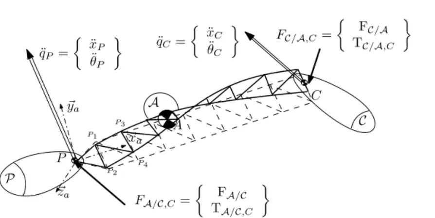
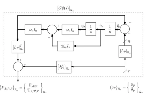
The TITOP model uses the following notations:
{FA/P,P} vector of loads exerted by a substructure A to a substructure P at point P . {fA/P,P} force exerted by a substructure A to a substructure P at point P .
{tA/P,P} torque exerted by a substructure A to a substructure P at point P . [GAP(s)] one-connection-point TITOP model of substructure A at point P .
[GAP,C(s)] two-connection-point TITOP model of substructure A at points P and C. [JPA] rigid body matrix or direct dynamic model of substructure A at point P . [LP] modal participation matrix of natural modes at point P .
[HP,CA (s)] two-connection-point TITOP model of substructure A at points P and C with a revolute joint at point P .
Other mathematical notations are:
In Identity matrix of size n × n.
Part I
Background
Chapter
1
Introduction
“Start by doing what’s necessary; then do what’s possible; and suddenly you are doing the impossible.” - Francis of Assisi
T
he objective of this PhD thesis is to perform integrated attitude control/structure design of a large flexible satellite using structured H∞ synthesis, by modeling flexible multibody structures anddeveloping a control strategy for the controller’s synthesis of flexible multibody systems. This chapter introduces in Sec. 1.1the problematic of the control of flexible structures to the reader, and explains in Sec. 1.2in which way this problem has been addressed in the field of attitude control. Finally, Sec.
1.3 states the main guidelines of the thesis.
1.1
Control of Flexible Space Structures: A Brief History
Since the beginning of the space era, spacecraft have been sent into space to satisfy a wide variety of technological challenges, scientific researches, commercial requirements and defense necessities. His-torically, spacecraft attitude control has been considered as the primary objective to be achieved by the spacecraft control system. Spacecraft dynamics are controlled to strict requirements which depend on the pointing budget, spacecraft function mode, orbit environment and onboard sensors and actuators. During the last decades, space science has been looking for new ways of discovering and analyzing celestial objects in the Universe to understand some aspects of Einstein’s theory of relativity, such as gravitational waves or the origin of the Big Bang. Analysis of the Universe’s most violent events is needed in order to improve our current understanding of physics. The most violent events in the Universe are related to black holes, black holes collisions, supernovas remmants or galaxy clusters, among others. The study of these high-energy celestial objects requires X-ray and Γ-ray instruments which can only work outside Earth’s atmosphere. These instruments require long focal lengths to improve image quality, which can vary from 4 m to more than 20 m long.
There are two ways of fulfilling the requirement of long focal lengths: satellite formation flying and distributed instrumentation. In satellite formation flying the focal distance is equal to the distance between the two satellites, each one containing different parts of the instrumentation, but this require a high-precision attitude control, which considerably increases the spacecraft’s costs. The distributed
4 Chapter 1. Introduction
(a) Sketch of Explorer I (Source: NASA) (b) Illustration of Alouette I (Source: CSA)
Figure 1.1: First experiences with flexible interaction in space
instrumentation approach uses different deployable parts of the spacecraft to increase the focal length of the instruments, such as extensible benches or deployable booms. This solution is less expensive and more robust since only one satellite is needed and attitude control performances are not prohibitive. In addition, the relatively gentle environment of space, with no air-friction and no self-weight loads, allows the design and construction of spacecraft with complex geometries and large dimensions. As a result, distributed instrumentation is often the final solution.
Added to the requirement of long extendable parts, satellites need more and more power supply for the correct functioning of the onboard systems. This is translated into an augmentation of the solar panel’s surface, making the satellite larger. Moreover, antennas are becoming larger as well since larger size increase its sensibility for detecting radio waves. As a result, spacecraft structure is discretized in “modules” or substructures which allow a simplification of system’s modeling, analysis, production, assembly and integration. Nowadays, a spacecraft is a Flexible Multibody System (FMS) composed of a platform or rigid hub, to which several substructures are attached such as antennas, deployable booms, solar arrays or extendable masts. The mass increase, however, is minimized since satellites’ weight is limited to a few tones due to launching rocket maximum take-off weight. Hence, there is a structural tendency of enlarging spacecraft’s dimensions and lightening its structure, which makes the spacecraft large and flexible.
Elastic behavior of spacecraft structure is a well known problem since the beginnings of the space race. Flexible interaction with the control of spacecraft dynamics can occur in numerous and subtle ways, worsening the spacecraft dynamics or structure’s flexible deformations. The control system designer must be aware of it and consider flexibility in his synthesis models. Although engineers have always been aware of these interactions, some of them may go undetected and may even provoke spacecraft’s loss. The first records about flexible interactions go back to the Explorer I and Alouette I, the first artificial satellites of USA and Canada, respectively.
Explorer I (1958) was an Earth-orbiting spacecraft with a long cylindrical body with four flexible antennas extending laterally (see Fig. 1.1a). The vehicle was to be passively spin stabilized about its principal axis of minimum moment of inertia. However, after one orbit it started experiencing precessional motion and after a week the vehicle was stabilized rotating about its axis of maximum moment inertia, which was not suspected before the flight. Rotation about either the maximum or minim moment of inertia is stable for a rigid body, so engineers started searching which mechanism provoked that change in the rotation axis. The answer was that Explorer I was not rigid because of the whip antennas. The antennas have an associated bending motion coupled with the precessional motion, provoking an energy dissipation process until the minimum-energy state (rotation about the
1.1. Control of Flexible Space Structures: A Brief History 5
(a) Artist concept of OGO-III (Source: NASA)
(b) Sketch of OGO-III (Source: NASA)
Figure 1.2: OGO-III was the first active controlled satellite experiencing boom-bending difficul-ties
maximum moment of inertia) was achieved [Tutt 69]. Since then, the destabilizing effects of structural energy dissipation in spin-stabilized spacecraft are counterbalanced by an active nutation damper system.
Flexibility can also interact with the environment, as experienced by Alouette I (1962). This vehicle had a compact central body and four antennas, two of them 22.9 meters long and the other two 11.4 meters long (see Fig. 1.1b). The antennas were extendable booms which were deployed after launch. The spacecraft was spin stabilized about its axis of maximum moment of inertia, but since its launch a rate of spin decay was detected. After three years the satellite stopped spinning. Research revealed that the spin brake mechanism was caused by the interaction of the flexible boom with solar and radiation pressure. The solar radiation provoked the asymmetrical bending of the booms by thermal distortion which, with the interaction of the solar pressure, induced a net torque to the body
[Tutt 69]. The torque might either help or oppose the spin depending on the vehicle’s geometry, but
in the case of Alouette I the spin rate was opposed. The following missions solved this problem by adding small metallic reflectors at the ends of the booms, which provided a compensating torque.
When three-axis active attitude control started being implemented, control engineers continued encountering flexible interaction problems. Due to the large dimension and low mass density of some satellites, flexible modes are in the low-frequency band and they may interfere with the attitude control system’s bandwidth. Therefore, the control system has to be modified due to nonnegligible structural flexibility, otherwise the action of the spacecraft control system may worsen the structural deformations as well as the spacecraft dynamics. Despite engineers’ awareness, some satellites have experienced control-system/structure interaction which caused the failure of their mission.
The first Control-Structure Interaction (CSI) problem was experienced by the OGO-III (Orbiting Geophysical Observatory, 1966) satellite. This vehicle, depicted in Fig. 1.2, had two 6.10-meter boom parallel to the pitch axis and one 9.14-meter boom parallel to the roll axis. In addition, two solar arrays were mounted along the roll axis. It had an active feedback system to control roll attitude, using reaction wheels and gas jets to unload momentum saturation. Ground control noticed that when the satellite approached perigee, roll-axis oscillations of 0.42 Hz were detected, increased in amplitude until the reaction wheels, gas jets and solar-array drive were all excited. However, reaction-wheel and solar-array oscillations were sustained until the vehicle approached apogee of its orbit. Control-system/boom-flexibility was suspected as the cause of the oscillations. Analysis showed that there was a discrepancy in the amount of structural damping assumed in the preflight closed-loop stability analysis. Sustained oscillation of 0.42 Hz could be possible if boom damping ratios of 0.3 % were used, and not the preflight values of 1 % and 2 % [Tutt 69]. The next missions used a different delay logic
6 Chapter 1. Introduction
Figure 1.3: Artist concept of the NuSTAR mission
Figure 1.4: Thermal distortion of NuSTAR’s optical axis (Source: NuSTAR Observatory Guide)
for the reaction wheel control and improved the dynamic model for synthesis.
Yet, many lessons can be drawn from these examples and these lessons retain their value today. Understanding of CSI problems has helped to significantly improve satellite’s reliability and life limit. Indeed, there are very few records about CSI problems during the 80s and the 90s, even if modern spacecraft is more complex. An example of the improved know-how is the NuSTAR mission (Nuclear Spectroscopic Telescope Array, 2012), the first focusing high energy X-ray space observatory. NuSTAR employs grazing incidence optics to be able to focus X-rays. For this, a 10.15-meter focal length Wolter telescope is held at the end of a long deployable mast. A laser metrology system is used to determine the exact relative positions of the optics and the focal plane at all times. The spacecraft attitude control system is designed to actively control the attitude to within 1 arcsec during an observation, performing adjustments to keep the spacecraft z axis oriented towards the science target. For that, the control system has been conceived to reject disturbances in a maximized bandwidth subject to maintain gain and phase stability margins in the range of 6-8 dB and 30-45 degrees [Ruth 10]. The mission is achieving all its scientific objectives, even though the induced vibrations due to the thermal flexing of the mast (see Fig. 1.4).
Despite the recent technological advances in control/structure design, even nowadays the attitude control system can fail and provoke spacecraft loss. This is the case of the Hitomi satellite
(ASTRO-H, 2016). ASTRO-H (Fig. 1.5) was conceived to reveal the structure and evolution of the universe
1.1. Control of Flexible Space Structures: A Brief History 7
Figure 1.5: Artist concept of the Hitomi (ASTRO-H) satellite (Source: JAXA)
Figure 1.6: ASTRO-H debris spinning at 5.2 revolutions per second as seen by the Subaru Telescope (Source: National Astronomical Observatory of Japan)
octagonal platform containing all the basic sensors and actuators (star trackers, reaction wheels, etc), two solar array pads attached and an extensible optical bench up to 12 meters long. One month after launch, on March 26th 2016, the unexpected behavior of the attitude control system caused incorrect determination of its attitude as rotating, although the satellite was not rotating actually. In the result, the reaction wheel was activated and lead to the rotation of satellite. In addition, the magnetic torque believed to avoid the reaction wheel’s saturation did not work properly. Judging the situation as critical, the safe hold mode switched on automatically, using the thrusters to stop the rotation. However, the attitude control system provided an atypical command and the spacecraft’s rotation was indeed accelerated. Once the satellite’s speed exceeded the design values, the most vulnerable parts of the spacecraft (solar arrays, the deployable mast) separated off from the satellite, as it was observed by the Subaru Telescope (see Fig. 1.6). The causes of the attitude control system anomaly are still being inquired, but the lost of all communication with the satellite have made this task almost impossible.
The history of flexible satellite control has demonstrated to be plenty of challenges and techno-logical advances. The larger and lighter modular spacecrafts often imply a rigorous study of the CSI problem in order to minimize the probability of failure. Although a significant improvement has been made since the launch of the first flexible satellites, robust and reliable attitude control systems are needed in order to accomplish successfully future scientific missions. Approaches which simultane-ously take into account the structural behavior and the control system actions are an added value when dealing with the CSI problem.
8 Chapter 1. Introduction
1.2
Thesis Context
In the field of attitude control of large flexible satellites, the main objective is to guarantee system stability against low-frequency perturbations and induced vibrations. Nevertheless, new generation satellites must accommodate high-precision scientific experiments and reduce launching costs, what is making the design of their structure larger and lighter. More precisely, new generation space science experiments need X-ray interferometer benches and long-range telescopes with long focal lengths, both needing long masts clamped to the spacecraft platform. Furthermore, large flexible satellites are now discretized or modularized in several substructures in order to recycle its design for other satellite platforms. The large size and lightness imply low-frequency flexible modes that may interfere with the controller’s bandwidth, destabilize the system and eventually provoke its loss, in what is called the Control Structure Interaction (CSI) problem. On the other hand, system modularity implies a lack of knowledge to predict the dynamic behavior of the entire assembled system and, consequently, impedes working directly in pre-design phases of the control/structure system.
In the space sector, this problem is solved with a loop of crossed-information between the control and the structure departments, who have to establish the minimal specifications for each system in order to achieve a successful integration. These specifications include determining a minimum value for frequency of the first flexible mode, fixing a maximal mass for the whole system, a maximal size for several substructures, etc. For these specifications, performance barriers are imposed for each system, ensuring a successful final integration. Nevertheless, these barriers do not allow exploiting the maximum optimal capacities of the two systems working together.
That is the reason why new conception methods, which tie together spacecraft structural dynamics
and attitude control laws design, were born. Messac and Malek [Messac 92] designed the structure
and the control system of a rotatory flexible spacecraft, addressing system’s disturbance rejection and system’s command following performance, while optimizing the profile of the flexible appendage for minimum mass. The model used was a FE-model of a simplified flexible spacecraft, controlled by a hub-torque commanded with a full-order controller. Both the structure and the controller were optimized with an algorithm developed by the authors. Messac and Malek thereby demonstrated that control/structure optimization gives better results than control optimization alone in terms of mass costs and control performances. However interesting, their approach had limitations when dealing with real design scenarios and robustness. The authors modeled the whole system without taking account the advantages of modularity, and the controller optimization did not use robust synthesis techniques. Alazard et al. [Alazard 13b] performed integrated attitude control/structure design of an Earth Obervation satellite using a genetic algorithm for the system’s optimization. The modeling technique allowed modular system assembly by interconnecting the different parts of the system such as the hub and flexible appendages. The models were FE-based, in LFR representation for the optimization of structural parameters. The attitude control system consisted of a low-order controller for each stabilization axis and a roll-off filter. This study supposed the first step to a generic approach to integrated control/structure design since it provided tools for flexible multibody system modeling and an approach for attitude control. However, the proposed modeling technique did not allow the interconnection of different substructures among them. In addition, the optimization process was iterative and several software were involved: NASTRAN for re-computing the FE-models, the genetic algorithm and the µ synthesis. This made the co-design study complex and time-consuming.
Taking advantage of the structured H∞ form, Alazard [Alazard 13a] used a multi-model H∞
synthesis scheme to design a fixed-structure controller of an earth-observation satellite. Simultaneously, avionic parameters (sensors and actuators delay) were optimized in order to select the ideal actuator
1.3. Thesis Overview 9
for challenging requirements or standard requirements. This supposed the first study in integrated
control/avionics design using structured H∞ tools. The study demonstrated that the same level
of performance could be achieved with less expensive actuators and sensors when optimizing the
control/avionic system simultaneously. Nevertheless, the modeling technique was the same as in
[Alazard 13b] and thus the interconnection among flexible substructures was not possible.
Thanks to the aforementioned studies, integrated attitude control/structure design is feasible and useful. Feasibility is the result of the studies using the most modern algorithms for structure/control
optimization, such as genetic algorithms or non-smooth H∞ optimization. Usefulness since these
studies demonstrate that there is always additional benefits when considering the control system and the structure simultaneously for control law and structural design. However, no study provided
a modeling technique which takes into account the modularity of flexible multibody systems. In
addition, no study has performed integrated control/structure design of flexible multibody systems using structured H∞tools.
1.3
Thesis Overview
The objective of this research is to perform integrated attitude control/structure design of a large flex-ible satellite using structured H∞synthesis, by modeling flexible multibody structures and developing
a control strategy for the controller’s synthesis of flexible multibody systems. This study involves a multidisciplinary research in which the modeling of mechanical systems, control law synthesis and con-trol law validation must be integrated. Furthermore, the approach must be able to isolate and manage the parameters to be optimized, either mechanical parameters or control law parameters. Therefore, the thesis approach starts dealing with the modeling techniques of large flexible structures, the mod-eling of actuators and sensors for control of flexible structures and the implementation of parametric variation in those models. The thesis continues with the evaluation of the different control strategies which can be used using the models provided in this study, to conclude with the implementation of the integrated/control design scheme in structured H∞ form and the application of this scheme to a
flexible satellite.
Chapters 1, 2 and 3 recall the background of this study. Chapter 2 explains and situates the
different studies carried on modeling, control and integrated design of flexible structures. Chapter3
recalls briefly some concepts of general mechanics, structural mechanics and control theory which are used in this study.
Chapter4is entirely devoted to setting the framework for the modeling of FMS. The objective is to propose a general theoretical framework for the modeling of FMS using finite element (FE) data and use it for integrated control/structure design. The foundations of the framework are developed according to the needed kinematic description, the needed overlapping mechanism and the required form of equation of motion. This chapter has motivated the publication of [Alazard 15].
Chapter5 uses the framework stated in Chap. 4 to develop the theory for the modeling of FMS
for use in automatic control. The chapter provides straightforward mechanical models for modeling starlike or chainlike flexible structures, piezoelectric substructures and revolute joints. Parameteri-zation possibilities are also evaluated. A part of the results of this chapter have been published in
the ASME Journal of Dynamic Systems, Measurement and Control [Perez 16b] and in several
inter-national conferences: EURO GNC 2015 [Perez 15a], IFAC ACNAAV 2015[Perez 15b] and IFAC ACA
10 Chapter 1. Introduction
Chapter 6 provides a set of applications of the developed modeling technique for FMS stated
in Chap. 5. The modeling method is explained and validated in representative examples of FMS
modeling. A comparison of the proposed modeling technique with the Assumed Modes Method (AMM) is provided and its advantages are highlighted. These examples can also be found in the produced publications [Perez 16b], [Perez 15a], [Perez 15b] and [Perez 16a].
Chapter 7 evaluates the different control strategies that can be applied for the attitude
con-trol/vibration suppression of flexible multibody structures. Collocated/non-collocated damping and centralized/decentralized synthesis schemes are compared and discussed. The control strategies are
explained through an academic example and applied for the developed models of Chaps. 5 and 6 in
order to chose the most adequate control architecture for the integrated control/structure design. Chapter8is devoted to explain how to implement the integrated control/structure design problem in structured H∞form. The general framework is explained and guidelines for imposing the rigid-body
motion and the flexible motion specifications are given. Other utilities, as minimization of command energy and roll-off specification, are illustrated. The implementation is illustrated with the co-design of an academic model of a flexible spacecraft.
Chapter9uses the knowledge developed in the precedent chapters to perform the integrated atti-tude control/structure design of a flexible satellite. The flexible satellite is modeled with the proposed flexible multibody system technique, performing integrated design according to mission specifications. Part of the results have been published in the international conference IFAC ACA 2016 [Perez 16c].
The last part, consisting of Chaps. 10 and 11, is dedicated to discuss and resume the main
contributions of the PhD, and to provide the guidelines that may help other future studies in the domain. The manuscript is supplemented by a set of appendixes which provide further notions in finite elements, more figures and the Matlab code of the most used functions during the study.
Chapter
2
Literature Review
“Be sure you put your feet in the right place, then stand firm.” - Abraham Lincoln
Contents
2.1 Studies on the Modeling of Large Flexible Structures . . . . 12
2.1.1 General Framework . . . 12
2.1.2 FMD using floating rotating frame . . . 13
2.1.3 FMD using corotational rotating frame and inertial frame. . . 16
2.1.4 Actuator/Sensor Models for Flexible Structures Control . . . 17
2.2 Studies on Control of Large Flexible Structures . . . . 18
2.2.1 Attitude Control of Large Flexible Structures. . . 19
2.2.2 Vibrations Suppression of Large Flexible Structures . . . 19
2.3 Studies on Integrated Control/Structure Design . . . . 21
Integrated Control/Structure Design is a vast domain which comprehends two major engineering fields: modeling and control of flexible structures. This chapter aims to explain the different modeling approaches which can be used and the main applications in control of flexible structures. The chapter reviews and merges these two different domains with the discussion of what has been accomplished so far in the integrated design domain.
12 Chapter 2. Literature Review
I
n this chapter, the state-of-the-art of the problematic associated with integrated con-trol/structure design is summarized. Integrated concon-trol/structure design comprehends two clearly distinguished areas: modeling and control. First, the existing modeling tech-niques that deal with large flexible structures are explained. In addition, the modeling of the actuators and sensors used to control these kind of systems is addressed. Second, studies on control of large flexible structures are presented, focusing on attitude control and vibra-tion suppression applicavibra-tions. Finally, a review of the integrated structure/control design is explained.2.1
Studies on the Modeling of Large Flexible Structures
Modeling of large flexible structures has been a major concern in control applications for the last thirty years due to the development of larger and lighter structures [Wasfy 03]. Large size and reduced mass imply lower natural frequencies which are typically closely spaced [Schoen 09]. Low natural frequencies may interfere with controller’s bandwidth, affecting the whole dynamical behavior of the system. Simple and accurate models for large flexible structures which predict these characteristics are indispensable for designing, optimizing and controlling engineering systems. In Sec. 2.1.1, the method for dealing with the modeling of large flexible structures and a widely used classification of modeling techniques are established. Next, Secs. 2.1.2and 2.1.3 present the most representative studies of the different modeling types. In Sec. 2.1.4, a short review of the different existing models of actuator and sensors for flexible structure control is presented.
2.1.1 General Framework
The study of large flexible structures implies dealing with large dynamics models. This is mainly attributed to the high amount of degrees of freedom (DOF) which have to be considered for an accurate modeling of the structure, making their analysis complex and time-consuming. In order to reduce the complexity and facilitate structural understanding, the so-called substructuring techniques are used, consisting of the macrodiscretization of the large system into a set of subsystems known as substructures, appendages or modules, which in turn are separately modeled. This strategy considers then the large flexible structures as a Flexible Multibody System (FMS) or Flexible Multibody Structure (FMS); i.e, a group of interconnected rigid and deformable components, each of which undergoing translational and rotational motions [Wasfy 03].
In order to analyze the dynamic response of FMS due to external conditions, it is necessary to compute the Flexible Multibody Dynamics (FMD). FMD has a significant importance for the design, optimization and control of many practical systems such as space vehicles [Masoudi 11,
Guy 14] or robot manipulators [Chatlat. 09, Boscariol 10]. In design, FMD can be used to calculate the system parameters such as dimensions, configuration, and materials that minimize the system cost while satisfying the design safety constraints such as strength,
2.1. Studies on the Modeling of Large Flexible Structures 13
rigidity, and static/dynamic stability. FMD is used in control applications for predicting the response of the multibody system to a given control action and for calculating the changes in control actions necessary to direct the system towards the desired response.
However, obtaining the FMD of a FMS is not a simple task. It is the result of a long and tedious process. First, it is mandatory to chose the kinematic description of the motion of the different elastic bodies experiencing small or large displacements. This kinematic description can be done in three different ways according to the chosen reference frame: using either a
floating frame, a corotational frame or an inertial frame. Second, the semi-discrete equations
governing the elastic and rigid motion of each substructure are derived, depending on the particular nature of each component: beam models are used for 1D components, plate and shell models for 2D members and continuum models for 3D components. The equations can be obtained either analytically, semi-analytically or using any kind of discretization method, like the finite element (FE) discretization. Third, the constraints between the different sub-structures are established as constraint equations. These constraints can be in the form of prescribed motion (one or several DOF are forced to follow a given motion), joints (several DOF are related) or contact/impact (one or several DOF are constrained to a value within a given interval). To conclude, implicit or explicit solution assembly procedures are used to solve the semi-discrete equations of motion along with the constraint equations, obtaining the desired FMD.
As it has been shown, getting the FMD is the result of the multiple possible choices to derive the model. In this review the publications on FMD are mainly divided according to the kinematic description of the motion (floating frame, corotational frame or inertial frame) since they are directly related to the different type of applications. Other categories can be done according to the different steps along the FMD computation, but they are not revised here. The reader might head to [Shabana 97] or [Wasfy 03] if a more detailed review of modeling of multibody systems is desired.
2.1.2 FMD using floating rotating frame
The floating frame is currently the most widely used method in the simulation of FMD. Developed in the early 1970s, the floating frame is an intermediate reference frame which is attached to a flexible component and follows the average local rigid body motion. The total displacement is evaluated by superimposing small elastic deformations on the large rigid body motion. This simplifies the calculation of the internal forces, leading to rapid computation of the FMD. It is the most efficient method for the simulation of FMS undergoing small elastic deformations and slow rotational speeds such as satellites and space structures, a domain in which it has been systematically applied. In [Kane 80], Kane and Levinson made use of the floating frame to derive the FMD of a complex spacecraft with seven different kinematic formulations (momentum principle, Lagrange’s equations, D’Alambert Principle or Hamilton Canonical Equations, among others) and then in [Kane 81] they added the elastic displacements considering constrained and unconstrained beam elements in order to analyze and simulate large displacements. In [Likins 69], Likins also made use of the floating frame
14 Chapter 2. Literature Review
to derive the kinematic description of flexible space vehicles. Since then, Kane’s and Likin’s formulations have been applied in many studies. For example, in [Masoudi 11] Masoudi and Mahzoon applied the Kane’s approach in order to derive a model of a free-floating space robot with four linkages and to perform maneuvering and vibration control.
The main advantage of the floating frame approach resides on its usage to extend modal analysis and experimental modal identification techniques to FMS. This is performed by iden-tifying the mode shapes and frequencies of each flexible component. Then, the first n modes (where n is determined by the required accuracy and the nature of the problem) are super-posed on the rigid body motion of the component represented by the motion of the floating frame. This is what is called the Assumed Modes Method (AMM). In [Likins 67], Likins was one of the first authors which used the modal analysis within a floating reference frame in order to derive the equations of motion of a free rotating spacecraft. In [Hughes 74], Hugues superimposed the natural modes and constrained modes of the different flexible appendages to the rigid motion of a space vehicle in order to study the implications of the flexibility on the attitude dynamics, and obtained the so-called impedance matrix of the spacecraft, a tool to analyze the influence of spacecraft flexibility. In [Pascal 88], Pascal extended the work of [Hughes 74] by performing the dynamic analysis of a system of hinge-connected flex-ible bodies, obtaining the reduced dynamic impedance matrix of a generic tree-structure. In [Turner 80], Turner and Junkins also used the AMM in addition to a kinematic description obtained with the Hamilton’s Principle in order to compute the optimal single-axis reorien-tations of a flexible vehicle.
Furthermore, the effect of inertial forces, as the centrifugal stiffness, can be taken into ac-count in this approach in a non-linear way, because accelerations are measured with respect to a rotating frame (the floating frame attached to the appendage). In [Likins 73] this is per-formed for a spinning flexible spacecraft, and showed the influence of centrifugal stiffness on the flexible appendage modes shapes and natural frequencies. Besides flexible space vehicles modeling, other uses of the floating frame approach include modeling of flexible robot manip-ulators [Chatlat. 09,Boscariol 10,Usoro 86] and rotorcraft modeling [Zhu 97,Choura 91].
However, in the majority of FMD literature on floating frame approach, the flexible com-ponents are discretized using the FE method. FE-based models are the most powerfull tool for structural analysis [Usoro 86,Rong 11,Bokhari 08]. This has lead to develop direct substruc-turing techniques based on the FE method, taking for granted the use of a floating frame to superpose rigid and elastic displacement, and with constraint equations established through boundary conditions to the FE models. Among these techniques, two methods have drawn researchers’ attention for decades: the Finite Element Transfer Matrix (FE-TM) method and the Component Modes Synthesis (CMS) Method. It should be noticed that in the litera-ture, these techniques are not directly mentioned as floating-frame-based techniques, they are conceived as independent techniques for substructuring large FE models.
2.1. Studies on the Modeling of Large Flexible Structures 15
2.1.2.1 Component Modal Synthesis Techniques
The CMS method has received significant attention in the aerospace industry since its idea of matrix condensation lends itself particularly well to the concept of substructuring. It is an extension of modal analysis that is particularly applicable to large flexible systems [Ersal 08]. First, it uses modal analysis to obtain a proper model of each subsystem. Then it assembles these subsystem models conforming the whole structure, taking into account the different frames for the different substructures. Among the available dynamic substructuring methods, CMS stands the most systematic and efficient procedure for developing a satisfactory decomposed model [Dhingra 94,Craig Jr 00,Ersal 08].
CMS techniques are divided in three main categories, depending on the selection of com-ponent modes for the substructure’s assembly. There is a wide choice of comcom-ponent modes [Craig Jr 00]: normal modes (which can be fixed-interface normal modes, free-interface normal modes and loaded-interface normal modes) constraint modes, rigid-body modes, attachment modes, residual flexibility modes and residual flexibility attachment modes. The reader might head to [Craig Jr 00] if more information about component modes is required. The three main categories are:
• Methods based on constraint and fixed-interface normal modes. These approaches use a combination of constraint modes (which include rigid-body modes) and fixed-interface
normal modes for substructure coupling. The most known methods are the Hurty’s
method [Hurty 65] and the Craig-Bampton’s method [Craig 68]. The Imbert’s method (also called effective-mass method, [Imbert 79,Alazard 08]) is included in this category as well. The main aspects of these methods will be discussed and compared in Chap.
4.
• Methods based on ressidual flexibility and free-interface normal modes. More difficult to implement, especially when a substructure has rigid-body freedom. Hintz [Hintz 75] and Macneal [MacNeal 71] have developed methods which fall into this category. • Methods based on loaded-interface normal modes. Mainly used for acquisition of the
substructure’s data for FE model verification.
CMS techniques have been a widely used for modeling and assembling flexible substruc-tures. Several research articles have studied how to obtain representations of substructures modeled with FE. In [Young 90], Young substructured the complete FE model of a two-dimensional truss in order to synthesize a distributed control law. Nevertheless, here the substructure assembly process was mainly based on the overlapping between the inertia and stiffness matrices provided by the substructures’ FE model. This required deep knowledge of the FE theory and impeded straightforward concatenation of complex structures. Shortly after, Sunar [Sunar 92] started studying FE models substructuing at a more general level applying Guyan static condensation, a specific type of CMS. Later, Su [Su 95] proposed a CMS-based method to decompose a structure into a collection of substructures to synthe-size decentralized controllers, and called it Substructural Controller Synthesis. However, the
16 Chapter 2. Literature Review
overlapping between systems was done at the matrix level, presenting the same practical disadvantages as in [Young 90].
The aforementioned studies did not compute the substructure’s state-space representation and did not develop a more intuitive overlapping method. Guy [Guy 14], based on Alazard [Alazard 08] and Cumer [Cumer 01], came up with a state-space representation from the sub-structure’s FE model in order to represent the linear dynamics of a spacecraft with flexible appendages in star-like structure. Imbert’s method was used in order to transfer the influence of flexible appendages to the spacecraft main hub. However, it did not allow for the repre-senting of flexible substructures in chain-like assembly and the results were not compared with other methods.
2.1.2.2 Finite Element Transfer Matrix Method
The FE-TM method has not enjoyed the same degree of application as the CMS method, but it has been proved a powerful tool for the analysis of structures. Leckie [Leckie 60] stated the fundamentals of the transfer matrix method, which can be seen as a continuity function for a flexible system with transferable boundaries among the substructures. Later, Dokainish [Dokainish 72] merged the FE method with the transfer matrix method for the dynamic analysis of plates and presented it as the FE-TM method. Since then, many researchers extended the technique and used it for many different applications. MacDaniel [McDaniel 77] applied the method for orthogonally stiffened structures and demonstrated the efficiency of the FE-TM by computing the frequency response of a two row-five span plate structure. Sankar [Sankar 80] used the method to show fast convergence for obtaining natural frequencies of a cantilevered plate. Ohga [Ohga 83] extended and applied the method for the dynamic analysis of space frame structures, demonstrating the accuracy and efficiency of the method with numerical examples compared to classic FE substructure assembly. Rong [Rong 11] modified the FE-TM Method and its algorithms to solve the eigenvalue problem simply and conveniently, validating it on a plane wing model.
Other authors, like Yousuff [Yousuff 86] and Tan [Tan 90], modified the FE-TM method in order to create suitable models for flexible structures control. This method continues being improved by the works of authors such as Rui [Rui 08], who partially uses FE-TM to compute FMD of FMS, and enriched with other control applications as in Krauss [Krauss 10], where a non-collocated feedback is applied using the transfer matrix method.
2.1.3 FMD using corotational rotating frame and inertial frame
The corotational frame follows an average rigid body motion of an individual finite element within the flexible component. In this approach, the motion of a finite element is divided into a rigid body motion and natural deformation modes. The approach is used for static modeling of structures undergoing large displacements and small deformations. Some non-linear effects such as centrifugal stiffness are naturally included, and it has no limits on the magnitude


![Figure 3.1: Block diagram of the direct dynamic model of a satellite composed of a hub H and an appendage A ( F P T P ) = [D AP ] + [D P H ] ( x¨ Pθ¨P ) = [D AP ] + [τ GPT ][D G H ][τ GP ] ( x¨ Pθ¨P ) (3.17) It is more practical to express the whole dy](https://thumb-eu.123doks.com/thumbv2/123doknet/14612144.732562/58.892.241.665.154.366/figure-diagram-dynamic-satellite-composed-appendage-practical-express.webp)