(M, p, k)-Friendly Points: A Table-based Method to Evaluate Trigonometric Function
6
0
0
Texte intégral
Figure
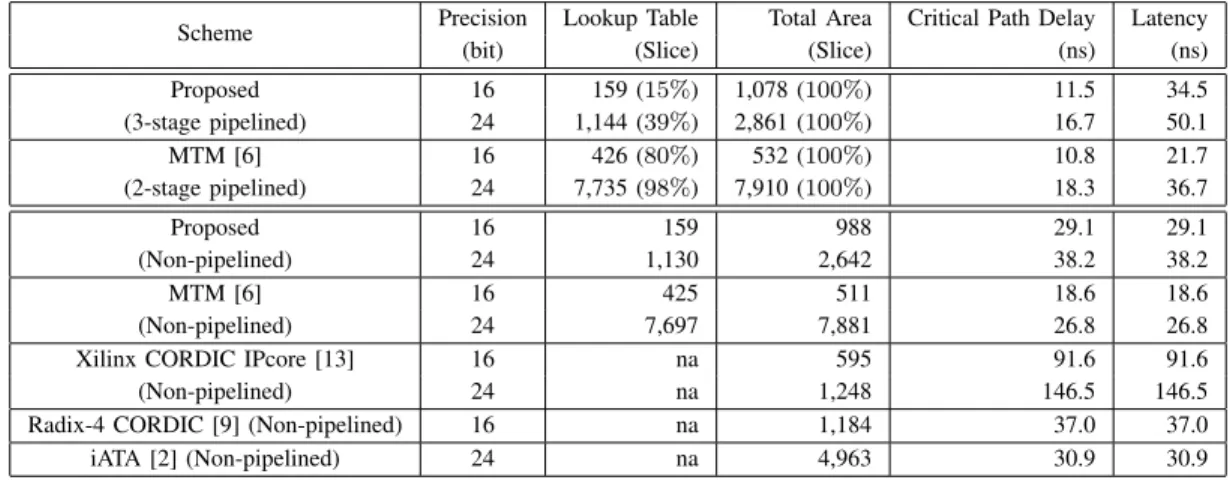
![Table III first compares the estimated hardware costs of the proposed design with three different schemes, namely, the multipartite table (MTM [6]), piecewise table lookup approxi-mation (Sasao [7]) and order-two interpolation (Lee [8])](https://thumb-eu.123doks.com/thumbv2/123doknet/14644901.735860/5.918.84.443.86.242/compares-estimated-hardware-proposed-different-multipartite-piecewise-interpolation.webp)
Documents relatifs