An Advanced Fast Steering Mirror for Optical
Communication
by
Daniel Joseph Kluk
B.S., Mechanical Engineering
Northwestern University, 2002
Submitted to the Department of Mechanical Engineering
in partial fulfillment of the requirements for the degree of
Master of Science in Mechanical Engineering
at the
MASSACHUSETTS INSTITUTE OF TECHNOLOGY
June 2007
c
Massachusetts Institute of Technology 2007. All rights reserved.
Author . . . .
Department of Mechanical EngineeringMay 24, 2007
Certified by . . . .
David L. Trumper Professor of Mechanical Engineering Thesis SupervisorAccepted by . . . .
Lallit Anand Chairman, Departmental Committee on Graduate StudentsThis work was sponsored by the Unted States Air Force under Air Force Contract
FA8721-05-C-002. Opinions, interpretations, conclusions and recommendations are those of the author and are not necessarily endorsed by the United States Government.
An Advanced Fast Steering Mirror for Optical
Communication
by
Daniel Joseph Kluk
Submitted to the Department of Mechanical Engineering on May 24, 2007, in partial fulfillment of the
requirements for the degree of
Master of Science in Mechanical Engineering
Abstract
I describe in this thesis the design, fabrication, assembly, and testing of an Advanced Fast Steering Mirror (AFSM) for precision optical platforms. The AFSM consists of a mirror driven in two rotational axes by normal force electromagnetic actuators, and controlled via position feedback loops. The dynamic performance is sufficient to provide high bandwidth (approximately 5 kHz) disturbance rejection of base motion, and as such the device is particularly suited to beam stabilization tasks in laser communication, lidar, and similar optical applications. In fact, work on the Mars Laser Communication Demonstration project at MIT Lincoln Laboratory provided the original impetus for developing the subject technology.
My work on this project is divided into five distinct phases: Electromagnetic and mechanical design of the mirror itself; fabrication and assembly of the mechanical hardware; initial testing and dynamic model generation; design and fabrication of an electronic analog controller; and final closed loop performance demonstrations. I performed the first two phases on the MIT campus, and the final three phases at MIT Lincoln Laboratory. Each project phase is described in detail herein.
Ultimately, I demonstrate performance from the hardware and control electronics exceeding the original design goal of 5 kHz. As this original prototype is merely a testbed, I also describe possible evolutions of the design to optimize form factor, performance, and flightworthiness.
I wish to thank the Advanced Concepts Committee at MIT Lincoln Laboratory for providing the sponsorship that made this project a success.
Thesis Supervisor: David L. Trumper Title: Professor of Mechanical Engineering
Acknowledgments
So many people have contributed to this small accomplishment that I will have great difficulty naming them all in this limited space. But rest assured, this work is not mine alone–not by a long shot. I owe many a debt of gratitude to all those mentioned here, who each in their own way have given me the knowledge, strength, discipline, love, and support I needed to see this task through to the very end.
First, I would like to thank my advisor, Professor David Trumper. Professor Trumper has been a source of vast knowledge and support from the very beginning of this project. Besides providing advice and insight into the design of the AFSM, he constantly motivated me to step outside of my comfort zone by challenging my ideas and expanding the scope of the project to fit my potential–despite the fact that I often didn’t know what the limit of my potential was! I owe many thanks to Professor Trumper for his teaching, wisdom, practicality, and encouragement.
In addition to Professor Trumper, five other individuals provided direct assistance, in various roles, on this project. Mike Boulet was very helpful in a wide variety of areas during the testing of the AFSM–especially, but not limited to, design and layout of the wire-wrap two-channel controller board and coding of several helpful Matlab scripts. Mike’s impeccable attention to detail and wizardry with Matlab were just what I needed during this time–especially given my relative weakness in both these areas.
Jamie Burnside was my primary contact at Lincoln Labs, and was instrumental in facilitating the initial proposal activity to secure ACC funding. He also set up design reviews, and provided much of the background information needed to set the AFSM performance goals. He also guided me through several key administrative tasks at Lincoln, such as purchasing.
Third is David Cuff, my labmate1 during the design phase of the AFSM. David
was instrumental as a sounding board for ideas, and we struggled through the finer points of magnetic analysis and control systems together. David also provided key insights into the design of the elastomer bearings. He has become a good friend.
The fourth key contributor is a man I haven’t even met in person: Fred Sommer-halter. Fred has worked with Professor Trumper for many years, and is an expert craftsman who performs coil winding and other magnetic assembly work as a hobby. Fred performed the critical work of winding the AFSM coils and assembling the ac-tuator halves with the level of precision demanded by the design. Fred’s artisanship is self-evident in the hardware he builds, and the work he produced for the AFSM was no exception.
Finally, I owe thanks to Gerry Wentworth, the machinist in charge of the LMP machine shop. Gerry helped me in every aspect of the AFSM component fabrication, from the simplest turned parts to the most complex CNC-machined housings and base pieces. Besides being an excellent teacher of the machinist’s trade, Gerry is also very easy-going and friendly, and I enjoyed chatting and sharing stories with him.
Of course, I must also thank many others, whose contributions to this project
were less direct, but yet were equally essential to its success. First, I must thank my friends and colleagues at MIT, who in one way or another provided insight, tutoring, advice, camaraderie, and commiseration. Many thanks to the members of the PMC Lab: Emre Armagan, Joe Cattell, Larry Hawe, Aaron Gawlik, Dean Ljubicic, Ian MacKenzie, Kevin Miu, and our wonderful administrative assistant, Laura Zaganjori. I would also like to thank the officers and members of the Snowriders ski club, and my teammates on my various intramural sports teams–especially the GAME and Neanderthals hockey teams for allowing me to subject them to my pitiful goals-against average in net.
Second, thanks goes to several employees at Lincoln Labs for their assistance dur-ing my time there: Ed Corbett, Annmarie Gorton, Karen Sacco in the electronic stockroom, and Jeanne Clarke in Group 76 electronics. Special thanks go to Todd Mower for his help on the elastomer bearing stiffness investigation, and to Al Pills-bury for his explanations of the Lincoln HBSM hardware, and input into the AFSM mechanical design.
Next I’d like to acknowledge my friends, both in Boston and around the country, who in their own unique styles kept me laughing, loving, relaxed, and (relatively) stress-free while I ran the mental gauntlet that is MIT: Andrea Brand, Dariusz Golda, Cathy and Daniel Hsu, Jeremy Indick, Dave Ison, Paul King, Chad Laurent, Charlie McGinnis, Alex Mettler, RaNaye Neudauer, Kevin Paul, Kurt Schoonover, Matt St. Martin, Dave and Samantha Stagney, Melissa Stenach, Tami Urman, Bill Vogt, Ruthie Wertheimer, Ryan Wiechens, Justin Verdirame, and many others. I treasure your friendship and hope to spend more time visiting you now that this task is complete!
Finally, and most importantly, I wish to thank my family for all their love and support, not only at MIT, but in all other times of my life: My father Robert, my mother Carolyn, brothers Brian and Rob, and sisters Erin, Leanne, and Andrea. Rob, Erin, and Andrea passed away in a tragic auto accident in 2002. Since that time, my pursuit of success has been motivated by a desire to honor their memory, and capture a few of the opportunities that they were not able to realize during their short lives. To them I dedicate this work.
To Andrea, Erin, and Rob
Contents
1 Introduction 23
1.1 Thesis Organization and Summary . . . 23
1.2 Optical Communication Technology . . . 28
1.3 Motivations for AFSM Development . . . 29
1.4 Discussion of Prior Art . . . 33
1.4.1 Early Fast Steering Mirrors . . . 33
1.4.2 Recent Fast Steering Mirror Development . . . 34
1.5 AFSM Performance Goals and Design Constraints . . . 39
1.5.1 Limitations of Existing Technologies . . . 39
1.5.2 Enabling Technologies . . . 41
1.6 Final Performance Goals . . . 42
1.7 AFSM Operational Concepts . . . 43
2 Mechanical Design 49 2.1 Control System Considerations . . . 49
2.2 Mechanical Design Goals . . . 53
2.3 Sizing for Desired Mechanical Performance . . . 55
2.3.1 Mirror and Armatures . . . 55
2.4 Flexure Design . . . 60
2.4.1 Axial Flexure . . . 61
2.4.2 Elastomeric Bearings . . . 64
2.5 Modal Analysis of the Dynamic Structure . . . 75
3 Electromagnetic Actuator Design 87
3.1 Fundamentals of Electromagnetism . . . 87
3.1.1 Electrical Circuit Analysis . . . 88
3.1.2 Magnetic Circuit Analysis . . . 92
3.1.3 Basic Magnetic Circuit Equations . . . 93
3.2 AFSM Magnetic Design . . . 102
3.2.1 Magnetic Circuit Analysis . . . 104
3.2.2 Material and Geometry Selection . . . 111
4 AFSM Assembly and Electrical Integration 121 4.1 Mechanical Fabrication and Assembly . . . 121
4.1.1 Machined Parts and Subassemblies . . . 123
4.1.2 Actuator Coil and Core Assembly . . . 130
4.1.3 AFSM Final Assembly . . . 135
4.2 Power Electronics and Sensors . . . 141
4.2.1 Power Amplifier Selection . . . 141
4.2.2 Power Amplifier Current Compensators and Signal Inverter . . 143
4.2.3 Capacitance Probes . . . 149
4.2.4 Capacitance Probe Rotation Electronics . . . 150
4.2.5 Optical Sensors and Electronics . . . 154
5 System Identification, Controller Design, and Experimental Results 159 5.1 System Design Using Capacitance Probe Feedback . . . 160
5.1.1 Open-Loop Dynamics . . . 160
5.1.2 Analog Compensator . . . 168
5.1.3 Closed-Loop Performance Using Capacitance Probe Feedback 173 5.2 System Design Using Optical Feedback . . . 177
5.2.1 Open-Loop Dynamics . . . 178
5.2.2 Analog Compensator . . . 181
5.2.3 Closed-Loop Performance Using Optical Feedback . . . 186
5.3.1 Integrated Electronics Board . . . 193
5.3.2 Axis Coupling Measurement . . . 193
5.3.3 Dual Axis Operation . . . 197
5.4 Performance Summary . . . 201
6 Conclusions and Suggestions for Future Work 203 6.1 Optimization for Acceleration and Small-Signal Bandwidth . . . 203
6.2 Optimization for Power Consumption, Mass and Form Factor . . . . 207
6.3 Optimization for Optical Flexibility . . . 210
6.3.1 Reflective Mirrors . . . 210
6.3.2 Refractive Lenses . . . 210
6.4 Conclusions . . . 211
A AFSM Magnetic Analysis Via Maxwell’s Equations 213 B AFSM Stiffness Investigation 221 B.1 Stiffness Verification . . . 221
B.2 Hypotheses for Stiffness Anomaly . . . 224
B.3 Testing of Hypotheses . . . 225
B.3.1 Improper Design . . . 225
B.3.2 Over-Constraint of Elastomer . . . 226
B.3.3 Elastomer Compression Effects . . . 227
B.3.4 Elastomer Material Properties . . . 229
B.4 Investigation Conclusions . . . 235
C Analog Compensator Analysis 237 C.1 Lag Network . . . 237
List of Figures
1-1 Finished AFSM base assembly, prior to electrical integration. . . 24 1-2 CAD model view of the AFSM moving mechanical components. . . . 25 1-3 The AFSM flux-steering actuator. . . 25 1-4 Azimuth closed-loop frequency response using the optical quad cell. . 27 1-5 Elevation closed-loop frequency response under optical feedback. . . . 27 1-6 Simplified Mars Lasercomm spacecraft optical component schematic
(from Hawe [11]). . . 30 1-7 Spacecraft pointing error PSD plots for various active and passive
iso-lation cases. Plot courtesy of Jamie Burnside. . . 32 1-8 Cambridge Technology model 6400, a single-axis galvanometer. . . 34 1-9 A fast-steering mirror which employs voice-coil actuation, built by Ball
Aerospace Corporation. . . 35 1-10 Two-axis reaction-free scanning mirror developed by Ball Aerospace
(image from Patent No. 6,612,192). . . 36 1-11 Cutaway view of the Lincoln Laboratory High Bandwidth Steering
Mirror (HBSM). . . 37 1-12 Isometric CAD rendering of the AFSM showing the actuators arrayed
around the central mirror. The dashed lines indicate the rotation axes of the mirror. . . 44 1-13 Cross-sectional view of the AFSM showing the mirror, flexure supports,
capacitance probes, and actuators. . . 46 1-14 Cross-sectional view of the magnetic actuator showing component detail. 47
2-1 Example of an AC-coupled system . . . 51
2-2 A mathematically tractable, but physically impossible control scheme for the AC-coupled system . . . 52
2-3 Idealized Open-Loop Plant Frequency Response . . . 54
2-4 CAD rendering of the AFSM moving mirror and armature design, along with its flexure supports. . . 56
2-5 Elastic modulus E plotted against density ρ (from /citeashby). . . 58
2-6 Fabricated AFSM mirror and armature assembly. . . 60
2-7 AFSM fabricated axial flexure . . . 64
2-8 Comparison of elastomeric and metallic flexure form factors. . . 68
2-9 Chart used to determine effective compression modulus Ec given elas-tomer hardness and shape factor. Reprinted from Lindley [14]. . . 72
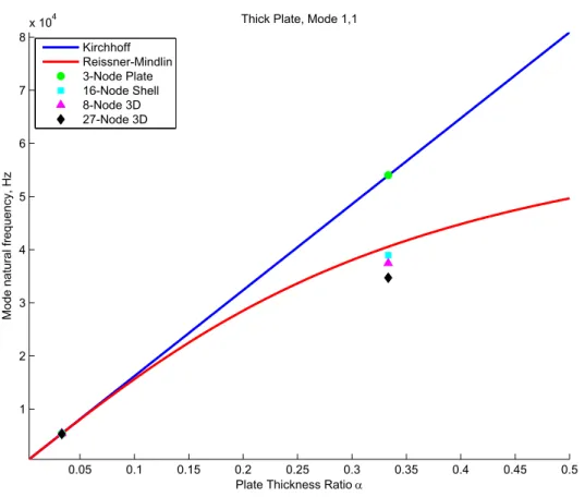
2-10 Mode (1,1) Analytical solutions and finite element results for thin (α = 0.03) and thick (α = 0.33) cases. The black diamond is considered to be the “exact” solution. . . 77
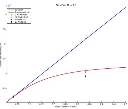
2-11 Expanded view of the results in Figure 2-10: Thin (left); thick (right) 77 2-12 Mode (2,2) Analytical solutions and finite element results for thin (α = 0.03) and thick (α = 0.33) cases. The black diamond is considered to be the “exact” solution. . . 78
2-13 Expanded view of the results in Figure 2-12: Thin (left); thick (right) 78 2-14 AFSM mirror structural mesh with free boundary conditions. . . 81
2-15 FSM first structural mode shape, free boundary conditions . . . 83
2-16 FSM second structural mode shape . . . 83
2-17 FSM third structural mode shape . . . 84
2-18 FSM fourth and fifth structural mode shapes (the fifth mode is sym-metric with the fourth mode depicted here) . . . 84
2-19 FSM sixth structural mode shape . . . 85
3-1 A jet-pipe servovalve cross-section showing the electromagnetic torque motor. . . 88
3-2 Electrical and magnetic circuit analogues with identical energy storage properties. Note that qin and qL represent charges, not currents. . . . 96
3-3 Norton equivalent circuit of a linear permanent magnet source. . . 99 3-4 Th´evenin equivalent circuit of a linear permanent magnet source. . . 99 3-5 Cross-sectional view of the magnetic actuator showing component detail.103 3-6 Flux-steering actuator principle of operation. . . 103 3-7 Magnetic circuit representation of the flux-steering actuator. . . 105 3-8 Early design iteration showing low-profile core for increased optical
access to the mirror. . . 116 4-1 Gerry Wentworth and the Bridgeport Torq-Cut TC3 CNC mill, on
which many of the AFSM parts were machined. . . 122 4-2 Fabricated ASFM actuator housings prior to core and coil installation. 123 4-3 The fabricated AFSM base plate. . . 124 4-4 The AFSM backiron assemblies prior to final grinding. . . 125 4-5 The mirror and armature assembly during epoxy bonding of the
arma-tures to the mirror. Note the fine wires used to establish the optimal bond thickness. . . 127 4-6 Illustration showing the axial flexure assembly technique. The lower
armature airgap sets the mirror position, and the flexure is adjusted axially to accommodate it. . . 128 4-7 The capacitance probes installed in the alignment fixture during
bond-ing of the probe housbond-ings (threaded brass parts over the probes). . . . 130 4-8 Probe clamp with probes and axial flexure installed. . . 131 4-9 Stainless steel mandrel and forming tools used to wind the AFSM coils,
shown with a coil installed. Photo courtesy of Fred Sommerhalter. . . 133 4-10 A finished coil assembly after forming and bonding. Photo courtesy of
Fred Sommerhalter. . . 134 4-11 An assembled actuator half filled with potting compound. Photo
4-12 The potted actuator halves installed on a fixture plate ready for grind-ing. Photo courtesy of Fred Sommerhalter. . . 136 4-13 Finished actuator halves after final grind. . . 136 4-14 The complete set of fabricated AFSM components, prior to final
as-sembly. . . 137 4-15 The probe sensor clamp installed in the base plate using an alignment
pin (brass part in the center). Note the access holes in the base plate for the clamp screws at the bottom of the figure. . . 137 4-16 Thin shims in place over the lower actuator core poles in preparation
for mirror assembly. The lower actuator halves are temporarily bolted to the AFSM base. . . 138 4-17 The mirror assembly clamped in place with a fixture plate prior to
bonding of the axial flexure. . . 139 4-18 The magnet assemblies bonded to the elastomeric bearings and
arma-tures. . . 139 4-19 The finished AFSM base assembly. . . 140 4-20 The base assembly installed on its angle plate. . . 140 4-21 Rear view of the AFSM assembly showing the installed capacitance
probes. . . 141 4-22 Model 7541 (top) and 7560 (bottom) power amplifiers mounted in their
racks during AFSM testing. Note also the shield terminations on the four cables at the output terminal block at middle-right. . . 144 4-23 Power portion of the control loop showing the power amplifier and
sense resistor in series with the AFSM actuator (modeled as a resistor in series with an inductor). . . 145 4-24 Frequency response of the AFSM actuator and series sense resistor. . 146 4-25 Current compensator circuit for the power amplifiers (one circuit per
amplifier). . . 147 4-26 Closed-loop current response showing resonant peak at 40 kHz. . . 148 4-27 Command signal inversion circuit (one circuit per actuator pair). . . . 149
4-28 The set of four capacitance probes prior to installation in the AFSM. 151 4-29 Capacitance probe conditioning electronics. . . 151 4-30 Capacitance probe labels and mirror coordinate definitions. . . 152 4-31 Probe displacements for θAZ and θEL mirror rotations. . . 153
4-32 Input stage of the capacitance probe rotation electronics (signal buffer-ing and subtraction). . . 155 4-33 Output stage of the capacitance probe rotation electronics (final
sub-traction and scaling). . . 156 4-34 The hardware used for collecting optical feedback measurements for
the AFSM. . . 156 4-35 The quad cell detector rotation and scaling electronics. . . 157 4-36 Block diagram of the AFSM system components. . . 158
5-1 The AFSM electronic support and test hardware at Lincoln Labora-tory. The HP 3562A DSA is on the left. . . 160 5-2 The AFSM installed on the optical table during testing, along with
optical test hardware. . . 161 5-3 Initial frequency response of elevation axis. . . 162 5-4 Frequency response of the capacitance probe and conditioner, courtesy
of Roy Mallory. . . 164 5-5 Frequency response of the AFSM actuator halves when configured as
a transformer (ratio of upper coil input voltage to lower coil output voltage). . . 165 5-6 AFSM elevation axis frequency responses at various current amplitudes
using capacitance probe feedback (ratio of capacitance probe voltage out to amplifier current command in). . . 166 5-7 AFSM azimuth axis frequency responses at various current amplitudes
using capacitance probe feedback (ratio of capacitance probe voltage out to amplifier current command in). . . 166
5-8 AFSM elevation axis frequency response used to design the controller for capacitance probe feedback (ratio of rotated capacitance probe volt-age out to amplifier current command in). . . 167 5-9 Capacitance probe controller design (green) with measured plant
dy-namics (blue) and resulting loop transmission (red). . . 168 5-10 The AFSM compensator circuit for use with capacitance probe
feed-back (one circuit per axis). . . 170 5-11 Analog capacitance probe compensator measured dynamics overlaid
with design values. . . 171 5-12 Measured loop transmission of the AFSM plus capacitance probe
ana-log controller. . . 172 5-13 Elevation closed-loop frequency response using capacitance probe
feed-back. . . 174 5-14 Azimuth closed-loop frequency response using capacitance probe
feed-back. . . 174 5-15 Elevation closed-loop frequency response with reduced loop gain. . . . 175 5-16 Azimuth closed-loop frequency response with reduced loop gain. . . . 175 5-17 Step response of the elevation axis under capacitance probe feedback. 176 5-18 The plastic enclosure used to protect the test setup from room air
currents. . . 177 5-19 AFSM elevation axis frequency response using optical (quad cell)
feed-back. . . 179 5-20 AFSM azimuth axis frequency response using optical (quad cell)
feed-back. . . 179 5-21 Comparison of frequency responses obtained using the optical quad cell
versus the capacitance probes. . . 180 5-22 Optical controller design (green) with measured plant dynamics (blue)
and resulting loop transmission (red). . . 181 5-23 The AFSM compensator circuit for use with optical feedback (one
5-24 Analog optical compensator measured dynamics overlaid with design values. . . 184 5-25 Measured AFSM loop transmission plot with optical compensator. . . 184 5-26 Second optical controller design (green) with measured plant dynamics
(blue) and resulting loop transmission (red). . . 185 5-27 Second optical compensator measured dynamics overlaid with design
values. . . 186 5-28 Elevation closed-loop frequency response using optical feedback,
show-ing 10 kHz bandwidth. . . 187 5-29 Azimuth closed-loop frequency response using optical feedback. The
loop went unstable during the test at 1.3 kHz. . . 189 5-30 Azimuth closed-loop frequency response with reduced gain. . . 189 5-31 Elevation closed-loop frequency response using the new optical
con-troller, showing flatter magnitude but retaining 10 kHz bandwidth. . 190 5-32 800-millivolt (20 µrad) step response using optical feedback and
con-troller. . . 191 5-33 5-volt (125 µrad) step response using optical feedback and controller. 192 5-34 Layout diagram of the wire-wrap connections on the underside of the
integrated electronics board. . . 194 5-35 Dual-channel wire-wrap integrated electronics board for two-axis testing.195 5-36 Elevation cross-axis plot showing coupling dynamics while driving
az-imuth. . . 196 5-37 Azimuth cross-axis plot showing coupling dynamics while driving
ele-vation. . . 196 5-38 Circular trajectory drawn at 2 kHz under dual-axis operation. . . 197 5-39 Lincoln Laboratory logo lissajous figure drawn at 500 Hz under
dual-axis operation. . . 198 5-40 Azimuth loop transmission measurement taken just prior to hardware
5-41 One of the failed azimuth axis armatures, shown with actuator half,
elastomer bearing and permanent magnet. . . 200
A-1 AFSM actuator with integration contours and surfaces for the analysis using Maxwell’s equations. . . 215
B-1 AFSM frequency response for determining rubber stiffness character-istics. . . 222
B-2 Elevation axis frequency response following failure of the azimuth axis, with azimuth actuators removed. . . 226
B-3 Backlit photograph of one of the azimuth actuators after failure, show-ing clearance around the elastomer bearshow-ing (arrows). . . 227
B-4 Finite element analysis results of elastomer bearing showing shear and compressive / tensile reaction forces. . . 228
B-5 Measured storage and loss modulus of 1mm thick Shore 70A neoprene sample in shear. . . 230
B-6 Comparison of storage modulus results between two sample sizes of 1mm thick Shore 70A neoprene in shear. The red line denotes a +1.7 dB slope. . . 230
B-7 Measured phase angle of various elastomer samples in shear. . . 231
B-8 Compression test of AFSM neoprene sample. . . 232
B-9 Measuring neoprene dynamic shear modulus using Augusto Barton’s test fixture. . . 233
B-10 Close-up of the shear test fixture. . . 234
B-11 Measured frequency response of AFSM neoprene in shear. . . 235
C-1 A general lag analog circuit network. . . 238
List of Tables
1.1 AFSM Measured Performance Characteristics . . . 26
1.2 HBSM-B Prototype Measured Performance . . . 38
1.3 AFSM Proposal Performance Goals . . . 39
1.4 AFSM Prototype Performance Goals . . . 43
2.1 17-4 PH Material Properties (Condition H900) . . . 63
2.2 Axial Flexure Design Values . . . 65
2.3 Elastomer Flexure Design Values . . . 74
2.4 Consolidated Mirror Stiffness and Natural Frequency . . . 74
2.5 FSM Structural Mesh Convergence Results . . . 82
2.6 FSM Modal Natural Frequencies, Final Mesh . . . 85
3.1 Armature Design Characteristics . . . 113
3.2 Actuator Magnetic Core Design Characteristics . . . 116
3.3 Coil Design Characteristics . . . 118
3.4 Actuator Force Output Characteristics . . . 119
4.1 Techron 7541 Power Amplifier Characteristics . . . 143
4.2 Techron 7560 Power Amplifier Characteristics . . . 143
4.3 ADE 2805 Capacitance Probe Characteristics . . . 150
5.1 AFSM Measured Performance Characteristics . . . 201
B.1 Bearing Hand Calculations vs. Finite Element Results . . . 228 B.2 AFSM Neoprene Static Mechanical Properties Measured Using the DMA232
B.3 AFSM Neoprene Static Mechanical Properties Measured Using the MIT Tester . . . 234
Chapter 1
Introduction
In this thesis I document the design and development of a novel mechanism for beam pointing and stabilization in optical systems: The Advanced Fast Steering Mirror (AFSM). My work on the device is part of a technology pathfinder for advanced optical communications systems research, led primarily by NASA and the United States Air Force. This work was sponsored by the Advanced Concepts Committee of MIT Lincoln Laboratory.
1.1
Thesis Organization and Summary
I open in Chapter 1 with a summary of my work and results, as well as an overview of the optical communication technology that provides the impetus for my research. I also review prior work in fast steering mirror technology, and how shortcomings in existing hardware have motivated the pursuit of the higher performance AFSM design. I conclude the chapter by stating the performance goals for the design, and provide an overview of the hardware configuration and operational principles. A photograph of the AFSM hardware is shown in Figure 1-1.
Chapter 2 covers the fundamental mechanical issues in the AFSM design. I first discuss the implications of the mechanical design on the control system design, and illustrate how fundamental choices made at this stage become critical for maximizing performance of the controlled system. After establishing mechanical dynamic goals,
Figure 1-1: Finished AFSM base assembly, prior to electrical integration.
I discuss the tradeoffs required to meet them. In particular, I consider the moving mirror mass versus stiffness properties, the selection of inertia and suspension stiffness values to properly prescribe the mirror’s rigid body resonant mode, and the selection of symmetric mass properties to mechanically decouple the two actuated degrees of freedom. Closely tied to these tradeoffs is the important problem of proper kinematic constraint of the dynamic elements. I use a combination of metallic and elastomeric flexure elements for this purpose. I also provide modal analysis results of the AFSM dynamic components using the finite element method, and discuss the acceptability of these results in terms of the closed-loop controller design. The main components in the mechanical design are illustrated in Figure 1-2.
I cover in Chapter 3 the design and modeling of the flux-steering electromagnetic actuators which are fundamental to attaining the specified performance improve-ments. The actuator is illustrated in Figure 1-3. I derive results using the reluctance model (magnetic circuit) approximation method, and make an argument for this
Axial Flexure Armature Rubber Bearing Mirror Z X Y X Y Z
Figure 1-2: CAD model view of the AFSM moving mechanical components.
Net Force Output
Coil Steering
Flux Magnet Bias Flux
Upper Airgap Lower Airgap Nonworking Airgap
method as the preferred choice in many practical electromagnetic machine design ap-plications. To illustrate the validity of the technique, I also derive the same analytical results using Maxwell’s equations, and present the analysis in Appendix A. I close the discussion in Chapter 3 by describing the physical design of the actuator component parts.
The AFSM component fabrication and assembly is described in Chapter 4. Here I detail the essential features in the physical components that ensure precision in the subsequent hardware performance. I also discuss in this chapter the power electron-ics and sensors (capacitance probes and an optical quad cell) that serve as the main electronic interface to the system controller, as well as the supporting electronics I designed to manipulate and scale the signals into a form suitable for use in a feed-back control system. Together, the AFSM hardware, power electronics, and sensors comprise the dynamic plant around which the closed-loop compensator is designed.
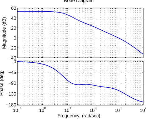
In Chapter 5 I describe the system identification and controller design for both types of feedback sensors used. An example of the plant open-loop dynamics is given in Figure 1-4. Here I consider the tradeoffs between analog and digital control archi-tectures, and ultimately make a case for the analog design that I actually implemented and tested. Also discussed are the final experimental results of the fully integrated system in both single- and dual-axis operational modes. I close the chapter by com-paring the test results to the original AFSM design goals. These results are given here in Table 1.1. A Bode plot of the system closed-loop performance at 10 kHz bandwidth is given in Figure 1-5.
Table 1.1: AFSM Measured Performance Characteristics
Performance Parameter Design Goal Measured Performance Bandwidth (Single Axis) 5 kHz 10 kHz
Bandwidth (Dual Axis) N/A 2 kHz
Angular Range ± 10 mrad ± 3.5 mrad Angular Acceleration 1 × 10⁵ rad/sec2 1x10⁵ rad/sec2
Angular Resolution 8.7 × 10⁻⁷ rad Variable
1 10 100 1000 10000 −60 −40 −20 0 20 40 Magnitude (dB)
Optical Plot, Azimuth, ±100 mV cmd in, Optical Volts Out
1 10 100 1000 10000 −540 −450 −360 −270 −180 −90 0 Phase (°) Frequency (Hz)
Figure 1-4: Azimuth closed-loop frequency response using the optical quad cell.
1 10 100 1000 10000 −40 −20 0 20 Magnitude (dB)
Closed Loop Elevation Plot, ±1.0 V cmd in, Optical Out
1 10 100 1000 10000 −540 −450 −360 −270 −180 −90 0 Phase (°) Frequency (Hz)
Chapter 6 concludes the thesis by offering suggestions for future work in the form of optimized designs for form factor, small signal bandwidth, etc. These designs seek to evolve the AFSM design, which was conceived purely as a technology demonstrator, into mature concepts that provide solutions for specific applications.
The final portion of this thesis consists of three appendices containing support-ing information. As previously mentioned, Appendix A provides a derivation of the AFSM actuator electromagnetic equations using Maxwell’s laws. Appendix B doc-uments the follow-up work I performed regarding the unexpectedly high stiffness characteristics discovered in the AFSM hardware during testing. Finally, Appendix C provides transfer function derivations for the analog controllers designed in Chapter 5.
1.2
Optical Communication Technology
In recent years, long-distance communication and data transfer technology through optical means has emerged as a potential replacement for traditional radio-based sys-tems [15]. In particular, such optical communication syssys-tems show promise as a se-cure, power-efficient means of data transmission between aircraft, spacecraft, and/or ground stations during military and scientific-exploration missions. In the last few years, NASA and the U.S. Air Force have both initiated programs to develop this tech-nology. The most notable effort to date has been the Mars Lasercomm demonstration program of 2005, in which MIT Lincoln Laboratory played a major development role. Despite the system-level benefits of enhanced power efficiency and security, long-distance communication through optical means introduces significant new technical challenges that must be overcome prior to the implementation of any practical system. One of these is the problem of beam pointing, acquisition, and stabilization. Unlike radio-based systems, which even for directional signals are characterized by beam angular dispersions of several degrees or more, the lasers proposed for use in optical systems have beam dispersions only a small fraction of this size. Despite being very power-efficient, the small dispersion greatly compounds the pointing problem. For
example, as determined during the Mars Lasercomm technology demonstration, in order to hit Earth from a Mars a laser beam originating from an orbiting satellite must be pointed within 400 nanoradians RMS error [11]. When contrasted with pointing error requirements on the order of tens of microradians for a radio system, it is apparent that the pointing precision for the optical beam is about ten to twenty times tighter than that required for a radio system.
Compounding the comparatively simple problem of static pointing, the main im-plication of reducing the pointing error budget is that previously inconsequential (i.e. “in-the-noise”) disturbance sources become significant, and must be addressed in the system design. For instance, in a satellite application, minute sources of mechani-cal vibration transmitted through structural components to the optimechani-cal system may introduce pointing errors of unacceptable magnitude. As described in Loney [15], vibration sources such as those from solar array drives and momentum wheel bearing noise vary widely in frequency and contain enough energy to introduce meaningful beam pointing errors. Hence, the optical pointing system must be robust enough to reject these disturbances over a wide frequency spectrum. As another example, a sim-ilar system installed on an aircraft experiences disturbances in the optical path arising from turbulent airflows over the aircraft exterior. Here, the disturbances are inher-ently random in both amplitude and frequency, and thus a robust, broad-spectrum active rejection system is required to eliminate the resulting errors.
1.3
Motivations for AFSM Development
To address the issue of broad-spectrum disturbance rejection, the system developed during the Mars Lasercomm technology demonstration at MIT Lincoln Laboratory in 2005 employed many separate components in a staged configuration. These are described in Hawe [11] and are shown in the simplified schematic given in Figure 1-6. As designed, the system was capable of rejecting spacecraft-generated disturbances on the order of microradian amplitude from DC to approximately 1 kHz, with an over-all closed-loop system bandwidth of about 2 kHz. Without delving into great detail,
4
Quad Cell
FSM
2 - 300 Hz active
DC - 0.02 Hz
Pointing & Tracking Architecture
FPA Beacon 0.02 - 2 Hz Earth MIRU MIRU
BLENDING TRACK LOOP DC – 2 HZ
> 300 Hz passive
Figure 1-1: Simplified MarsComm spacecraft signal path schematic, courtesy of Jamie Burnside.
25
Figure 1-6: Simplified Mars Lasercomm spacecraft optical component schematic (from Hawe [11]).
the system operation is as follows: After coarse spacecraft pointing via conventional methods (i.e., on-board gyroscopes, star trackers, and attitude control), the earth-based beacon laser signal is acquired by the telescope and projected onto the focal plane array (FPA), which provides angular position information from DC to about 2 Hz. In addition, angular rate sensors on board the magnetohydrodynamic inertial reference unit (MIRU) generate feedback information from 2-300 Hz. The MIRU also generates an inertially stable reference laser beam that is injected into the same telescope optics used to detect light signals from earth. The signals originating from both earth and the MIRU are reflected off the fast steering mirror (FSM), and the reflected MIRU signal is sensed by the quad cell detector. The quad cell is the feed-back sensor in a zero-reference control loop closed around the FSM, and with a sensor bandwidth of approximately 100 kHz, it is capable of measuring the remainder of the
disturbance spectrum. Because the reference beam from the MIRU is inertially sta-ble, any errors detected at the quad cell must be due to mechanical base disturbances in the spacecraft transmitted through one or more of the system’s optical compo-nents (note that no atmospheric disturbances exist due to the vacuum environment). The FSM control loop actively corrects for these errors by actuating the mirror in both azimuth and elevation. Hence, even though the main optical components in the system (for example, the telescope mirrors) may experience mechanical disturbances, the incoming and outgoing optical signals remain inertially stable due to the correc-tions provided by the FSM. Hence, the optical system is pointed and stabilized to the required accuracy, and is ready to transmit and receive data.
Although successful as a demonstration, the Mars Lasercomm technology is still subject to certain limitations. First, due to hardware limitations the active control system does not have sufficient loop gain to adequately reject all angular errors within the required frequency band. Therefore it is necessary to provide additional atten-uation by mounting the optical components on a passive isolation platform, which increases the system’s cost, mass, and complexity. A second, related problem is that the system bandwidth is not sufficient to reject the entire disturbance spectrum nec-essary to meet angular error requirements, which again requires the addition of a passive vibration isolation system to augment the active component.
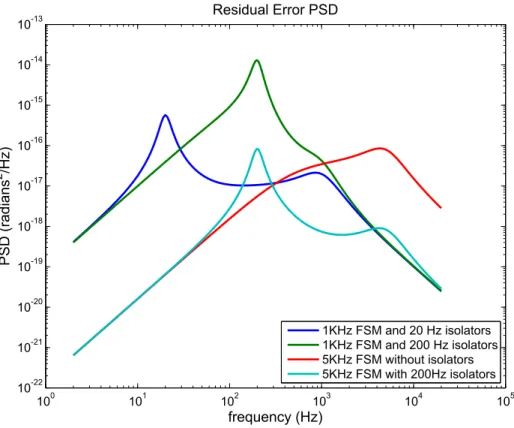
Specifically, the Mars Lasercomm investigators found that the existing FSM tech-nology used in the demonstration was a key contributing factor to both of these shortcomings, and concluded that the availability of a higher bandwidth FSM could yield a cheaper system with less complexity, yet have the same or better performance as existing designs. The results of one study into this issue are shown in Figure 1-7. Here, the power spectral density (PSD) in angular error of a conventional isolation system design consisting of a 1 kHz bandwidth FSM and passive platform isolators with 20 Hz resonant frequency is plotted (dark blue line) against several other cases. In the first case (green line), the existing FSM is maintained, but the resonant frequency of the passive isolators is changed to 200 Hz. Such isolators are cheaper, simpler, and more compact than a 20 Hz isolator, but provide far less attenuation of
100 101 102 103 104 105 10-22 10-21 10-20 10-19 10-18 10-17 10-16 10-15 10-14 10-13 Residual Error PSD frequency (Hz) PSD (radians 2 /Hz) 1KHz FSM and 20 Hz isolators 1KHz FSM and 200 Hz isolators 5KHz FSM without isolators 5KHz FSM with 200Hz isolators
Figure 1-7: Spacecraft pointing error PSD plots for various active and passive isolation cases. Plot courtesy of Jamie Burnside.
base vibrations. The result is that the FSM is subject to larger disturbance ampli-tudes, which may not be sufficiently rejected. Note that relative to the original case, the mid-band error rejection is very poor–almost four orders of magnitude worse in the 100-300 Hz range.
In the second case (red line), the 1 kHz FSM is replaced with a 5 kHz FSM and the passive isolators are removed completely. This represents the simplest and cheapest case. Here, it is evident that the error performance at low frequencies is superior by about three orders of magnitude to either of the prior configurations; however, it is worse by about two orders of magnitude at high frequencies due to the absence of the passive isolators.
The final case (light blue line) takes a middle ground, using the 5 kHz FSM and the cheaper 200 Hz isolators. This system provides the same superior rejection at low frequencies due to the high gain FSM, and aside from a small band around 200
Hz, it provides equal or better high-frequency performance relative to the original system. Thus, the system displays a net performance increase, despite being simpler and cheaper.
Studies such as this one prompted the search for new, alternative technologies for use in a flight system. In addition, the investigators desired a new FSM technology with performance sufficient to be useful for many years of anticipated future missions. Along with the space and airborne laser communication technologies mentioned pre-viously, use of the new FSM technology is foreseen in lidar systems and ground-based telescope adaptive optics, and also has application to industrial applications such as maskless photolithography for semiconductor manufacturing.
1.4
Discussion of Prior Art
The development of a proof-of-concept advanced fast steering mirror (AFSM) is the subject of this thesis. I describe in this and the following chapters the underlying technology, as well as my work designing, fabricating, and testing the prototype AFSM. Before beginning this discussion, however, it is prudent to review prior efforts in FSM design, as well as the enabling research that led to the design that I eventually built and tested.
1.4.1
Early Fast Steering Mirrors
Fast steering mirror technology has existed in various stages of sophistication for many years. The most basic technology; that is, a single axis mirror driven by a galvanometer1, has existed for decades, and is still widely used in many scientific and
industrial machines, such as bar code scanners, high speed product printing, medical imaging devices, and laser light show entertainment displays [5]. Two-axis operation
1A galvanometer is an electromagnetic actuator in which a current-carrying coil is placed in a
static magnetic field. It is similar to a voice coil, but is designed to provide a torque (via alignment of magnetic dipoles) rather than a linear force. Unlike typical rotating electric motors, galvanometers are designed for only a limited range of angular motion. Typically, the electromagnetic torque is counteracted by a restoring torsion spring.
may be achieved through the use of two such mirrors in a staged configuration. A photograph of a commercially available galvanometer from Cambridge Technology, Inc. is shown in Figure 1-8.
Figure 1-8: Cambridge Technology model 6400, a single-axis galvanometer.
Galvanometer-based mirrors typically feature very high angular travel (on the order of degrees to tens of degrees), but limited bandwidth. This tradeoff may be reversed by employing piezoelectric actuators to move the mirror, rather than the Lorentz-force electromagnetic principle used in the galvanometer. Piezoelectric de-signs, such as those marketed commercially by Physik Instrumente Corporation, fea-ture high stiffness, high bandwidth, and a simple mechanical configuration; however, they suffer from limited angular travel, high hysteresis losses, and require sophisti-cated high voltage drive amplifiers. For example, PI models such as the S-325 and S-330 have a closed-loop bandwidths of only 500 to 1000 Hz and an angular range of only 2 to 5 mrad. [23].
1.4.2
Recent Fast Steering Mirror Development
Fast steering mirrors for space applications have been developed in the past two decades, and a few designs have seen flight service. In particular, Ball Aerospace Company and MIT Lincoln Laboratory are frontrunners in this area. These designs
Figure 1-9: A fast-steering mirror which employs voice-coil actuation, built by Ball Aerospace Corporation.
represent the primary technology foundation that forms the basis for the AFSM design.
Ball Aerospace
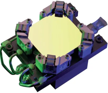
Over the past several decades, Ball Aerospace Corporation has produced a wide range of devices for air and space flight service, which vary in size, functionality, and performance [2]. The heritage Ball designs typically employ electromagnetic actuation via Lorentz-force (voice coil) drives. Mirror sizes are on the order of tens of millimeters, and typical published bandwidths range from 250 to 1000 Hz, with 1.5 kHz as the highest advertised bandwidth. The devices are typically are constrained to one or two degrees of freedom, with two being the most common. A picture of a typical Ball mirror design is shown in Figure 1-9.
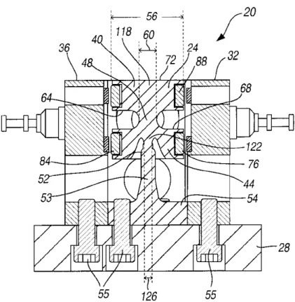
Through research and development, Ball has undertaken several interesting ex-plorations of FSM technology. One such development, detailed in U.S. Patent No. 6,612,192, is a single-frequency conical scanning mirror illustrated in Figure 1-10. This devices employs a mirror and reaction mass coupled together through
metal-Figure 1-10: Two-axis reaction-free scanning mirror developed by Ball Aerospace (image from Patent No. 6,612,192).
lic flexures, and is designed to be driven at the mechanical resonant frequency with opposing torques via Lorentz-force actuators. The acceleration of the reaction mass cancels the mirror accelerations, thus attenuating undesirable reaction forces into the base structure. Since the mirror is driven at resonance, very little power is required to maintain the scanning action [9].
As part of a separate research project, Ball also developed a fully levitated six-degree-of-freedom mirror, which is documented in several journal articles such as [20]. This mirror is unique in that it employs no flexures for kinematic constraint, and instead relies on active forces from a suite of eight voice coil actuators to levitate, center, and position the moving element. The absence of flexures greatly improves the angular range (± 87 mrad) and positioning accuracy, but comes at the price of a very complex MIMO control architecture and relatively high power consumption, even qui-escently, due to the need to actively levitate the moving mirror mass. The published
Figure 1-11: Cutaway view of the Lincoln Laboratory High Bandwidth Steering Mir-ror (HBSM).
small signal bandwidth was rather modest at 600 Hz; however, the prototype used a large mirror with a 5-inch aperture.
MIT Lincoln Laboratory
In contrast to Ball’s wide range of developments in FSM technology, FSM devel-opments at Lincoln Laboratory over the last two decades have been more tightly focused. Lincoln’s current suite of fast steering mirrors, several of which have seen flight service on various missions, are all based on original development work per-formed in the early 1990s by Gregory C. Loney. The mirror design has been dubbed the High-Bandwidth Steering Mirror (HBSM), and each subsequent design variant is given a letter designation. The current variant is the HBSM-D. Loney’s report, “High Bandwidth Steering Mirror Research”[15], became my primary reference for the AFSM design.
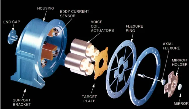
An exploded view of the Lincoln HBSM is shown in Figure 1-11. In this figure the key components which provide the mirror’s functionality are illustrated. At the
heart of the device are four linear voice coil actuators, which operate on the four quadrants of the moving assembly, with opposite pairs of actuators in a push-pull configuration. To reduce moving mass, the actuators are designed with stationary magnets and cores, and moving coils. The moving coil heads are bolted through a target plate and flexure ring to the mirror holder, which is the main dynamic structure and is manufactured from beryllium. The polished mirror is bonded to the mirror holder. Kinematically, the mirror holder is constrained in torsion and the two lateral translational directions by the flexure ring, and in the axial translational direction by the central axial flexure. Both the axial flexure and flexure ring are made of stainless steel.
Position sensing is accomplished via four eddy current sensors (sometimes called “Kaman sensors” in reference to their manufacturer, Kaman Measuring Systems), which measure the linear distance to the four lobes of the target plate sandwiched between the mirror holder and voice coil heads. All components are supported struc-turally by a common housing.
In the documentation of his original design, Loney demonstrates good perfor-mance numbers, albeit for a small mirror apertures of 10 and 16 mm. The published performance for the prototype design is given in Table 1.2. Subsequent flight designs using larger mirrors and higher design margins operated with reduced performance numbers.
Table 1.2: HBSM-B Prototype Measured Performance Property HBSM-B Performance Bandwidth (-3 dB) 10 kHz
Angular Range ±13 mrad Angular Resolution 0.2 µrad Angular Acceleration 1.3x10⁴ rad/sec2
Mirror Aperture 10-16 mm Mirror Construction Beryllium
1.5
AFSM Performance Goals and Design
Con-straints
The prior art fast steering mirror designs described in the previous section, while adequate for their intended missions, may not meet the needs of future high-precision optical applications. The goal of this thesis is to demonstrate new AFSM technology that offers a significant improvement in performance over prior designs–most notably in bandwidth and acceleration–and thus improves robustness and flexibility at the system level.
To this end, the original AFSM funding proposal identified the performance goals listed in Table 1.3. As a basis for comparison, the proposal referenced the performance characteristics of the present Lincoln Laboratory HBSM-D design. Note that the D variant is designed with a bigger mirror and larger design margins than the prototype B variant, and thus represents a typical-performance heritage design. In his Master’s thesis, Larry Hawe [11] provides details measurements of the HBSM-D performance and explored several different control schemes for an optical system using this mirror.
Table 1.3: AFSM Proposal Performance Goals
Property AFSM Proposal Goal HBSM-D Performance
Bandwidth (-3 dB) 20 kHz 1-2 kHz
Angular Range ±20 mrad ±10 mrad
Angular Resolution 5x10⁻⁸ rad 1x10⁻⁵ rad Angular Acceleration 106 rad/sec2 104 rad/sec2
Mirror Aperture 30-60 mm 15-100 mm
Mirror Construction Beryllium Beryllium
1.5.1
Limitations of Existing Technologies
To assess whether such an advance in performance is feasible, it is helpful to under-stand the limiting characteristics of the prior art designs. As discussed in Section 1.4, these designs are categorized based on the actuation principles they employ:
Elec-tromagnetic, as in the voice coil or galvanometer designs, and piezoelectric. Other actuation principles, such as magnetostriction and electrostatics, are not in wide use and are therefore not considered here. In his PhD thesis, Lu [16] provides an excellent review of the physical limits of the two main prior art technologies, particularly with regard to force output and bandwidth. His findings are summarized below:
• Lorentz Force Actuators: Moving coil actuators (voice coils and galvanome-ters) based on the Lorentz force are inherently limited in peak force output due to thermal constraints; that is, the metallic conductors used in voice coil design (most commonly copper or aluminum) are subject to maximum current density levels above which the coil overheats. Using established empirical ther-mal limits, Lu calculates that an ideal air-cooled aluminum coil with no other attached mass loads can sustain maximum accelerations of 109 G (where G is the acceleration due to earth’s gravity). The more common copper coil fares much worse, with a maximum acceleration of 42.7 G.
Although the thermal limitation may be alleviated through the use of convective cooling methods, especially liquid cooling, any practical implementation of such a system will add mass to the coil and tend to counter the resulting gains in allowable current density. Another alternative is to use superconductors in place of the traditional metallic conductor, or to increase the flux density of the external magnetic field in which the coil acts; however, at the time of this writing, superconductors are technologically viable only for the most exotic and expensive applications (such as magnetically levitated trains). Another limitation of superconductors is that they are intolerant of rapid changes in flux density, and are therefore unsuitable for high-bandwidth dynamic applications. Also, flux densities are limited by currently available materials. For example, the best available permanent magnets are limited to a remanence of 1.4 to 1.5 tesla, while the best soft magnetic materials, carrying a flux induced from an electric coil, saturate at about 2.0 tesla.
are generally characterized by short strokes and relatively high bandwidths. However, a piezoelectric stack is inherently limited by its own internal electrical and mechanical losses, which have the effect of reducing stroke output (and hence, bandwidth) as frequency increases. Thus, direct drive devices are usually limited to bandwidths of around 1 kHz.
Another problem with piezoelectric actuators is the difficulty of building long-stroke devices. Because the proportionality of strain to applied voltage is so small (about 0.1%), increasing the available stroke usually involves the use of a lever-type mechanical amplifier. PI offers a fast steering mirror design, the model S-334 that employs this technique to achieve an angular stroke of 50 mrad. However, doing so adds mass, and the overall stiffness is reduced due to the transmission ratio N2 and the compliance of the lever. Both of these
complications tend to reduce the available bandwidth, and thus, a tradeoff between stroke and bandwidth becomes necessary if the decision is made to use piezoelectric actuators. The S-334, for example, has a bandwidth of only 800 Hz.
In addition to the voice coil actuators, Loney reports in [15] that the metallic flexures used in the HBSM designs also reduced performance. In the original design iterations, the flexures were undamped, and the resonances of the long slender beam members coupled directly into the angular output of the mirror. The first of these parasitic modes occurred around 2 kHz, which limited the achievable bandwidth. The problem was mitigated by redesigning the flexure and adding a layer of viscoelastic damping epoxy to the part. Refer to Hawe [11] for additional details.
1.5.2
Enabling Technologies
As it turns out, two of the contemporary research areas taking place at the Precision Motion Control lab at MIT provided solutions for both the actuator force limitations, and also the problematic metallic flexure resonances.
steering actuator configuration that he successfully employed in a single degree-of-freedom fast tool servo system. The actuator relies on normal force principles similar to a solenoid, but has the advantage of being nearly linear in both current and stroke, thus making it easy to control. In his thesis [16], Lu performs a theoretical calculation to show that the accelerations attainable on a steel armature for practically attainable flux densities is up to 4000g, which is 100 times that of the copper voice coil ( 40g). Also, the actuator configuration lends itself well to stroke ranges of about 10 to 1000 microns, which falls between a piezoelectric actuator (micron-order) and voice coils (millimeter-order). This combination of stroke and force is ideal for the fast steering mirror application.
The second area of research, spearheaded by Augusto Barton and David Cuff as part of their Master’s theses ([17], [6]), was the use of viscoelastic materials (specif-ically, elastomers such as neoprene and silicone) as kinematic bearings in place of traditional metallic flexures. The use of such bearings involves many tradeoffs, as ex-plained in Chapter 2; however, they do provide immediate solutions to the problems encountered by Loney with his metallic flexure design–namely the extra modes and lack of damping.
1.6
Final Performance Goals
The initial proposal goals listed in Table 1.3 were based on the theoretical analysis performed by Trumper and Lu. As part of the proposal, I assessed the performance of a practical device relative to the theoretical numbers and came to the conclusion that although achievable, the project scope to attain the full proposal performance was too large for both the allocated time schedule (approximately 9 months) and available funding. My assessment was based on the fact that considerable design op-timization through numerical analysis was necessary, coupled with the fact that the resulting design would require exotic materials and expensive manufacturing tech-niques. I concluded that the funding and schedule would be better suited to the reduced performance specification given in Table 1.4. By demonstrating this basic
level of performance, the project would serve as a demonstration of the fundamental technology from which future optimized designs could be based.
The AFSM hardware described in the remainder of this thesis is designed to meet the performance goals listed in Table 1.4.
Table 1.4: AFSM Prototype Performance Goals Performance Parameter Design Goal
Bandwidth 5 kHz
Angular Range ± 10 mrad Angular Acceleration 1 × 10⁵ rad/sec2
Angular Resolution 8.7 × 10⁻⁷ rad Mirror Aperture 20 mm Mirror Construction Aluminum
1.7
AFSM Operational Concepts
Before discussing the mechanical and electromagnetic details of the AFSM design, I provide in this section an overview of the basic hardware configuration and opera-tional concepts. This discussion may be used as a point of reference for the analysis presented in subsequent chapters.
A CAD rendering of the final AFSM design iteration is shown in Figure 1-12. The mirror which comprises the heart of the optical system is located in the center, and is drawn in red. The two principal actuated degrees of freedom, θx and θz, are indicated
by the dashed lines running through the mirror center.
Arrayed around the mirror are four identical actuators, which act on magnetic armatures bonded to the mirror edges. Each actuator applies a force to the arma-tures (and hence, the mirror edges) in either the positive or negative Y direction. By applying equal and opposite forces at opposing actuator edges, a torque is developed which moves the mirror in one or both actuated DOFs. Both the mirror and actu-ators are mounted to the machine base, which provides structural support for the entire assembly. The actuators are rigidly mounted to the base, while the mirror is
Mirror
Magnetic Actuator
Normal Force
Machine Base
θ
zθ
xX
Y
Z
Figure 1-12: Isometric CAD rendering of the AFSM showing the actuators arrayed around the central mirror. The dashed lines indicate the rotation axes of the mirror.
suspended relative to the base by a set of flexures.
A clearer understanding of the AFSM’s internal operation can be obtained by viewing Figure 1-13, which illustrates the AFSM hardware in cross-section. This view is obtained by conceptually slicing Figure 1-12 vertically through either the θx or θz
axis. Here the internal components of the actuators are revealed, as well as the flexure support structure for the mirror. There are two types of flexures, which in concert constrain the four non-actuated DOFs. The axial flexure constrains the mirror in the Y translation DOF, while the four elastomeric flexures constrain X and Z translation and θy rotation (note that two of the four elastomeric flexures are out-of-plane and are
therefore not shown). Also illustrated are the capacitance probes that measure the mirror displacements relative to the housing, and the associated clamping mechanism that holds them in place. The mechanical assemblies and design are covered in greater detail in Chapters 2 and 4.
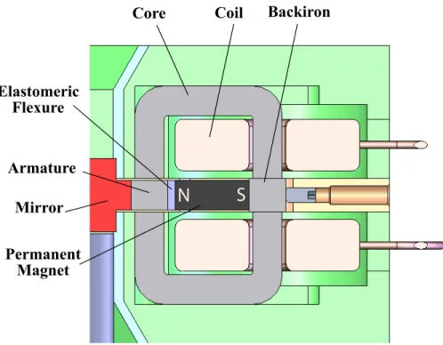
The architecture of one of the AFSM actuators is displayed in Figure 1-14. The actuator consists of two symmetric halves, upper and lower, each of which contain an electrical coil wrapped around a magnetically permeable core. Each coil and core is rigidly potted in place to the actuator housing, which is displayed in green in the figure.
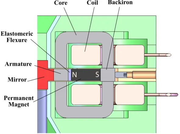
Between the two actuator halves is a backiron piece which mounts flush against the rear pole faces of the cores. This piece provides a return path for the magnetic fluxes generated in the cores. At the heart of the actuator is a powerful neodymium-iron-boron (NdFeB) permanent magnet. The magnet provides a biasing magnetic flux to the armature. The DC flux from the magnet is steered to one core half or the other by the superposed flux from the electrical coils. For a more detailed treatment of the actuator operation, see Chapter 3.
With the basic layout and operational principles in hand, I now proceed with the detailed design treatment. The mechanical design elements are discussed in the following chapter, while the electromagnetic actuators are analyzed in Chapter 3. The full mirror assembly and supporting hardware are discussed in Chapter 4.
SS
Coil
Permanent
Magent
Elastomeric
Flexure
Armature
Core
Mirror
Capacitance
Probe
Housing
Probe
Clamp
Axial Flexure
Base
N S
N S
Figure 1-13: Cross-sectional view of the AFSM showing the mirror, flexure supports, capacitance probes, and actuators.
Armature
Core
Coil
N
S
Permanent
Magnet
Elastomeric
Flexure
Mirror
Backiron
Chapter 2
Mechanical Design
A successful mechanical design is the fundamental factor which determines the ulti-mate performance of the AFSM system as a whole. The primary design emphasis must be mechanical, because the system output in terms of optical beam direction and stability is directly determined by the speed and precision with which the mechanical components are positioned. This may seem like a trivial statement until one considers the large dynamic range under which the mechanical system must perform. When considering precision mechanical operations through frequencies spanning tens of kilo-hertz, the simplifying assumptions of rigid body dynamics employed in most machine designs become inadequate. The true flexible body dynamics not only contribute to high-frequency positioning errors, but may also destabilize the control system if not identified and addressed in the system design. Also, since the actuators, sensors, and electronics comprising the remainder of the system function solely to drive, measure and compensate the mechanical elements, the AFSM design must begin here1.
2.1
Control System Considerations
Before delving into the mechanical design details, however, it is prudent to take the broader viewpoint of the control systems engineer, and consider the influence
1Moreover, since I am a mechanical engineer by training, I am motivated by my misguided sense
of the mechanical plant on the remainder of the AFSM system. The accuracy and bandwidth performance requirements for the AFSM design necessitate the use of closed-loop control to improve the natural dynamics of system. A critical step in a successful controller design is the mathematical derivation, and eventual experimental verification, of an accurate open-loop dynamic model of the mechanical plant to be controlled. However, given that the design is brand new, an opportunity exists not only to simply identify the natural dynamics, but to actually prescribe them in an advantageous way, such that a simple controller can be used to achieve the required performance. This is done, of course, by performing the mechanical design with the desired dynamics as initial design goals.
A key insight gained from studying control systems theory and systems modeling is that as the disparity between the natural plant dynamics and the desired open-loop dynamics increases, the difficulty of designing a compensator to achieve the desired performance increases proportionally. Furthermore, even though the designer may ar-rive at a controller design that appears tractable mathematically, physical hardware limitations (for example, amplifier saturation) may make practical implementation of the design difficult if not impossible. Conversely, however, if the natural plant dynam-ics are very close to the desired dynamdynam-ics, designing and implementing a successful control architecture becomes a straightforward task.
As an example, consider the plant described by the following equation, and the Bode plot given in Figure 2-1.
G(s) = 1 × 10⁵ s
3
(s + 10)3(s + 100)2 (2.1)
This plant represents an AC-coupled system; that is, a system with zero response at DC (zero frequency). An example of a physical AC-coupled system is an electrical transformer. Since its output relies on the establishment of a time-varying magnetic field within the input and output windings, applying a DC signal to the input produces no output. In the example above, the plant dynamics contain the combined output of several AC-coupled systems, which together produce the three zeros at the origin2.
−150 −100 −50 0 50 Magnitude (dB) Bode Diagram Frequency (rad/sec) 10−1 100 101 102 103 104 −180 0 180 360 Phase (deg)
Figure 2-1: Example of an AC-coupled system
Suppose we wish to control this system across a bandwidth spanning from DC to 1000 rad/sec. From a pure mathematical standpoint, this may be accomplished without great difficulty. We simply use three poles at the origin to cancel the plant zeros, and three zeros in the mid-band to boost the system gain around these fre-quencies. Finally, we add a lead network for high frequency phase margin, and adjust the controller gain for the appropriate crossover. The transfer function for one such controller is
C(s) = 23(s + 20)
2(s + 50)(s + 200)
s3(s + 2000) (2.2)
which when combined with the plant model results in the compensated system loop transmission shown in Figure 2-2. The compensated system displays excellent gain in all frequencies from DC through crossover, and a robust phase margin of about 55 degrees at 1000 rad/sec.
Unfortunately, physically implementing the controller as designed is quite
−40 −20 0 20 40 60 Magnitude (dB) 10−1 100 101 102 103 104 −180 −135 −90 −45 0 Phase (deg) Bode Diagram Frequency (rad/sec)
Figure 2-2: A mathematically tractable, but physically impossible control scheme for the AC-coupled system
sible! The trouble lies in our attempt to cancel the three zeros at the origin with controller poles. Remember that physically, the fact that the system is AC-coupled means that it produces zero output at DC, regardless of the magnitude of the input. Here, by using the three integrator poles at the origin, we have designed a controller that attempts to apply an infinite control effort to the system to produce a finite output–which is, of course, impossible. In terms of control theory, we have made the plant poles unobservable in the feedback measurement. In a real system, applying a DC reference command would quickly drive the three integrators into saturation, most likely at the power amplifier. Since the saturation level is finite, the system output would be zero.
This example also illustrates the prior point about the physical difficulties of using a controller to modify the plant dynamics. In reality, since we cannot use pure integrators to simply cancel the plant zeros, we would instead use a triple-lag controller, with poles at low (but nonzero) frequencies, to widen the controlled frequency band as much as possible. However, as the lag poles are moved lower in
frequency, the control effort required to produce meaningful output at that frequency increases. Eventually we will reach a point where the physical limitations of the control hardware do not allow further reduction in the band pass frequency–and even if physically possible, the controller (specifically, the power amplifier) would likely be very expensive and consume a large amount of power.
2.2
Mechanical Design Goals
With these insights in mind, we return to the AFSM mechanical design. Here, to make the plant as controllable as possible, it is desirable to achieve several goals. First, since the mirror is controlled in two degrees of freedom, creating a mechanical design that decouples these degrees of freedom allows the use of two independent single-input, single-output (SISO) controllers rather than a more complex multi-input, multi-output (MIMO) architecture. The advantages of SISO controllers are numerous, but their most important characteristic is the fact that they can be readily designed using experimental frequency response model data. In addition, it is far easier to design and verify a robust controller using SISO techniques.
If we consider the situation from a purely mathematical standpoint, it may be tempting to ask why such an emphasis on mechanical decoupling is warranted. After all, if the controlled system is linear, it should be possible to apply a transformation matrix to the two signals in order to decouple them and thus treat them separately. However, the downfall again comes when trying to implement such a transformation practically. First, for the transformation to be valid, the mathematical model of the plant must be very accurate–which may not be true for many real systems, or sys-tems subject to varying plant parameters. Second, implementing the transformation requires additional complex circuitry in an analog system, or more computation time over the sampling interrupt in a digital system. More importantly, the outputs from the transformation itself may require a large percentage of the system’s limited con-trol authority, and therefore in turn limit the overall concon-trol performance. It is far better then to perform the decoupling mechanically, so that we can take advantage