Achromatic and Wide Field-of-View Metalens
Design
by
Fan Yang
B.S., Peking University (2019)
Submitted to the Department of Materials Science and Engineering
in partial fulfillment of the requirements for the degree of
Master of Science in Materials Science and Engineering
at the
MASSACHUSETTS INSTITUTE OF TECHNOLOGY
February 2021
c
⃝ Massachusetts Institute of Technology 2021. All rights reserved.
Author . . . .
Department of Materials Science and Engineering
January 15, 2021
Certified by . . . .
Juejun Hu
Associate Professor
Thesis Supervisor
Accepted by . . . .
Frances
M. Ross
Chair,
Departmental Committee on Graduate Studies
Achromatic and Wide Field-of-View Metalens Design
by
Fan Yang
Submitted to the Department of Materials Science and Engineering on January 15, 2021, in partial fulfillment of the
requirements for the degree of
Master of Science in Materials Science and Engineering
Abstract
Achromatic and wide field-of-view (WFOV) optical functionalities are desired for var-ious imaging applications. Conventional methods use complicated design approaches or assemble multiple optical components to form achromatic and WFOV lenses. They are bulky and have limited focusing quality. Here a novel metalens design is presented which shows extraordinary achromatic and WFOV focusing quality simultaneously. The metalens is composed of all-dielectric atoms selected from a large meta-atoms library with diverse dispersion behavior. The metalens and an aperture are integrated on opposite sides of the substrate to separate areas with different angle-of-incidents (AOIs). A theoretical analysis and a direct search algorithm are combined to obtain optimum phase profile of metalens. This design concept is generic and can be applied to lenses with different parameters to meet the demands of various applications.
Thesis Supervisor: Juejun Hu Title: Associate Professor
Acknowledgments
First of all, I would like to thank my advisor, Prof. Juejun Hu. He offered me a lot of guidance to complete this project. Also, I benefited from him a lot with his creative ideas and learning materials during the whole academic period.
I would like to thank my group mate, Dr. Tian Gu and collaborator, An Sensong for their help in this project. I would also like to thank everyone in Photonic Materials Group and Electronic Materials Group for giving me help and suggestions. I had wonderful experience with the accompany of my group mates.
I would like to thank Prof. Juejun Hu and DMSE to continuously support me in the Covid period that ensures the progress of my academic achievements and this project.
Finally, I would like to thank my parents, my group mates and my undergraduate friends who offered me support and gave me advice in the time of difficulty.
Contents
1 Introduction 15
1.1 Motivation of the project . . . 15 1.2 Design challenges and solutions . . . 16
2 Metalens design approach 19
2.1 Meta-atom design . . . 19 2.2 Direct search algorithm . . . 21
3 Achromatic and WFOV metalens 25
3.1 Achromatic metalens . . . 25 3.2 WFOV metalens . . . 32 3.3 Achromatic and WFOV metalens . . . 40
List of Figures
2-1 (a) Example of a 3D view of meta-atom structure. White part rep-resents high-index dielectric P bT e meta-atom, black part reprep-resents low-index BaF2 substrate. (b) Top view of 6 meta-atom structures.
Every mesh represents a 1× 1 pixel. Colored rectangles represent ‘Needles’ that are randomly generated to compose meta-atom struc-ture. To speed up simulation, mirror conditions are assumed along x and y directions, only the top-left quadrant is used in the simulation. 20 2-2 Phase coverage of meta-atoms. Blue dots represent simulated results
of different meta-atoms. Radial axis: transmittance. Angular axis: Phase shift (degree). . . 21 2-3 Illustration of Kirchhoff diffraction integral. Reprinted from [1]. . . . 22 2-4 Flow chart of direct search algorithm. . . 23 3-1 Achromatic metalens structure. Different colors stand for different
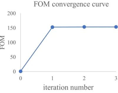
wavelengths, they all focus on the same focal spot. . . 26 3-2 FOM with increasing iteration times. The initial FOM is normalized
to be unity. It converges quickly after a few iteration times. . . 28 3-3 (a)-(c) Normalized 1D intensity profiles at image plane with incident
wavelength of (a) 6 µm, (b) 7 µm and (c) 8 µm. Blue lines show results from achromatic metalens, red lines correspond to results from lens optimized at certain wavelength with hyperbolic phase profile. (d)-(f) Normalized 2D intensity profiles at image plane with incident wavelength of (d) 6 µm, (e) 7 µm and (f) 8 µm. . . . 28
3-4 Image quality characterization of achromatic metalens. (a) FWHM plot with wavelengths. Blue dots come from achromatic metalens, red dots are acquired from lens optimized at certain wavelength as comparison. (b) Efficiency plot with wavelengths. (c) Strehl ratio plot with wavelengths. The red dashed line corresponds to diffraction limit with Strehl ratio = 0.8. . . 29 3-5 Sample image placed in front of metalens. Image taken by Ref. [31] . 29 3-6 Comparison of image quality captured by lens optimized at center
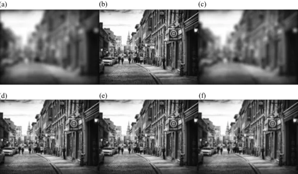
wavelength and the designed achromatic metalens. (a)-(c) Images from monochromatic lens at wavelength of (a) 6 µm, (b) 7 µm and (c) 8 µm. (d)-(f) Images from achromatic metalens at wavelength of (d) 6 µm, (e) 7 µm and (f) 8 µm. . . . 30 3-7 Phase profiles of achromatic metalens at wavelength of (a) 6 µm, (b)
7 µm and (c) 8 µm. Red lines show optimum hyperbolic phase at the specific wavelength. Blue lines show phase profiles of achromatic metalens. . . 31 3-8 Case examples of meta-atoms’ dispersion behavior for achromatic
met-alens. Selected wavelengths range is highly dispersive to partially com-pensate chromatic propagational phase differences. . . 31 3-9 (a) Efficiency and (b) Strehl ratio of designed achromatic metalens
(blue curve) and diffractive lens (red curve). . . 32 3-10 Schematic illustration of WFOV metalens design. (a) 3D-view. (b)
Side view. Reprinted from [2]. . . 33 3-11 Schematic illustrations of focusing process. (a) Two parallel beams
focus at the same position. (b) Beams with different AOIs share same area of metalens but focus at different positions. . . 36 3-12 Comparison of (a) focal spot position and (b) metalens’ phase profile
from theoretical analysis (red lines) and direct search algorithm simu-lation (blue lines). In figure (a), the two lines are so close to each other that it’s difficult to distinguish them. . . 37
3-13 Normalized one-dimensional field intensity on image plane along the line parallel to incident light beam plane with AOI of (a) 0o, (b) 30o,
(c) 60o and (d) 90o. Red lines correspond to lens with phase
opti-mized at the certain AOI. Blue lines correspond to intensity profile from designed WFOV metalens. . . 38 3-14 Normalized two-dimensional field intensity on image plane with AOI
of (a) 0o, (b) 30o, (c) 60o and (d) 90o. . . 39 3-15 Metalens (a) focusing efficiency and (b) Strehl ratio with increasing
AOIs. The red dashed line corresponds to diffraction limit with Strehl ratio = 0.8. It exhibits high focusing quality up to 90o incidence. . . . 39
3-16 (a)(b) Effects of NA on average efficiency and Strehl ratio among the WFOV by changing (a) focal length and (b) aperture size. (c) Effects of substrate thickness on average efficiency and Strehl ratio. . . 40 3-17 (a)-(c) Intensity profiles at AOI = 0oand (a) λ = 5 µm, (b) λ = 6 µm,
(c) λ = 7 µm. (d)-(f) Intensity profiles at AOI = 90o and (d) λ = 5 µm, (e) λ = 6 µm, (f) λ = 7 µm. . . . 43 3-18 (a) Efficiency and (b) Strehl ratio at different wavelengths and AOIs. 43
List of Tables
3.1 Achromatic metalens parameters . . . 26 3.2 WFOV metalens parameters . . . 34 3.3 Achromatic and WFOV metalens parameters . . . 41
Chapter 1
Introduction
This chapter introduces motivation of the project and challenges that are to be solved.
1.1
Motivation of the project
Metasurfaces are composed of arrays of sub-wavelength structures which modify phase, amplitude and polarization of light for image applications.[3][4][5][6] These meta-atoms resonantly coupled to the electric field or magnetic field or both of them from incident light and modify its optical properties. With this feature, by careful-ly designing meta-atoms structures and their distribution on the planar surface, the wavefront shape can be modified at will. This is in contrast with traditional opti-cal components where the phase is gradually accumulated through the propagation during refraction or reflection, which makes normal optical devices bulky, heavy and costly. On the other side, the ultrathin thickness of metasurfaces circumvent all these problems. Their fabrications are compatible with current lithography or nanoprinting methods. Also, since different meta-atoms can be designed to have different structures and thus different optical responses, this greatly enlarged degree-of-freedom (DOF) enables special functionalities that are not achievable by conventional devices. There-fore, metasurfaces show wide applications in recent years and exhibit great potential of substituting their bulky counterparts.
gradual-ly substituting their traditional optical lenses counterpart due to their light-weight, small size, cost effectiveness, increased design freedom and high focusing quality.[7] With years of development, metalens now exhibit extraordinary monochromatic focus-ing capability at normal incidence.[8][9][10] Under these circumstances, meta-atoms modify the phases to have a hyperbolic behavior that compensates the phase differ-ence between the lens’ edge and center.[11][12] In this case, the phase shift brought by the metalens is similar to the one brought by a common diffractive lens through propagation inside the refractive material.
This design, however, face chromatic and angle-dependent aberrations under broad-band illumination and none-zero AOIs. The hyperbolic phase is optimized at a single wavelength, it cannot compensate propagational path difference due to an extra of dispersion term. This makes light of different wavelengths focus at different positions along the axis and causes the chromatic aberration.[13] On the other side, even un-der monochromatic illumination, there are still angle-dependent aberrations. Several types of angle-dependent aberrations exist, including coma, astigmatism and field-curvature.[14][15] Under WFOV illumination, lights of different AOIs have different focal length, even under same AOI, they are refracted by different areas of the lens and they focus at different positions on the image plane. Typically, a conventional hyperbolic phase profile enables diffraction-limited focusing quality with AOIs up to 7o.[2] These limitations restrict their performance in the imaging applications where
broad bandwidth and WFOV are highly desirable.
This brings the motivation of the project. A metalens combining unprecedented achromatic and WFOV features will be designed to solve the aberration issues for all kinds of applications.
1.2
Design challenges and solutions
Several metalens designs have already be implemented to solve chromatic aberra-tions [16][17][18][19] and angle-dependent aberraaberra-tions [2][20][21][22]. However, some of them sacrifice metalens’ advantage of easy fabrication by assembling multiple plane
structures, some of them exhibit limited imaging quality. Also, there lacks a versa-tile method to achieve continuous achromatic and WFOV imaging simultaneously with high efficiency. The main limitation behind it is the different phase profile re-quirements under different conditions. When the metalens is designed for certain wavelength and AOI, its phase profile is uniquely optimized under that condition. Therefore, it’s inherently not suitable for other conditions. All the approaches try to solve this issue by modifying phase profile to make it do not deviate too much from the optimum one under all kinds of conditions. However, this process remains a huge challenge.
To solve these issues, a novel metalens with achromatic and WFOV features at the same time is presented here. It combines a machine-learning based meta-atom design approach and direct search algorithm to produce metalens layout. Compared with other design approaches, it retains unique advantages of metalens while showing extraordinary imaging quality. Also, the design structure and algorithm used have DOF, they are suitable for a wide variety of applications.
A typical metalens design is composed of three parts: meta-atom design, metalens structure design and phase profile design. Chapter two analyzes machine-learning based design of meta-atoms that compose metalens and the direct search algorithm that is used to produce metalens’ phase profiles. Chapter three first presents results of achromatic and WFOV metalens respectively, then follows results of metalens achieving both achromatic and WFOV features. The conclusions and outlook are finally drawn at Chapter four.
Chapter 2
Metalens design approach
2.1
Meta-atom design
Meta-atoms are subwavelength structures that modify phase, amplitude and polariza-tion of incident light. When light incidents on meta-atoms, its electric and magnetic field cause resonance of the meta-atoms’ material, creating electric dipole, magnetic dipole and other higher order multipolar resonances. These dipoles serve as secondary point sources that emit light with modified optical properties. The resonance behav-ior is controlled by the shape, material and arrangement of meta-atoms. Typically, regular shapes like cubic and cylindrical rods with varying in-plane dimensions and heights are used for simplicity consideration. In this case, the resonant behavior is mainly controlled by the first order of electric and magnetic dipoles.[23][24] By chang-ing their sizes, these meta-atom designs are able to cover the 2π phase range to fulfill the requirement of assembling metasurfaces. However, a large meta-atoms library with complicated meta-atom structures is needed in designs that require special func-tionalities, which is the case here. Also, the amplitude of the meta-atoms should be as close as unity so that the metalens can have high focusing quality. Specific to the case of achromatic metalens, meta-atoms should exhibit different phase shift at different wavelengths to account for the dispersion along the propagation path. Therefore, meta-atoms with large dispersion in the operational wavelengths range is highly desired.
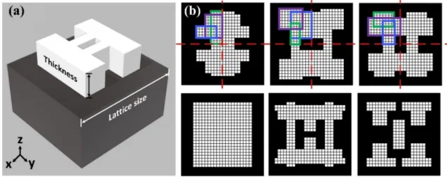
The meta-atoms design is conducted by one of my group mates. A short de-scription is presented here. The meta-atom structure is shown at Fig. 2-1. The all-dielectric meta-atoms are composed of 1 µm thick P bT e on BaF2 substrate with
the unit-cell size of 4× 4 µm2. P bT e has high refractive index of around 5 in the
interested wavelengths range, therefore, it can offer diverse dispersion behavior.[25]
BaF2 is chosen to be the substrate since it’s transparent in the wavelengths range.
A total of more than 10,000 meta-atoms are created with the 2D patterns generated within the square canvas (64× 64 pixels). The transmission and phase shift of meta-atoms are simulated with commercial FEM simulation tool - CST STUDIO SUITE. To make simplification, open boundary conditions are applied at the unit-cell bound-ary with x-polarized plane wave illuminates from the substrate side. This assumption is valid since a minimum spacing of 8 pixels is applied between adjacent meta-atoms to minimize inter-cell coupling.
Figure 2-1: (a) Example of a 3D view of meta-atom structure. White part repre-sents high-index dielectric P bT e meta-atom, black part reprerepre-sents low-index BaF2
substrate. (b) Top view of 6 meta-atom structures. Every mesh represents a 1× 1 pixel. Colored rectangles represent ‘Needles’ that are randomly generated to compose meta-atom structure. To speed up simulation, mirror conditions are assumed along x and y directions, only the top-left quadrant is used in the simulation.
The phase coverage of meta-atoms is shown at Fig. 2-2. It covers the whole 2π rad phase range with relatively high transmittance. These meta-atoms will serve as the library for the following achromatic and WFOV metalens design.
Figure 2-2: Phase coverage of meta-atoms. Blue dots represent simulated results of different meta-atoms. Radial axis: transmittance. Angular axis: Phase shift (degree).
2.2
Direct search algorithm
Direct search algorithm[26][27][28] is used to generate optimum metalens phase profile. It deviates from traditional hyperbolic phase to suppress aberrations from achromatic focusing or large AOIs. A proper figure-of-merit (FOM) is first defined depending on specific metalens functionality and requirement. For example, it can be the average intensities at the focal spot of different wavelengths for the broadband metalens de-sign, or it can be the average intensities of different AOIs for the WFOV metalens design. This will be discussed in detail in the following section. Generally speak-ing, it should be proportional to the device’s capability of satisfying the requirement. The goal of the direct search algorithm is to maximize FOM by designing optimum metalens’ phase profile.
po-sition on the image plane: e U (P ) = −i λ ∫∫ ⊂⊃ 1 2(cosθ0+ cosθ) f U0(Q) 1 r e ikr dS (2.1)
Figure 2-3: Illustration of Kirchhoff diffraction integral. Reprinted from [1]. The illustration is shown at Fig. 2-3[1] No near field nor paraxial approximation is used here since large numerical aperture (NA) and AOI are considered. When applying it to the metalens, the integration is substituted by the summation of the contribution from every meta-atom. This is valid since the spacing of meta-atoms is at sub-wavelength scale. The diffraction integral can be simplified into:
e U (P ) = −i λ ∑ N 1 2(cosθ0+ cosθ) f U0(N )ΦN 1 re ikrΛ2 (2.2)
Here, N denotes the index of meta-atoms and Λ is the spacing of meta-atoms.
f
U0(N ) stands for the initial phase that is incident on the meta-atoms and ΦN is the
extra phase change brought by the meta-atoms which is determined by the certain meta-atom design.
The flow chart of the direct search algorithm is shown at Fig. 2-4. It starts with generating a random phase profile and calculates the initial FOM. Then, it traverses all the atom positions. For every atom position, different meta-atom designs are tried and the one with highest FOM is chosen. The FOM after one iteration is then calculated to obtain the improvement. This process can be performed multiple times until certain ending criterium is reached, meaning it satisfies
the requirement.
Figure 2-4: Flow chart of direct search algorithm.
This seems to be a brute force method, but it turns out it doesn’t need heavy computational load as may be imagined. Several aspects help improve computational efficiency. First, angular symmetry of metalens can be assumed for most of appli-cations since normally equal efficiency at different directions is desired. This means traversing all meta-atoms on the metalens is not actually necessary. Rather, only traversing of a single line along the radius is needed. Also, for the optimization of N meta-atom positions with M kinds of meta-atom designs, there are total of MN
combinations. However, there’s no need to find the global optimum of all these phase profiles. In fact, for every iteration of the direct search algorithm, it searches M× N combinations which is far less than the total possibilities. The results shown at the following confirms that it quickly converges after a few iterations. It can be noted that direct search algorithm changes only one meta-atom design at a time. This means there’s no need to recompute the diffraction integral again. Rather, now only the change of contribution from the single meta-atom needs to be computed. Similarly, changing meta-atom design only modifies ΦN term in the summation with the rest
assumed, all the position related integrals can be stored and reused over time. All these remarkably reduces computational load. Finally, parallel computation can be performed on cloud which further improves efficiency.
Chapter 3
Achromatic and WFOV metalens
3.1
Achromatic metalens
Achromatic lenses are desirable in both imaging systems and projection systems. The common method of achieving achromatic feature is through dispersion engineering of the materials.[28][29] However, multiple materials are needed to minimize chromatic aberration at different wavelengths.[30] This brings the assembly problem and increas-es the size of device.[28] Also, thincreas-ese lensincreas-es are optimized at some discrete wavelengths. While this is enough for some projection applications, a continuous band is still de-sired for most imaging applications.
Here, a metalens of achromatic focusing ability with broad and continuous band-width between 6− 8 µm is demonstrated. The metalens structure is shown at Fig. 3-1. Its parameters are listed at Tab. 3.1. Meta-atoms are picked up from library designed above with the aforementioned direct search algorithm. The goal is to find meta-atom at every position with proper dispersion behavior that satisfies the phase requirements of all the wavelengths. The FOM is defined as following:
F OM =∑
i
Iλ(i) (3.1)
Here, Iλ(i)stands for the intensities of different wavelengths at the focal spot. The
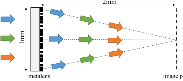
Figure 3-1: Achromatic metalens structure. Different colors stand for different wave-lengths, they all focus on the same focal spot.
Table 3.1: Achromatic metalens parameters lens size 1 mm focal length 2 mm NA 0.24 wavelength 6-8 µm meta-atom period 4 µm wavelength spacing 0.1 µm computation time 30 mins
of the meta-atoms design. The benefit of this definition is that it only requires the computation of intensity at a single position. Compared to other FOMs which use various parameters like focusing efficiency or Strehl ratio to define the focusing quality, it reduces computational complexity while does not sacrifice the optimization quality. Also note that only the intensity on the axis is required, which means that angular symmetry not only applies to the metalens’ phase profile, but also applies to the diffraction integral. Therefore, it can be further simplified into following:
e U (P ) = −i λ ∑ N (R) 1 2(cosθ0+ cosθ)Uf0(N (R))ΦN (R) 1 re ikr2πRΛ (3.2)
Here, the summation only applies to the meta-atoms on a single line along the radius since all the contributions from meta-atoms on the concentric circles are the same.
quickly after only a few times. Here the results after the second iteration are presented which should be close to the optimum results achieved by this method. The compu-tation time of optimization for one iteration takes 30 mins on a personal computer at the current size of meta-atom library.
The 1D intensity profiles along the dashed line on Fig. 3-1 and the 2D profiles at image plane with various wavelengths are shown at Fig. 3-3. The correspond-ing efficiency, full-width-at-half-maximum (FWHM) and Strehl ratio with continuous wavelengths are shown at Fig. 3-4. Here, the efficiency is defined as the transmitted power surrounding the focal spot in the 5 FWHM range divided by the total power that passes through the metalens. Its loss is contributed from both the none-unity transmittance of the meta-atoms and background noise at image plane. Strehl ratio is defined as peak intensity of the metalens divided by the highest achievable intensity at this wavelength with hyperbolic phase with their power in the 5 FWHM range normalized. From these plots, it can be seen that the designed metalens exhibits superior achromatic focusing ability in the whole wavelengths range with little de-viation among different wavelengths. The continuous efficiency, FWHM and Strehl ratio plots without oscillations mean our sampling of wavelengths (0.1 µm) is already accurate enough to produce continuous achromatic focusing.
Here, an image taken from Oleksiy Maksymenko [31] is used to demonstrate achro-matic lens’ imaging capability. The image shown at Fig. 3-5 is placed in front of both a conventional lens optimized at center wavelength of 7 µm and the broadband met-alens optimized in the range of 6− 8 µm. The captured images at focal plane are simulated with lights of different frequencies. Fig. 3-6 (a)-(c) show simulated images from monochromatic lens, it has perfect focusing at the center designed wavelength of 7 µm but the quality decays rapidly at other wavelengths. On the other side, Fig. 3-6 (d)-(f) show simulated images of the achromatic lens, they clearly exhibit satisfying focusing quality at the entail wavelengths range.
The phase profiles at some wavelengths are shown at Fig. 3-7 where the red lines stand for the ideal hyperbolic phase profiles as comparison. They deviate from hyper-bolic phase to produce achromatic behavior while maintain relatively high focusing
Figure 3-2: FOM with increasing iteration times. The initial FOM is normalized to be unity. It converges quickly after a few iteration times.
Figure 3-3: (a)-(c) Normalized 1D intensity profiles at image plane with incident wavelength of (a) 6 µm, (b) 7 µm and (c) 8 µm. Blue lines show results from achromatic metalens, red lines correspond to results from lens optimized at certain wavelength with hyperbolic phase profile. (d)-(f) Normalized 2D intensity profiles at image plane with incident wavelength of (d) 6 µm, (e) 7 µm and (f) 8 µm.
Figure 3-4: Image quality characterization of achromatic metalens. (a) FWHM plot with wavelengths. Blue dots come from achromatic metalens, red dots are acquired from lens optimized at certain wavelength as comparison. (b) Efficiency plot with wavelengths. (c) Strehl ratio plot with wavelengths. The red dashed line corresponds to diffraction limit with Strehl ratio = 0.8.
Figure 3-6: Comparison of image quality captured by lens optimized at center wave-length and the designed achromatic metalens. (a)-(c) Images from monochromatic lens at wavelength of (a) 6 µm, (b) 7 µm and (c) 8 µm. (d)-(f) Images from achromatic metalens at wavelength of (d) 6 µm, (e) 7 µm and (f) 8 µm.
quality. Note also that the phase profiles of different wavelengths resemble every other to achieve continuous achromatic focusing. This benefits from the plenty of choic-es from meta-atoms’ dispersion behavior of the library which brings another critical DOF. Fig. 3-8 shows typical dispersion behaviors of some selected meta-atoms, the desired resonant behavior in the selected wavelength range helps compensate disper-sion along the propagation length. This brings one major advantage of metalens over diffractive lens design.[28] In that design, the phase modification is acquired from the difference of the optical path length in the grooves. This means, apart from the slight dispersion of the refractive index (RI) of the groove material, the only major disper-sion comes from the propagation term with the 1/λ characteristics. This restricts the degree of freedom and is far less enough to provide dispersion behavior complexity. On the other side, meta-atoms show resonant behavior, they can be designed to have large dispersion in the interested wavelengths range.
Figure 3-7: Phase profiles of achromatic metalens at wavelength of (a) 6 µm, (b) 7 µm and (c) 8 µm. Red lines show optimum hyperbolic phase at the specific wavelength. Blue lines show phase profiles of achromatic metalens.
Figure 3-8: Case examples of meta-atoms’ dispersion behavior for achromatic metal-ens. Selected wavelengths range is highly dispersive to partially compensate chromatic propagational phase differences.
Figure 3-9: (a) Efficiency and (b) Strehl ratio of designed achromatic metalens (blue curve) and diffractive lens (red curve).
3-9 shows the efficiency and Strehl ratio at different NAs with the results of the diffractive lens as a comparison. While efficiency decreases at larger NAs due to the abrupt phase change at the metalens edge which is common for all image devices design, it still shows relatively satisfying values at NA as large as 0.6.
Further improvements can be made by expanding the meta-atoms library. This way, meta-atoms with more suitable dispersion behavior and higher transmittance can be adopted to improve the focusing quality.
3.2
WFOV metalens
WFOV imaging capability is desired for a wide range of applications including high performance detection, beam projection, augmented reality, etc.[32][33][34][22] Op-tical systems showing WFOV feature were invented long ago with the structure of ‘fisheye lenses’. Complexed optical lenses are assembled along the optical path to compensate aberrations from large incident angles.[35][36][37] However, their bulky feature increases size, weight and cost of the product which limits their usage in many fields. Therefore, substituting ‘fisheye lenses’ with a single piece of metalens would be helpful.
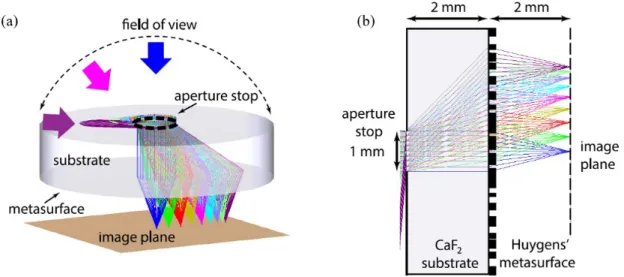
The basic concept of WFOV metalens is illustrated at Fig. 3-10. The metalens structure in Ref. [2] is adopted here. The special characteristic is that the metalens
Figure 3-10: Schematic illustration of WFOV metalens design. (a) 3D-view. (b) Side view. Reprinted from [2].
is attached to a substrate with certain thickness and an aperture is placed at the opposite side of the substrate. Light of different AOIs pass through the aperture, refracted by the substrate and focus on different areas of the metalens. Metalens’ structure parameters are listed at Tab. 3.2. The substrate is made up of CaF2 with
RI of 1.45 at λ = 5 µm. With AOIs covering the whole 0−90oover the half-sphere, the
angles inside the substrate are actually 0− 44o. Therefore, beams cover the metalens area that has the radius around the thickness of the substrate. This way, beams with different AOIs are more or less separated and different areas on the metalens can be used to optimize different AOIs.[38] However, for small beam angles, they have large superimposing area on the metalens, so optimization is required to have satisfying and equal focusing quality among these different angles. This structure is superior than the normal structure of thin substrate without aperture in that it provides beam separation and doesn’t require the whole metalens’ surface to optimize all the AOIs simultaneously.
The optimum phase profile of this metalens structure is first derived. Consider the illustration at Fig. 3-11 (a). Two beams parallel to each other separated by ∆s pass through the metalens and focus at the same spot on the image plane. The phase of the metalens is ϕ(s) which is radius dependent. These two beams experience
Table 3.2: WFOV metalens parameters
lens size 5 mm focal length 2 mm aperture diameter 1 mm substrate thickness 2 mm NA 0.24 wavelength 5 µm meta-atom period 4 µm
different phase change ∆ϕ on the metalens to compensate their propagational optical path length differences. Therefore, ∆s and ∆ϕ satisfy the following relationship:
∆s· nsinθ + ∆ϕ λ 2π + ( ∂ ∂s √ (s− d)2+ f2)∆s = 0 (3.3)
Here, n is the RI of the substrate and λ is the operational wavelength. Integration reveals the phase profile of the metalens:
ϕ(s) = ∫ s 0 −( ns √ s2+ L2 + s− d √ f2+ (s− d)2)ds( 2π λ ) (3.4)
It needs to be mentioned that d, the focal spot position, is actually a function of s which is determined by AOI. This is different from achromatic metalens where only the phase profile needs to be determined, here the focal spot position changes with AOI. The following will show that there also exists an optimum focal spot position -AOI relationship under this structure that maximizes focusing quality. Fig. 3-11 (b) illustrates the structure with two light beams of slightly different AOIs. They share the same area on the metalens but focus at slightly different positions denoted by ∆d. Like before, the blue beam satisfies:
∆s· nsinθ + ∆ϕ λ 2π + ( ∂ ∂s √ (s− d)2+ f2 )∆s = 0 (3.5)
The orange beam is similar by changing θ with θ + ∆θ and d with d + ∆d. The equation is as follow: ∆s· nsin(θ + ∆θ) + ∆ϕ λ 2π + ( ∂ ∂s √ (s− (d + ∆d))2+ f2 )∆s = 0 (3.6)
Note that they share the same metalens area, so ∆ϕ is the same. Comparing these two equations, the relationship of θ and d can be obtained:
ncosθ∆θ + ∂ ∂d(
s− d
√
(s− d)2+ f2)∆d = 0 (3.7)
Finally, angle inside the substrate can be related with AOI α using sinα = nsinθ (Snell’s Law) and the final differential relationship can be obtained:
∆d = [(√ Lsinα
n2− sin2α − d)
2+ f2 ]32(cosα
f2 )∆α (3.8)
Apart from this theoretical analysis, these relations can also be obtained empir-ically by the aforementioned direct search algorithm as a comparison. The process is similar to that of achromatic metalens and the same meta-atoms library is used. Now the FOM is defined as:
F OM =∑
i
IAOI(i) (3.9)
Here, IAOI(i) is the focal spot intensity of different chosen AOIs. Since the focal
spot position is not specifically assumed in the simulation, for every AOI, it searches through a wide range of positions on the image plane that has size comparable to the metalens and pick up the highest intensity point as the focal spot. This means it has a higher computational load than broadband metalens, but it serves as a proof of the focal spot - AOI relationship derived before theoretically.
Here, λ = 5 µm is used as an illustration, but this method is versatile for any monochromatic lens. Fig. 3-12 shows focal spot position and phase profile from both theoretical analysis and simulation. The excellent agreement between them serves as a verification of the effectiveness of these two approaches.
Fig. 3-13 and Fig. 3-14 show one-dimensional and the central part two-dimensional focal spot quality of different AOIs respectively. Note that in Fig. 3-14 the central position of x axis is the theoretically estimated focal spot position. The total x axis range is 30 µm, the deviation of the actual focal spot position from the above
theo-Figure 3-11: Schematic illustrations of focusing process. (a) Two parallel beams focus at the same position. (b) Beams with different AOIs share same area of metalens but focus at different positions.
Figure 3-12: Comparison of (a) focal spot position and (b) metalens’ phase profile from theoretical analysis (red lines) and direct search algorithm simulation (blue lines). In figure (a), the two lines are so close to each other that it’s difficult to distinguish them.
retical analysis is less than 5 µm whereas FWHM is around 10 µm. This means the theoretical analysis of focal spot position is highly accurate. Fig. 3-15 shows efficien-cy and Strehl ratio plot with AOIs. All these are derived using the equations in the theoretical analysis and areas larger than Fig. 3-14 are used to correctly account for background noise. The intensity profiles are computed using Kirchhoff diffraction in-tegral. It clearly exhibits high focusing quality over the entail and continuous 0− 90o
range which meets the WFOV metalens requirement.
Finally, analyses are made showing the impact of different design parameters. The previous design has focal length f = 2 mm, this corresponds to a NA of 0.24. There are two ways of modifying NA, whether by changing focal length or by changing aperture size. Their effects on average efficiency and Strehl ratio are shown at Fig. 3-16 (a) (b). Shorter focal length requires more abrupt change of phases which influences focusing quality. On the other side, by using larger aperture size, superimposed area with different AOIs gets larger which also influences focusing quality. Another parameter that is free to change is the substrate thickness, its influence on average efficiency and Strehl ratio is shown at Fig. 3-16 (c). By increasing substrate thickness, beams of different AOIs are more separated, their superimposed areas are reduced,
Figure 3-13: Normalized one-dimensional field intensity on image plane along the line parallel to incident light beam plane with AOI of (a) 0o, (b) 30o, (c) 60o and (d)
90o. Red lines correspond to lens with phase optimized at the certain AOI. Blue lines correspond to intensity profile from designed WFOV metalens.
Figure 3-14: Normalized two-dimensional field intensity on image plane with AOI of (a) 0o, (b) 30o, (c) 60o and (d) 90o.
Figure 3-15: Metalens (a) focusing efficiency and (b) Strehl ratio with increasing AOIs. The red dashed line corresponds to diffraction limit with Strehl ratio = 0.8. It exhibits high focusing quality up to 90o incidence.
Figure 3-16: (a)(b) Effects of NA on average efficiency and Strehl ratio among the WFOV by changing (a) focal length and (b) aperture size. (c) Effects of substrate thickness on average efficiency and Strehl ratio.
so better focusing quality can be achieved. However, thicker substrate is not always desirable since it will increase the size of the device. Also, propagation length inside the substrate gets larger, absorption of the substrate can be significant when it’s too thick. A trade off can be seen from all these results, the image quality can be compromised to concentrate more light or produce smaller device. Therefore, the optimum structure parameters depend on specific design requirement.
3.3
Achromatic and WFOV metalens
With the achromatic metalens design and WFOV metalens design mentioned above, it is straightforward to think about method that can combine these two valuable features together. While many researches focus on one of these two features[39][40][41][42], it is not common to find designs that achieve both of them simultaneously. However, it takes no much effort utilizing the two approaches mentioned before together to create metalens with both features. In this way, all kinds of aberrations can be corrected with a single piece of metalens. This vastly decreases size of device and revolutionizes the whole imaging sphere.
Similar to the previous metalens design, two properties need to be determined -the focal spot position and phase profile. Here we consider focal spot position first. It’s dependence with AOIs has already been derived at former section, it’s listed here again:
Table 3.3: Achromatic and WFOV metalens parameters lens size 5 mm focal length 2 mm aperture diameter 1 mm substrate thickness 2 mm NA 0.24 wavelength 5− 7.5 µm meta-atom period 4 µm computation time 3 hours
∆d = [(√ Lsinα
n2− sin2α − d)
2+ f2 ]32(cosα
f2 )∆α (3.10)
The only term that depends on wavelengths is the refractive index n. Since the substrate material BaF2 used here has little dispersion behavior in the interested
wavelengths range, focal spot has only weak dependence on wavelengths.
A metalens with broadband focusing in the 5− 7.5 µm wavelengths range and WFOV covering the whole 0 − 180o is demonstrated here as a case example. Its
parameters are listed at Tab. 3.3. For simplification, n is taken to be the value at 6µm wavelength in the direct search algorithm. Optimum focal spot position is derived using the above equation at 6 µm wavelength but is applied to the whole broadband range. This only brings a maximum of 7 µm focal spot position variance considering the small dispersion of RI.
The next focus is the phase profile of metalens. Compared to the WFOV metalens, only difference here is the wavelength dependence of phase profile. One way of solving this is to use dispersion engineering. In this method, meta-atoms’ dispersion behavior is engineered to make the best effort to fulfill the phase requirement at different wavelengths. However, it’s extremely difficult to find the optimum meta-atoms shape giving the desired dispersion behavior. Therefore, direct search algorithm is applied here again to pick optimum meta-atom at certain metalens position from the same meta-atoms library. One way of defining FOM is at following:
F OM =∑
i,j
cλ(i),α(j)· Iλ(i),α(j) (3.11)
that depend on these parameters. This is used to minimize variation of focusing quality among different parameters. However, it makes the algorithm complicated since weights need to be determined empirically and they also depend on specific structure parameters. Therefore, a new FOM here is defined at following:
F OM =∑
i,j
Iλ(i),α(j)− κ · S2{Iλ(i),α(j)} (3.12)
The difference is at the second term where S2 is the variance of intensities and
κ = 0.5 is a coefficient. This way, when changing structure parameters, only proper
value of κ needs to be obtained empirically.
Combining the direct search algorithm and WFOV focal spot theoretical analy-sis, the metalens design is conducted at a wavelength sampling of 0.5 µm and AOI sampling of 10o. The computation time is 3 hours using cloud service with 64 CPU
cores. A even better result can be obtained with finer sample spacing at the expense of computation time. The intensity profiles at some of the wavelengths and AOIs are shown at Fig. 3-17. The efficiency and Strehl ratio at the sampling wavelengths and AOIs are shown at Fig. 3-18. With the proper design of phase profile, it shows almost comparable imaging quality with mere achromatic metalens. This achromatic and WFOV metalens design exhibits high efficiency at the whole wavelengths and AOIs range.
Figure 3-17: (a)-(c) Intensity profiles at AOI = 0o and (a) λ = 5 µm, (b) λ = 6 µm, (c) λ = 7 µm. (d)-(f) Intensity profiles at AOI = 90oand (d) λ = 5 µm, (e) λ = 6 µm,
(f) λ = 7 µm.
Chapter 4
Conclusions and outlook
Metalens designs are presented here to solve chromatic and angle-dependent aberra-tions faced by conventional lenses. The first illustration is an achromatic metalens that exhibits high focusing quality over the entail 6− 8 µm wavelengths range. Di-rect search algorithm is used to obtain optimum phase profile while the meta-atoms are chosen from a large library containing meta-atoms with diverse dispersion be-havior. After this, a WFOV metalens with simple configuration is designed that has unprecedented diffraction-limited FOV of the whole 0− 180o. The optimum phase profile and focal spot position is derived theoretically and agrees well with the design from direct search algorithm. Finally, these two designs are combined together to produce metalens that achieve achromatic and WFOV features simultaneously. The focal spot position is predicted by the theoretical analysis whereas optimum phase profile is acquired using direct search algorithm. The designed metalens shows broad-band focusing in the whole 5− 7.5 µm wavelengths range and 0 − 180o FOV with high imaging quality. It needs to mention that this approach is versatile, it can be adapted to other wavelengths range by simply modifying meta-atoms library.
Further improvements can be made though, to achieve even better performance. In the achromatic and WFOV metalens design, the sampling of wavelengths is set to be 0.5 µm which is limited by the computation time and memory at this time. How-ever, simulation shows that efficiencies begin to drop at the intermediate wavelength between the neighboring samples. This means a finer sampling of wavelengths is
needed. Further improvements of algorithm can be made to reduce computation time and memory requirement. Another issue is the wavelength dependence of substrate RI. This causes slight change of focal spot position with wavelengths. To solve this issue, substrate dispersion can be engineered whether by using materials with smaller dispersion or combining two substrates with opposite dispersion behavior together to compensate their effect. Another thing that can be done is to expand the meta-atoms library. By doing this, more meta-atom designs can be chosen by the direct search algorithm and even better achromatic performance can be achieved. In the achro-matic and WFOV metalens design, the negative variance term is added in the FOM to help minimize variation of focusing quality among different AOIs and wavelengths. As mentioned before, the variation can be further decreased by adding weights before intensities of different conditions in the definition of FOM at the expense of increased complexity. Finally, the NA and substrate thickness dependence of the quality have already been presented, they can be used to optimize structure parameters such as metalens size, substrate thickness and focal length.
Despite these potential improvements, the metalens architecture already shows high focusing quality with simple structure. It can be integrated in the next generation systems for various applications including imaging, sensing, projections, augmented reality, etc. and vastly enhances devices’ performance.
Bibliography
[1] Xi-hua Zhong. Modern fundamentals of optics, 2003.
[2] Mikhail Y Shalaginov, Sensong An, Fan Yang, Peter Su, Dominika Lyzwa, A-nuradha M Agarwal, Hualiang Zhang, Juejun Hu, and Tian Gu. Single-element diffraction-limited fisheye metalens. Nano Letters, 20(10):7429–7437, 2020. [3] Nanfang Yu, Patrice Genevet, Mikhail A Kats, Francesco Aieta, Jean-Philippe
Tetienne, Federico Capasso, and Zeno Gaburro. Light propagation with phase discontinuities: generalized laws of reflection and refraction. science,
334(6054):333–337, 2011.
[4] Federico Capasso. The future and promise of flat optics: a personal perspective.
Nanophotonics, 7(6):953–957, 2018.
[5] Seyedeh Mahsa Kamali, Ehsan Arbabi, Amir Arbabi, and Andrei Faraon. A review of dielectric optical metasurfaces for wavefront control. Nanophotonics, 7(6):1041–1068, 2018.
[6] Hou-Tong Chen, Antoinette J Taylor, and Nanfang Yu. A review of metasurfaces: physics and applications. Reports on progress in physics, 79(7):076401, 2016. [7] Mohammadreza Khorasaninejad and Federico Capasso. Metalenses: Versatile
multifunctional photonic components. Science, 358(6367), 2017.
[8] Ramon Paniagua-Dominguez, Ye Feng Yu, Egor Khaidarov, Sumin Choi, Victor Leong, Reuben M Bakker, Xinan Liang, Yuan Hsing Fu, Vytautas Valuckas, Leonid A Krivitsky, et al. A metalens with a near-unity numerical aperture.
Nano letters, 18(3):2124–2132, 2018.
[9] VV Kotlyar, AG Nalimov, SS Stafeev, Changyu Hu, Liam OąŕFaolain, MV Kotl-yar, Desmond Gibson, and Shigeng Song. Thin high numerical aperture metalens.
Optics Express, 25(7):8158–8167, 2017.
[10] Haowen Liang, Qiaoling Lin, Xiangsheng Xie, Qian Sun, Yin Wang, Lidan Zhou, Lin Liu, Xiangyang Yu, Jianying Zhou, Thomas F Krauss, et al. Ultrahigh numerical aperture metalens at visible wavelengths. Nano letters, 18(7):4460– 4466, 2018.
[11] Bo Han Chen, Pin Chieh Wu, Vin-Cent Su, Yi-Chieh Lai, Cheng Hung Chu, I Chen Lee, Jia-Wern Chen, Yu Han Chen, Yung-Chiang Lan, Chieh-Hsiung Kuan, et al. Gan metalens for pixel-level full-color routing at visible light. Nano
letters, 17(10):6345–6352, 2017.
[12] Amir Arbabi, Yu Horie, Mahmood Bagheri, and Andrei Faraon. Dielectric meta-surfaces for complete control of phase and polarization with subwavelength spa-tial resolution and high transmission. Nature nanotechnology, 10(11):937–943, 2015.
[13] Max Born and Emil Wolf. Principles of optics: electromagnetic theory of
propa-gation, interference and diffraction of light. Elsevier, 2013.
[14] Jong-Ung Lee and Seung-Moon Yu. Analytic design procedure of three-mirror telescope corrected for spherical aberration, coma, astigmatism, and petzval field curvature. Journal of the Optical Society of Korea, 13(2):184–192, 2009.
[15] Michael J Kidger. Fundamental optical design. SPIE Bellingham, 2001.
[16] Wei Ting Chen, Alexander Y Zhu, Vyshakh Sanjeev, Mohammadreza Khorasa-ninejad, Zhujun Shi, Eric Lee, and Federico Capasso. A broadband achromat-ic metalens for focusing and imaging in the visible. Nature nanotechnology,
13(3):220–226, 2018.
[17] Sajan Shrestha, Adam C Overvig, Ming Lu, Aaron Stein, and Nanfang Yu. Broadband achromatic dielectric metalenses. Light: Science & Applications,
7(1):1–11, 2018.
[18] Fatih Balli, M Sultan, Sarah K Lami, and Jeffrey T Hastings. A hybrid achro-matic metalens. Nature communications, 11(1):1–8, 2020.
[19] Haejun Chung and Owen D Miller. High-na achromatic metalenses by inverse design. Optics Express, 28(5):6945–6965, 2020.
[20] Francesco Aieta, Patrice Genevet, Mikhail Kats, and Federico Capasso. Aber-rations of flat lenses and aplanatic metasurfaces. Optics express, 21(25):31530– 31539, 2013.
[21] Amir Arbabi, Ehsan Arbabi, Seyedeh Mahsa Kamali, Yu Horie, Seunghoon Han, and Andrei Faraon. Miniature optical planar camera based on a wide-angle metasurface doublet corrected for monochromatic aberrations. Nature
commu-nications, 7(1):1–9, 2016.
[22] Augusto Martins, Kezheng Li, Juntao Li, Haowen Liang, Donato Conteduca, Ben-Hur V Borges, Thomas F Krauss, and Emiliano R Martins. On metalenses with arbitrarily wide field of view. ACS Photonics, 7(8):2073–2079, 2020.
[23] Andrey B Evlyukhin, Carsten Reinhardt, and Boris N Chichkov. Multipole light scattering by nonspherical nanoparticles in the discrete dipole approximation.
Physical Review B, 84(23):235429, 2011.
[24] AI Kuznetsov, AE Miroshnichenko, YH Fu, J Zhang, and B LukąŕYanchuk. Magnetic light sci. Rep, 2:492, 2012.
[25] Li Zhang, Jun Ding, Hanyu Zheng, Sensong An, Hongtao Lin, Bowen Zheng, Qingyang Du, Gufan Yin, Jerome Michon, Yifei Zhang, et al. Ultra-thin high-efficiency mid-infrared transmissive huygens meta-optics. Nature
communica-tions, 9(1):1–9, 2018.
[26] Peng Wang, Jose A Dominguez-Caballero, Daniel J Friedman, and Rajesh Menon. A new class of multi-bandgap high-efficiency photovoltaics enabled by broadband diffractive optics. Progress in Photovoltaics: Research and
Applica-tions, 23(9):1073–1079, 2015.
[27] Peng Wang and Rajesh Menon. Optical microlithography on oblique and multi-plane surfaces using diffractive phase masks. Journal of Micro/Nanolithography,
MEMS, and MOEMS, 14(2):023507, 2015.
[28] Peng Wang, Nabil Mohammad, and Rajesh Menon. Chromatic-aberration-corrected diffractive lenses for ultra-broadband focusing. Scientific reports,
6:21545, 2016.
[29] Antonin Miks and Jiri Novak. Superachromatic air-spaced triplet. Applied optics, 53(29):6930–6937, 2014.
[30] Yi-Chin Fang, Chen-Mu Tsai, John MacDonald, and Yang-Chieh Pai. Eliminat-ing chromatic aberration in gauss-type lens design usEliminat-ing a novel genetic algorith-m. Applied Optics, 46(13):2401–2410, 2007.
[31] Oleksiy Maksymenko. Getty images.
[32] Yibo Ni, Sai Chen, Yujie Wang, Qiaofeng Tan, Shumin Xiao, and Yuanmu Yang. Metasurface for structured light projection over 120ą field of view. Nano Letters, 20(9):6719–6724, 2020.
[33] Gun-Yeal Lee, Jong-Young Hong, SoonHyoung Hwang, Seokil Moon, Hyeokjung Kang, Sohee Jeon, Hwi Kim, Jun-Ho Jeong, and Byoungho Lee. Metasurface eyepiece for augmented reality. Nature communications, 9(1):1–10, 2018.
[34] Yanjun Chen, Zhe Guo, Ke Liu, Lihui Liu, and Yanqiu Li. Quantitative anal-ysis of wide field-of-view and broadband quarter-wave plate based on metasur-face. In 2017 International Conference on Optical Instruments and Technology:
Micro/Nano Photonics: Materials and Devices, volume 10622, page 106220G.
[35] Hyungtae Kim, Jaehoon Jung, and Joonki Paik. Fisheye lens camera based surveillance system for wide field of view monitoring. Optik, 127(14):5636–5646, 2016.
[36] Gyeongil Kweon and Milton Laikin. Fisheye lens, November 22 2011. US Patent 8,064,149.
[37] Tuan Ho and Madhukar Budagavi. Dual-fisheye lens stitching for 360-degree imaging. In 2017 IEEE International Conference on Acoustics, Speech and Signal
Processing (ICASSP), pages 2172–2176. IEEE, 2017.
[38] Dale A Buralli and G Michael Morris. Design of a wide field diffractive landscape lens. Applied optics, 28(18):3950–3959, 1989.
[39] Ren Jie Lin, Vin-Cent Su, Shuming Wang, Mu Ku Chen, Tsung Lin Chung, Yu Han Chen, Hsin Yu Kuo, Jia-Wern Chen, Ji Chen, Yi-Teng Huang, et al. Achromatic metalens array for full-colour light-field imaging. Nature
nanotech-nology, 14(3):227–231, 2019.
[40] Mohammadreza Khorasaninejad, Zhujun Shi, Alexander Y Zhu, Wei-Ting Chen, Vyshakh Sanjeev, Aun Zaidi, and Federico Capasso. Achromatic metalens over 60 nm bandwidth in the visible and metalens with reverse chromatic dispersion.
Nano letters, 17(3):1819–1824, 2017.
[41] Jacob Engelberg, Chen Zhou, Noa Mazurski, Jonathan Bar-David, Anders Kris-tensen, and Uriel Levy. Near-ir wide-field-of-view huygens metalens for outdoor imaging applications. Nanophotonics, 9(2):361–370, 2020.
[42] Yinghui Guo, Xiaoliang Ma, Mingbo Pu, Xiong Li, Zeyu Zhao, and Xiangang Luo. High-efficiency and wide-angle beam steering based on catenary optical fields in ultrathin metalens. Advanced Optical Materials, 6(19):1800592, 2018.

![Figure 2-3: Illustration of Kirchhoff diffraction integral. Reprinted from [1].](https://thumb-eu.123doks.com/thumbv2/123doknet/13831739.443332/22.892.266.664.152.455/figure-illustration-kirchhoff-diffraction-integral-reprinted.webp)

![Figure 3-5: Sample image placed in front of metalens. Image taken by Ref. [31]](https://thumb-eu.123doks.com/thumbv2/123doknet/13831739.443332/29.892.138.780.529.1010/figure-sample-image-placed-metalens-image-taken-ref.webp)