Publisher’s version / Version de l'éditeur:
Journal of Thermal Insulation and Building Envelopes, 19, January 1, pp.
244-275, 1996-01-01
READ THESE TERMS AND CONDITIONS CAREFULLY BEFORE USING THIS WEBSITE. https://nrc-publications.canada.ca/eng/copyright
Vous avez des questions? Nous pouvons vous aider. Pour communiquer directement avec un auteur, consultez la première page de la revue dans laquelle son article a été publié afin de trouver ses coordonnées. Si vous n’arrivez pas à les repérer, communiquez avec nous à PublicationsArchive-ArchivesPublications@nrc-cnrc.gc.ca.
Questions? Contact the NRC Publications Archive team at
PublicationsArchive-ArchivesPublications@nrc-cnrc.gc.ca. If you wish to email the authors directly, please see the first page of the publication for their contact information.
NRC Publications Archive
Archives des publications du CNRC
This publication could be one of several versions: author’s original, accepted manuscript or the publisher’s version. / La version de cette publication peut être l’une des suivantes : la version prépublication de l’auteur, la version acceptée du manuscrit ou la version de l’éditeur.
Access and use of this website and the material on it are subject to the Terms and Conditions set forth at
Performance linkage approach: environmental control of buildings.
Part I: construction today
Lstiburek, J. W.; Bomberg, M. T.
https://publications-cnrc.canada.ca/fra/droits
L’accès à ce site Web et l’utilisation de son contenu sont assujettis aux conditions présentées dans le site
LISEZ CES CONDITIONS ATTENTIVEMENT AVANT D’UTILISER CE SITE WEB.
NRC Publications Record / Notice d'Archives des publications de CNRC:
https://nrc-publications.canada.ca/eng/view/object/?id=8c066994-dd07-4da4-ac20-4dad8ec5a681 https://publications-cnrc.canada.ca/fra/voir/objet/?id=8c066994-dd07-4da4-ac20-4dad8ec5a681http://www.nrc-cnrc.gc.ca/irc
Pe rform a nc e link a ge a pproa c h: e nvironm e nt a l c ont rol of buildings.
Pa rt 1 : c onst ruc t ion t oda y
N R C C - 3 8 8 4 3
L s t i b u r e k , J . W . ; B o m b e r g , M . T .
J a n u a r y 1 9 9 6
A version of this document is published in / Une version de ce document se trouve dans:
Journal of Thermal Insulation and Building Envelopes,
19, (1), January, pp.
244-275, January 01, 1996
The material in this document is covered by the provisions of the Copyright Act, by Canadian laws, policies, regulations and international agreements. Such provisions serve to identify the information source and, in specific instances, to prohibit reproduction of materials without written permission. For more information visit http://laws.justice.gc.ca/en/showtdm/cs/C-42
Les renseignements dans ce document sont protégés par la Loi sur le droit d'auteur, par les lois, les politiques et les règlements du Canada et des accords internationaux. Ces dispositions permettent d'identifier la source de l'information et, dans certains cas, d'interdire la copie de documents sans permission écrite. Pour obtenir de plus amples renseignements : http://lois.justice.gc.ca/fr/showtdm/cs/C-42
/Vf(CC-388cf3
Performance Linkage Approach:
Environmental Control of Buildings
Part I: Construction Today
JOSEPH W. LSTIBUREK
Building Science Corporation Chestnut Hill, MA 02167
MARK
T.
BOMBERGNational Research Council Canada Ottawa, Ontario, KIA OR6
INTRODUCTION
T
HIS STATE-OF-THE art paper reviews the area of environmental control of buildings, outlines some research findings, and analyzes different aspects of the design process with a view to creating a comprehensive stage for the introduction of new ideas.This paper underlines shortcomings in the current design process and highlights areas where the current design and evaluation processes must be improved to enhance innovation in the construction industry_ Part II of this work (to be published in JTIBE) proposes improvements based on a holistic approach to the environmental control of buildings.
RECENT CHANGES IN CONSTRUCTION
,1
In the past, building envelopes were leaky and natural ventilation was relied upon to bring fresh air into buildings. Until the energy crisis of the late 19705, energy was inexpensive. Our approach to environmental control of buildings has changed since that time.
Increased tightness of building envelopes, controlled ventilation, and air-conditioning systems are relatively recent additions to building technology. Recent trends to thicker thermal insulation in cold climates caused the
pri-244 J. THERMAL 'NSUL. AND BLDG. ENVS. Volume 19-January 1996 1065-2744/96/030244-35 510.0010
Performance Linkage Approach: Environmental Control of Buildings, Part I 245
mary exhausr device, rhe chimney flue, ro be used less frequenrly'. The rrend toward using electric heating, heat pumps, and power vented sealed com-bustion furnaces has further eroded the role of a traditional active chimney. Chimney flues acted as exhaust fans which extracted great quantities of air from the conditioned space, reducing the moisture load acting on the build-ing envelope. Less efficient chimney flues increased the indoor air humidity resulting in more frequent condensation on surfaces of windows or thermal bridges. More recently, rhe significance of rhis issue was reinforced by in-creased epidemiological evidence that links respiratory diseases to dampness (Robinson, 1992).
Indoor Environment
Building enclosures have become signiflcanrly tighter, reducing the ex-change of air between the indoor and outdoor environments.
The lower the air exchange, the less effective the dilution of pollutants in the indoor space. New consumer products increased the variety of pollutants in the indoor air. The reduced dilution caused concentrations of these pollu-tants to increase even further. These pollupollu-tants include moisture (from peo-ple and appliances), formaldehyde (from particle board and furnishings), volatile organic compounds (from carpets, paints, cleaners, and adhesives), radon (from basements, crawl spaces, water supplies) and carbon dioxide (from people).
It is important to recognize that relying on random leakage openings and the effects of wind and stack effects to provide the required air change does not ensure dilution when most needed. In small buildings, the variations in building airtightness are enormous. Leaky buildings are often two to three times leakier than tight buildings. Compounding these concerns is the diffi-culty in predicting how tight a building will be when built using contional construction practices. In effect, for health reasons, mechanical ven-tilation is a requirement in all buildings, tall or small.
In sonte residences, the installation and use of indoQr spas, hot tubs, and central humidifIers made moi$ture control more difficult. In commercial and institutional buildings, the installation of pressurized and humidified com-puter rooms and special use areas such as health clubs or copying/duplication rooms created additional environments that are hostile to humans.
These changes in construction 'processes introduced new considerations for materials.
'In the extreme, reducing the chimney's abilityエセ exhaust products of combustion may lead to spillage of combustion products, backdrafting of furnaces and fireplaces, and associated health and safety problems.
246 JOSEPHW. lST1BUREK AND MARKT. BOMBERG
1
Material ConsiderationsAny rna terial must be assessed in the context of a system. What is the
function of the material? Can the material perform the function? What is the
risk to the occupants, the building, and the environment? Extending this ar-gument further; there are no truly benign materials, and nothing is com-pletely risk free, However, risk can be managed. For example, a toxic material can provide significant benefIts and pose little risk when used prop-erly. The use of some damp-proofings on the exterior of a concrete or pre-served wood foundation illustrates this point. An inherently toxic material provides substantial benefits to the system (moisture control) and does not pose a high risk to the occupants.
Concerns have been raised on howmany synthetic agents impact the
in-door environment. It has been voiced that "natural" or "green" materials should be used. However, many "natural" materials contain volatile organic compounds, are potent irritants, and pose hazards to health. Allergic reac-tions to the odors emanating from "cedar" closets and chests are common. As well, radium and radon are natural materials. Yet, nobody would suggest that these two "natural" materials be used in construction, though radon gas could be used in sealed glazing systems in place of argon, and radium could be used on thermostat dials to make them easy to read at night.
The risk to occupants is low if a particular agent remains in the building product and does not affect people through respiration and physical contact. In general, building materials which do not off-gas are preferable to those that do. Products which off-gas a little are preferable to those which off-gas a great deal. Less toxic alternatives should be used in place of more toxic marerials. The principle of product substitution should be employed wher-ever possible.
For volatile organic compounds (VOC), the decay of their emission rate must be considered. For example, most interior paints contain signiflcant quautities of VOC (solvents). They off-gas or evaporate very rapidly and leave behind a relatively "benign" surface. After some period, these materials pose little risk to most occupants over the rest of the service life. However, they may pose a real "risk" to the painters as an occupational hazard.
Superimposed over all of the specific concerns about material and product use on the interior environment of a building and the occupants, are the con-cerns relating to the local and global environment. Is it more appropriate to use a recycled mat'erial in place of a new material? Is the new material or product manufactured in anon disruptive or least-disruptive mannet tothe environment? How much energy was used to make it?
These are all valid and'important concerns. Sometimes, however, in pursu-ing one of the detailed concerns, we lose the bigger picture. For instance, a
Performance Linkage Approach: Environmental Control of Buildings, Part I 247
large embedded energy content is often voiced against the use offoam
plas-tic insulations. Franklin Associates (1991) calculated energy consumption
through each stage of a product's life cycle. This calculation included the
en-ergy input involved in acquisition of raw materials, materials manufacure, material waste, product and by-products manufacture, production waste, cost of transportation to the ftrst buyer and a number of other variables. It
was established that 50 Btu is used to manufacture I pound of polystyrene
insulation.
Compare the embedded energy with that saved over a period of thirty years. With density of I lb/ft' (16 kg/m') and thickness of 2 inch (50 mm), one pound of insulation covers 6 square feet (0.04 m'). With a seasonal tem-perature difference of 32°F (20°C) for a five month heating period and the thermal resistivity of the insulation of 3.5 ft'hroF/(Btu in), the energy saving is equal to (20 years X 5 months X 30 days X 24 hours X 32 degrees F X 6 square feet/3.5 X 2 inch)
=
3 million Btu. It is evident that any typeof thermal insulation is a "green product" in terms of the saved energy. The embedded energy is not a factor affecting the selection of thermal insulation.
As we highlighted above, to design a durable and cost-effective building
shell, we must select materials with a view to their contribution in the
system. Evidently, the same approach should be used when selecting
sub-systems.
Subsystem Considerations
Discussing the architectural interior systems, Flynn and Segil (1970) listed
four subsystems:
1. The site subsystems (wind diversion, sun shading, etc.) that provide an environmental context of the building (called here the mezzoclimate) 2. The building envelope
3, The subsystems that satisfy environmental and service demands
4. The subsystems that facilitate the distribution of energy to and
through-out the buildings which together form a comprehensive environmental system
Flynn and Segil (1970) stated: "But rather than a simple correction of
cli-matic defIciencies, the environmental control function of building must be oriented toward the more extensive sensory demands of various occupant activities and experiences. This occupant perceives light as the surface brightness and color; he absorbs heat from warmer surfaces and warmer air;
and he himself emits heat to the cooler surfaces and cooler air. He responds physiologically to humidity, to air motion, to radiation and to air
ji-eslllless.
pro-248 JOSEPHW. lSnBUREK AND MARK T. BOM8ERG
vide for all the sensory responses concurrently - to establish and maindin order and harmony in the sensory environment:'
[s this happening in the construction practice? Seldom. Today's processes of design, construction, and commissioning may appear better suited to the roles of construction professionals and building trades (each having an inde-pendent circle of responsibility and corresponding expertise), than to ensur-ing team communication with a view to satisfyensur-ing the user's requirements. For instance, testing professionals specify very precise and detailed proce-dures which ensure constancy of material performance. Any piece of material that passed the test criterion is as good as the one that was originally tested. The result of the test itself, however, seldom describes the field per-formance of this material in a」ッョウエイオセエゥッョ system (Bomberg, 1982). Only when enough data from the field performance has been collected and corre-lated with the test, can such a test have ajudgment value for a designer selec-ting materials.
The code professionals write requirements that carefully describe tradi-tionally proven solutions. Architects, structural engineers (who design the building shell) and mechanical engineers (who design the HVAC services), fire, acoustic, lighting, and material experts - are carefully trained in their re-spective professionswith no common ground for understanding "how to es-tablish and maintain order and harmony in the sensory environment" when developing design for the "durable and cost-effective building shell:'
The current design process does not provide the facility for predicting performanceof the new system during the design stage. Neither does it
pro-vide the means for an effective quality assurance that starts 'during the design and continues through construction, ending with the commissioning of the completed building.
FACTORS AFFECTING THE DESIGN PROCESS
Before one can improve a process; one must understand it well. Our anal-ysis must start at the beginning.
User Requirements-The Starting Point of Design
Primarily, the building envelope provides a shelter from the outdoor en-vironment to enclose a comfortable indoor space (Hutcheon, 1953). In do-ing so, the envelope must withstand many mechanical and environmental forces over its service life. These forces include climatic factors such as tem-perature, air, and moisture in their various forms. In climatic extremes, for instance the Canadian cold, the envelope must be well-insulated to provide the required level of thermal comfort, Other comfort considerations involve noise and fire and these functions must be achieved at a reasonable cost.
Peiformance Linkage Approach: Environmental Control oj Buildings, PartI 249 The user requirements listed in the first column of Table 1 are general. They must be, therefore, formulated as more specific design and perfor-mance requirements for which evaluation procedures may be developed and acceptance criteria established (Bamberg 1982). Table 1 highlights the point that one user requirement may result in a multitude of technical considera-tions which mayor may not be expressed as performance characteristics. These requirements may be needed to deftne attributes of the factor that serve to attain a specified construction objective. To incorporate both the performance and the descriptive requirements that follow out of the user needs, we will use the term "performance objectives."
The performance objectives listed in Table 1 differentiate between time-independent and time-dependent effects. The latter are often called "durabil-ity" if the process causes a damagetothe material, and "serViceability" if the process reduces the level of their performance in the building envelope.
Table 2 shows that damage caused by the time-dependent failure mechanisms prevails over other types of damage.
Table 2 indicates that time-dependent aspects account for 60% of the
Tobie 1. Userrequirements andperformance ob;ectives for exterior walls. User Requirements Space separation Environmental Control Cost Performance Objectives Time-Independent • strength and rigidity (deflection):
utility loads, wind, impact loads • relative movements and dimensional
changes of materials • vibration and noise:
airborne noise and structural vibration • aesthetic considerations:
color and texture of the facade • risk and prevention of fire:
combustibility, smoke development, toxicity, time for escape
• control of heat flow:
heat gains and losses, thermal bridges
セ
• control of water:
rain, ground water, condensation • controlofair flow:
wind, stackeffeCt,HVACoperation • control of water vapor:
air flow, diffusion and thermally driven initial cost, mainfenance and repair
Performance Objectives Time-Dependent weathering and aging: lime dependent propertychanges
fatique, deformation: sealants, gaskets
weathering: stain, discoloration
thermal deformation and stress hygric deformation and stress, moisture accumulation leading
todeterioration:
corrosion, freeze-thaw, rot, efflorescence, mold, mildew, weathering, etc.
250
JOSEPHW. LSTIBUREKAND MARKT.BOMBERGTable 2. Frequency of damage in German wall
systems, from Gertis (1982). Couse of Damage Temperature Restrained movement Moisture Deformations Settlements Creep External climate Total of the above
Other causes Percent 13 12 9 9 7 6 4 60 40
observed damage in the German study (Gertis, 1982). Similar observations may be found in the U.K. study by Harrison (1983). The durability consid-erations are the most difficult part of building envelope design and evalua-tion as they involve many different and interacting variables and as they de-pend on environmental and service conditions as well as period of service. Incidentally, a popular concept of material being more durable or less durable is false in terms of logic. The useful life ofエィセ material in building envelopes depends on both the outdoor and indoor micro-climates, type of construction, and conditions of service. A small change in one of those vari-ables may result in the material failure during the first year of use or a flawlessly performance for forty years. There are documented cases with continuous spalling clay-brick veneerenclosing unheated storage space in a building while the walls enclosing the heated space were undamaged through a long observation period.
It appears that design for durability may require many technical and cost considerations such as design of environmental control of the envelope, buildability, defects arising during construction, inspection (commission-ing), maintenance, repair or rcplacement, and life-cycle cost of the structurc. Judging from the types of failures listed in Table 2, it is evident that the
de-signer. needs more guidance on these issues.
Predictability of Building Envelope
Performance-A Historic Background
,
The relation between knowledge and predictability of the construction performance was examined by Hutcheon (1971) who observed that: "The know ledge about building, called, for convenience, Building Science, is
Performance Linkage Approach: Environmental Control of Buildings, Part I 251
valuable largely because it is useful in predicting the outcome or the result
of some building situation. The situation may be real, if the building already
exists, or may be posed in a hypothetical way in the normal course of build-ing design. Rational design is possible only when there is the capability to establish, each time a choice is made, the probability of a particular result."
Does the construction experience based on tradition promote rational design? The answer is only partially affIrmative: "for tradition embodies pre-diction, embracing those things which have been shown by experience to produce a predictable result. Such experience very often has arisen from unintended, costly, full-scale experiments associated with failure of part or
all of a building during or after construction."
But, there is a clear limit of the use of tradition: "Tradition has a great
weakness in that it deals only with a way of doing something, without any contribution tounderstanding why the traditional method works. This
be-ing so, it is usuallynor possible to identify the important factors either in the
situation being served or in the arrangement or solution provided." There is the crux of the matter, and Hutcheon continues. "The experiments must be
done if predictabiliry is to be extended. They can be done more
economi-cally and with greater return if devised and carried out in a systematic series,
which is, of course, research. They may be done in the laboratory as well as the field, often on model scale:'
Then, would a laboratory testing provide a good means for .achieving pre-dictability of performance? Again, the answer is only partly affirmative. One must remember that the knowledge (the building science) was defined as a
synthesis of the understanding and the experience. The advantages or dis-advantages of testing must be analyzed in this context.
With knowledge about similar situations, one can identify key factors that influence the results and select tests that provide the needed information. When little is known, an elaborate test program may be needed. Cost may limit the research program to be undertaken, posing the risk that "in the absence of knowledge the choices made may fail to represent the service conditions in some important way. The single test, by itself, provides very limited information; it can.be very effective when designed to provide some
critical information in an otherwise adequate body of knowledge, like the
fmal piece of a puzzle. Its value depends almost entirely on the relevant
knowledge already available" (Hutcheon, 1971).
This discussion outlinesa paradox ofknowledge and testing, namely, to design a simple and effective test, a large body of knowledge is required; to develop such a body of knowledge, a large number of carefully planned, complex, and selecrive tests are needed. Addressing this issue, Bomberg (1982) postulated development of a series ofinterdependent ASTM tests, so-called blocks of test methods. .
252
JOSEPH W. LSTIBUREK AND MARK T. BOMBERGA particular difficulty relates to predicting long-term performance of new products. Not only because a manufacturer has little control over application of the building product, but also because evaluating the product durability may involve the outcome of several interactive and cumulative degrading ef-fects. Hutcheon highlighted the limitations for such predictions: "This is ex-ceedingly difficult for new materials and must be based entirely on the knowledge of the product and of related products and situations until sup-porting evidence from significantly longer periods of use becomes available. There is always great demand for accelerated durability tests, and these are very difficult to devise and to verify. Final verification must await the com-pletion of a lifetime of service."
This discussion outlines a paradox oj durability evaluation, namely. there are no methods of accelerating weathering and aging. processes, there are methods either involving more severe exposure conditions or involving the theory of mechanical similitude. Extreme environmental conditions (e.g., elevated temperature), may accelerate some physical or chemical processes. Methods using the similitude theory may reduce the period of testing by altering properties of material or scaling geometrical relations, e.g., a trans-porr process may be accelerated by changing the ratio of exposed material surface to its volume, as in the scaling factors to accelerate aging of foams (Isberg, 1988; Sandberg, 1990; Bomberg, 1990; and Christian et aI., 1991). Nevertheless, to relate the results from the so-called.,"accelerated test" to those in actual field conditions, one must either know the extent of "ac-celeration" obtained under the laboratory conditions in relation to the field conditions or the differences between the severity of the laboratory and field exposures with regard to all factors affecting the final outcome.
It becomes evident that to address prediction oflong-term performance of a construction system, we need to develop a scientific basis "to assess the relevance of experience and thus to draw upon broader and more varied ex-perience in the development ofpredietability" (Hutcheon, 1971). This aspect of research, aiming at enhanced understanding of general functional rela-tions, has dominated building science of the 1970s.
The performance analysis (Wright, 1972; Blach and Christensen, 1976; Cullen and Sneck, 1980; Becker, 1985) was thought to be a panacea for en-hancing predictability of perfotm.nce for any system of the designer's choice, Despite concentrated efforts of many international groups, the per-formance analysis has failed to become a part of construction practice. Why? Perhaps, because it lacked a mechanism to combine the holistic and analyti-cal approaches and could not produce a synergy between the two pillars of building science: engineering experience and understanding of scientific principles. Perhaps, because it did not recognize the dual nature in the pro-cess of design and evaluation.
Performance Linkage Approach: Environmental Control of Buildings, Part I 253
Addressing the Duality of Design Process
Designing for environmental control of the building envelope assembly compels professionals to integrate two very different conceptual processes. One extreme encompasses analytic thinking, involving testing and calcula-tions; the other encompasses analog (lateral) thinking, based on broad ex-perience and judgment based on understanding of what makes a building envelope function. On the analytical side is a complex array of tools, models, and 、セエ。 which describe the material, structural, and environmental factors relating to the building envelope. On the qualitative side is a sense of how a
particular building envelope would function. '
The design of an air barrier system offers an example of how the process of dual track and iterative design might work. The information flow may start with a search for suitable materials. Typical questions are asked about possible materials and their air permeability, their ability to be extended, their pliability, adhesion, and means of their attachment, connection, and support. The review would also address the long-term aspects of perfor-mance (material weathering and aging), stress, and deformations during ser-vice, and perhaps the projected costs of repairs and maintenance.
After making an initial selection, the designer then specifies the details such as intersections and joints between building e1ement$ (for example, foundations, walls, floors, windows, and doors). Then, to achieve satisfac-tory performance in these locations, the designer must ask further questions concerning the performance of the whole system. such as probable location of air leakage, rate of air leakage, its impact on vapor condensation, and pos-sible damage (this issue will be analyzed later in text). Throughout the design process, the designer consults with structural, electrical, and mechanical experts to ensure that the selected materials will perform satis-factorily.
In addition, the designer reviews the buildability aspects such as material installation under different weather conditions, level of labor skill required for installation, accessibility to perform a sequence of tasks, and expected level of construction tolerance. Buildability, as the word suggests, reflects whether the design made on paper can be constructed with the resources available.
Even with the best design, the probability that no defects would develop during the service life of the building envelope is so low that some redun-dancy in the design becomes necessary. For instance, the plane of the air bar-rier system may be incidentally punctured, or poorly connectedtosome ele-ments of the construction, for instance, windows. The designer must then evaluate whether "erroneous".moisture could be drained or dried out. How long would the drying process take and what effect. would it have' on other
254
JOSEPH W. LSTIBUREK AND MARK T. BOMBERGmaterials? Are these materials sensitive to moisture? Could the prolonged presence of moisture cause corrosion, differential movements, mold growth, or rot?
As many of these qualitative decisions (though based on experience) ap-pear arbitrary, some people attempt to replace them with more "stringent" evaluation criteria. Consider an example of a vapor barrier.2
A typical vapor barrier is required to have a permeance of no more than one perm, a unit that represents sufficient retardation of water vapor flow for traditional wood frame housing. For most building authorities, using a layer with 1.5 perms appears out of the question. Yet, calculations made with a complex model of heat, air, and moisture transport demonstrated that permeance values rang-ing from 0.2 to 7 perms are suitable for various combinations of materials and climatic conditions in Canada (Karagiozis and Kumaran, 1993). Ojanen and Kumaran (1996) showed that with an air barrier system controlling air flow, a vapor barrier with permeance of 3 perms would satisfy most loca-tions in Canada. The latter requirement can easily be satisfIed by a well-primed and double-painted drywall (without any special vapor barrier paint).
DEFINING THE ENVIRONMENTAL CONTROL
Defining Environmental Control
The design process should occur simultaneously on different levels. The building should be analyzed as a whole at the same time each of its compo-nents is analyzed. Environmental control must also be a part of this analysis if the interactions and trade-offs between control of heat, air, and moisture transports are to be fully realized.
Interactions of Heat, Air, and Moisture Transports
Heat, air, and moisture transport across a building envelope are in-separable phenomena. Each influences the others and is influenced by all the materials contained within the building envelope. Often, we simplify the design process by ascribing control of each phenomenon to a particular material. The thermal insulation is to control heat transfer, and the air barrier is to control air leakage. Likewise, to eliminate ingress of -moisture to materials, we use the rain screen and the vapor barrier.
However, each of these materials may perform different functions and in-fluence several aspects of the overall performance. For instance, by control-ling air leakage, the air barrier provides an effective moisture control.
Peiformance Linkage Approach: Environmental Control
of
Buildings, Part I 255lady, by increasing temperature in the wall cavity, an external insulating sheathing reduces the intensity of vapor condensation in the cavity of a
frame wall.
To ensure that all aspects of the building envelope perform effectively, we
tHust deal with heat, air, and moisture transport collectively. In some ways, this approach represents a return to the thinking of sixty years ago, long before detailed performance analyses were routine.' The difference today centers on improved standards and requirements concerning performance of
the individual elements that make up the building envelope. So, while we preserve the basic approach of the past, we are now better able to apply the
t\mdamental concepts first introduced in the 19305.
AIR TRANSPORT-A LESSON FROM HISTORY
Air transport represents a critical factor in environmental control. It underscores virtually an facets of environmental control as it moves both
heat and moisture through the building envelope.
Our understanding of the performance of walls comes mainly from cold
climates and primarily from the prairie regions of North America w here the
climatic extremes magnify any faults in the ability of building envelopes to
maintain environmental control. Research on air leakage thro\lgh frame
walls, performed in the early thirties, led to the acceptance of building paper. The building paper reduced heat loss by limiting the passage of air and
im-proved indoor car,nfort by reducing drafts, while permitting water vapor ta
pass ro the outdoors. The building paper even reduced moisture damage to the walls by preventing wind washing (wind entering and leaving to the
outside) which decreases the inner surface temperature. A weather barrier
that permitted the walltobreathe became an important part of wall design.
At the same time, in the quest of thermal comfort, wan cavities became
fdled with insulation-fmt wood chips stabilized with lime, then shredded newsprint, and eventually, mineral fIbre batts. Although water vapor passed through this thermal insulation as easily as through the air layer, the
pres-ence of insulation reduced temperature on the exterior part af the wall cavity causing interstitial condensation of water vapor.
A vapor barrier was then introduced on the warm side of the wall cavity to reduce ingress of vapor from the warm indoor space. Consequently, the
walls of homes built in prairie regions in the 1930s already included the
out-side weather barrier and the inout-side vapor barrier.
THERMAL PERFORMANCE
Assessment of thermal performance of the building envelope involves
256
JOSEPHW. LSTIBUREK AND MARKT. BOMB ERG• quantity of heat transferred through the walls, windows, and other
ele-ments of the building envelope - energy
• reduction of thermal performance due to air flow through building
envelope
• depression of temperature at the inner surface of the building enve-lope-effect on indoor environment and durability of building envelope
THERMAL PERFORMANCE-ENERGY
The heat transfer through the walls may be described with six levels of
ac-curacy:
1, considering only the insulated area of the wall under the steady state
con-ditions
2. considering only the unidirectional heat flow under the steady state con-ditions (parallel path model through the clear wall area)
3. considering multidirectional heat flow (clear wall area) under the steady
state conditions
4, considering multidirectional heat flow through the whole system
includ-ing corners, junctions, etc., under the steady state conditions
5, considering multidirectional heat flow through the whole system
includ-ing corners, junctions, etc., under the transient heat flow conditions. No input from air and moisture flows
6. considering multidirectional heat flow through the whole system
includ-ing corners,· junctions, etc., under the transient heat, air, and moisture flow conditions. The transient air flow conditions are caused
by
multi-zonal air flows and interaction with' HVAC equipment. The transient
moisture conditions involve wetting and drying (rain, condensed
mois-ture, etc.)
The fmt approximation considers only the insulated areas of the wall. For instance, a frame wall insulated with RSI 3.5 (R20) glass fiber batts is called an RSI 3.5 (R20) wall.
The second level of accuracy is not much better. An actual thermal
resis-tance for each section is used. However, the model assumes no deviation of
heat flow path through the wall, i.e., strictly unidirectional heat flow. With the area of thermal「イゥ、ァ・セ typically 2-3 percent, the increase in the overall
heat transfer is very limited.
The third level of accuracy incorporates effects of multidirectional heat flows caused by thermal bridges. Kosny and Desjarlais (1994), discussing the
3Materials or elements having much higher thermal transmittance than the typical cross-section of the wall are called thermal bridges.
I
i
I
I
I
:1!
I
Performance Linkage Approach: Environmental Control of Buildings, Part I 257
intluence of architectural details on the overall thermal performance of
resi-dential wall systems, define clear wall area as the part of the wall system free
of thermal anomalies such as corners, window and door openings, or joints with other structural elements. In the discussed case, because of the wood
framing, the RSI 3.5 (R20) wall becomes an RSI 3.1 (RI7.6) wall.
Historically, the shift from extensive measurements of heat transmission
through the structures (Pratt, 1969) to computer calculations (Kosny, 1995)
was slow. Discussion of whether measuring or calculating thermal
perfor-mance of the structures is preferred took place in the mid 1980s (Wagner et al., 1984). The performance of wall systems with air spaces (Greason, 1983) or reflective insulations (Hollingworth, 1983) were overestimated by the calculations. The calculations, since they permitted analysis of both steady state and transient conditions, (Kuehn and Maldonado, 1984) ultimately
re-placed most full scale, steady state thermal measurements.
The fourth level of accuracy adds the effects of other thermal anomalies such as wall corners, wall floor junctions, while assuming that the steady
state representation sufficiently describes the thermal performance of the
building. Kosny and Desjarlais (1994) performed 3-D calculations for a one-story ranch house. The overall thermal ttansmittance of walls falls into three
classes:
1. about the same or smaller than for the clear wall (EPS-forms and Larsen-truss walls)
2. about 10 percent larger than that of a clear wall (wood stud and skin panel wall systems)
3. about 20 percent larger than that of a clear wall (steel frame wall). Knappen and Standaert (1985) ーイ・ウ・ョエセ、 a comparison between a one-,
two-, and three-dimensional solution ig,$'illated with a 6-cm cavity
insula-tion, double-glazed wall. The error of tlie one-dimensional estimate was 34
percent and the two-dimensional estimate was 16 percent in error. A similar
magnitude of multidimensional effects was reported from field studies. For instance, Fang et a1. (1984) reported that the effect of thermal bridges found in the buildings in Huron, Ann Arbor, and Anchorage increased thermal transmission by 10, 11, and 21 percent when compared to walls without thermal bridges.
The fifth level of accuracy in the assessment of thermal transmittance deals
with the transient weather conditions and, therebYl induces the effect of thermal mass on heat loss from, or gains to, the indoor space. Normally, such a calculation is performed for a specific climate and construction type
with a recognized computer model, e.g., DOE 2. While this approach may be used for both heating and cooling climates, the effect of building mass on
258 JOSEPH W. LSTlBUREK AND MARK T. BOMBERG
heating climates (Mitalas, 1979) than it is in mixed climates (European Passive Solar, 1986).
The sixth level of accuracy involves the effects of moisture.Itis used only for durability assessment where coupling between thermal and moisture gradients may significantly affect distribution of moisture in the materials leading to loss of structural integrity or long-term performance.
Brown and Stephenson (1993) measured dynamic heat transmission char-acteristics of walls to confirm the data and procedures provided by the ASHRAE Handbook-Fundamentals. For all specimens, the measured and predicted frequency response agreed well. "On the other hand, the measured
thermal resistance varied 45% to 90% of the predicted thermal resistance"
concluded the authors. (The fact that results obtained from heat transfer
models mayor may not deviate from the measured values depends on a
number of approximations in material properties and boundary conditions.)
The above discussion shows that the accuracy in determination of thermal
transmittance may vary by an order of magnitude. What method should the
designer use?
Actually, the designer needs two different methods. In the conceptual stage of design, a simple concept of thermal resistance (R-value) or its in-verse (U-value) are sufflcient, even though these concepts were developed
for comparative purposes and may failtodescribe the actual performance of
some systems (e.g., slab-on-grade) or may be very imprecise for other
systems. '
A recommended approach for the conceptual design stage is to use a
gen-eral equation:
R = (R,
+
mR,)/(l+
m) (1)where: R, is the thermal resistance claculated from the parallel path model,
Rzis the thermal resistance calculated from the isothermal planes model, and
111is the parameter related to the contribution of the lateral heat flow compo-nent (as it depends on thermal properties and geometrical relations of materials in the construction assembly).
The unidirectional heat flow model was presented in this paper as the
sec-ond stage of accuracy in R-value measurements. The isothermal plane model, which assumes a perfect equalization of temperature within each
parallel wall section, is another limiting case. Equation (1) states that the
thermal resistance of a wall is somewhere between these limits, approaching
unidirectional heat flow (when m<li 1) and uniform surface temperature (when m i» 1).
There is a substantial amount of work relating either directly or indirectly
in-PeiformanceLinkage Approach: Environmental COr/trol of Buildings, Part I 259
sulated and hollow blocks showing values ofmbetween 0.1 to 80 with the
most probable m= 2. Therefore, if the difference between R1 and R2 is
limited, some European standards use m
=
2 (Plonski, 1965). Brown and Schwartz (1987) showed that m=
1 approximated most of the insulated wood frame walls. Garrett (1979) showed that mvaried from 1 to 1.7be-tween slotted lightweight concrete and dense concrete with foam inserts.
Shu et al. (1979), Valore (1980), Valore et a1. (1988) and Trethowen (1995) found that the isothermal planes model gives a much closer approximation to the measured R-values (i.e., a large m-factor) than the parallel path (zone) model (m
=
0).Equation (1) can best be used for engineering purposes with the following
m-factor: .
m
=
1.0 for wood frame constructions and insulating masonry blocks m=
1.4 for ceramic masonry blocks and sheet steel construction if theadjacent layer has thermal resistivity higher than wood (insulation)
m
=
1.8 for concrete masonry blocks and sheet steel construction if thermal resistivity of the adjacent layer is equal to or· lower thanthat of wood
For development of fmal contract documents, however, use of more realistic evaluating methods for assessment of thermal transmittance may be required. For instance, in mixed and cooling climates, one may require the fifth level of accuracy in assessment of thermal transmittance, -since this level involves transient performance under specific climate and use conditions.
THERMAL PERFORMANCE-EFFECTS OF AIR MOVEMENT
The second _component of thermal performance - air leakage - relates to
the rate of air flowing through the building envelope. This component is
directly proportional to air pressure differences across the envelope and
in-versely proportional to the air-flow resistance of the building envelope. While the air leakage component of energy is recognized, the reduction
of thermal performance of fIbrous insulations caused by air movement is often disregarded. How much air movement affects thermal performance of fIbrous insulation depends on air pressures within the building element and
its surroundings, air permeability of the insulation, and the airtightness of joints between materials and building elements. Bankvall (1986, 1986a)
showed a dramatic reduction of the thermal performance of a mineral fIbre
batt exposed to air movement along the insulation surface coupled with the effect of workmanship on thermal performance of the wall system.
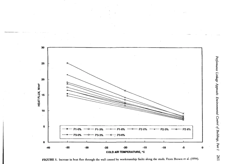
As Bankvall dealt with a hypothetical case of poor design and poor work-manship, Brown et a1. (1993) studied a specifIc case of workmanship faults.
260
JOSEPHW. lSTIBUREK AND MARKT. BOMB ERGEach vertical corner of a wall cavity was partly unfllled (3 and 6% unfilled areas were selected for testing). Wind protection was applied on both sides of the mineral fiber insulation and no continuous and interconnected air spaces and gaps were simulated. These kinds of test conditions appeared to come closer to workmanship faults found in actual walls. Figure 1 shows that with a large difference in temperature, the reduction of wall thermal performance may be as high as 30 percent.
Silberstein and Hens (1996) analyzed the significance of proper design of
ventilated air spaces. It is important to underline that, similar to wall Con-struction, the roofmg deck must also be constructed as an airtight structure.
It was shown, that for an airtight roof deck structure and typical air veloc-ities observed in ventilated cavveloc-ities, the effect of air ingress into the
insula-tion is insignificant.
There is no contradiction between the results of these two studies. Brown
et a!. (1993) stated: "Since the measured thermal resistance ofwalls with 0% defects agreed with predicted values, it is evident that the material is
per-forming as expected; consequently, the issue of installation practice needs to
be examined." The authors also stated: "It appears that the convective flow was initiated in the cross-section between the hot/cold pair of air gaps and then spread through the rest of insulation. A contributing factor is that the air permeability along the MFI product, the manufacturing plane, is much higher than across the product."
This explanation follows findings of Wilkes etal. (1991), who showed the
sig-nificance of convection initiators on the onset of conVection. Tbis closes a loop
between practice and understanding. The transition zone to fully developed natural convection in horizonrallayers was already shown by Wilkes and Rucker (1983), but with the more recent research of Wilkes ot al. (1991) and Brownet
al. (1993) the role of convection initiators was fIrst understood.
In practice, reduction in thermal performance ofinsulation caused
by
con-vective effects was observed at NRC by Wolf et a!. (1966) on wood-frame walls and Sasaki (1971) on steel-stud walls. The latter paper discussed the ef-fect of air gaps caused by a 6 mm lip on the flanges of the steel studs. Brown (1986), testing fourteen different configurations of sheet steel walls, in-dicated similar causes for poor performance of some of the tested sheet steel walls. Thus, not the findings on thermal performance derating, but enhanced understanding ofthis derating mechanism constitutes the progress ofthe last thirty years.
This example also highlights interactionMof environmental control with quality control and workmanship issues.
THERMAL PERFORMANCE-CONFORT AND HEALTH
depres-30
5 25
FIGURE 1. Increase in heat flux through the wall causedbyworkmanship faults along the studs.. From Brown et al. (1994).
tl'
'*'
セセ•
"
t-' セM :.-セセ セ"
a
セ セ ttl•
s
a
•
セ セ•
!i
Q
•
it
"'-.\1'
セo\i
Mセ 0;p
"
....
tv 0' --5 -10 -25 -20 -15COLD AIR TEMPERATURE, 'C
-30 -35 -40 o --- Pl-0% - - 0 - -Pl-3% - . - Pl-6% ---<>---- P2-0"lo セ pRセSE - - - 6 - -P2-6% - e - -P3-0% ----0--=-P3-3% -x-.,P3-6% 20
E
§:•
><
I . :: 15...
l-e[ W :I: 10262
JOSEPHW. lSTIBUREK AND MARKT. BOMBERGsian of temperature on the inner surface of a thermal bridge (TB). At these
locations (in cold climate), lowerthermal resistancereduces the surface tem-perature.
The following aspects of thermal and moisture performance of thermal
bridges in external walls may need to be analyzed:
• depression of surface temperature for a TB located in the clear wall area • effect of increased air mm resistance on depression of surface temperature
(for a TB located in a corner of walls and spaces with restricted air circula-tion)
• effect of thermal properties of the adjacent material layer on depression of
surface temperature
• dust marking caused
by
surface temperature depression (aesthetics) • moisture accumulation causedby surface temperature depression (effectsofTBs on durability of the structure and health of the occupants, see later text)
MOISTURE EFFECTS-MATERL1L DUR,1BILITY
The building envelope must perform. retaining its structural integrity, while separating the interior and exterior environments. Of all
environmen-tal conditions, moisture poses the biggest threat to the integrity and
durabil-ity of materials in building envelopes. Many construction materials contain moisture, most notably, masonry or concrete. These materials demonstrate excellent performance as long as the moisture does not compromise their structural or physical integrity. However, excessive moisture jeopardizes
both the material and its functionality,
Consider, for example, the ability of a material to withstand, without
de-terioration, natural periods of freezing and thawing. As already mentioned,
the frost durability is not a material characteristic, but a complex property
which depends on the material, the construction system, and the environ-ment. For instance, in one school building, only the outer surface of the
ex-ternal clay-brick protrusions showed freeze-thaw spalling. These
protru-sions were more exposed to driving rains and the surface temperature of the
bricks was slightly lower, compared to the plain facade where no spalling
occurred. Both of these conditions contribute to increased risk for
freeze-thaw damage.
One may also observe interaction of temperature and moisture in other
types of moisture originated damage, e,g., corrosion and mold growth. The
rate of corrosion of metals exposed to air varies with both the surface
tem-perature and air humidity (Grodin, 1993). Mold growth requires
coinci-denceof bothcertain temperatures and humidities [temperatures above SoC
Performance Linkage Approach: Environmental Control of Buildings, Part I 263
Indoor Environment: Comfort and Air Quality
Ventilation is required for the health and comfort of the occupants. Ven-tilation is the process of removing and supplying air to and from the indoor
space. Controlled ventilation is defined here as mechanically supplying
out-side air and exhausting inout-side air to maintain adequate indoor air quality (air change), and supplying air for combustion devices and air extraction systems
(air supply).
Natural ventilation (infiltration/exfiltration driven by the stack effect and wind) through random and discrete openings such as operable windows,
doors, ductwork, or holes is not adequate because of the lack of consistency of the driving forces. The instantaneous infiltration/exfiltration rates vary substantially due to the influences of wind pressures, stack pressures, and pressures induced by air-consuming devices. Thus, some areas of a house can have adequate air change at one moment, and inadequate at the next. The variation can be so substantial that the infiltration/exfiltration rates may be on the order of several hundred Etres per second during a wind gust, and
moments later, zero, if the wind suddenly dies down and the majority of the leakage openings happen to falI along the neutral pressure plane.
Mechanical ventilation involves the provision of a controlled driving force to remove and supply ventilation air through either deliberate, discrete
openings or through random openings. This driving force can be provided
on a continuous basis or, as necessary, to remove specified pollutants. Thus, to control indoor air quality, one may either provide sufficient ventilation to dilute the pollutants existing within the indoor space or control the rate of pollutants generated within the indoor space. Designers and builders have to
decide whether to approach the IAQ through ventilation or through source control or both.
Sources can be controlled at the point of generation (point source control
of pollutants/odors) such as the direct venting of combustion appliances and installation ofrange hoods in kitchens or by prohibition (exclusion) such as the regulation of formaldehyde adhesives in building materials, the banning
of unvented kerosene space heaters, the requirement to store firewood out-doors, and the pressurization ofcrawl spaces and basementstoexclude radon
gas.
Pollutant concentrations are only one of the components defining the in-door environment of a building. The inin-door environment also involves comfort factors such as temperature, relative humidity, and air velocity; physical stressors such as noise and lighting; psycho-social factors such as
personal relationships, work stress; and, chemical, particulate, and biological
concentrations. A further complication is often the difference between real
264 JOSEPHW. lSTlBUREK AND MARK T. BOMBERG
-the interrelationships between -the indoor environment, indoor air quality, and comfort factors is illustrated in Figure 2.
The relationships of factors shown in Figure 2 involve health, safety, dura-bility, comfort, and affordability concerns as well as questions about
con-struction performance (warranty).
HVAC Considerations
The design and construction of the building envelope (the walls, roof, and foundation) significantly affect the design of the heating, ventilating, and air-conditioning (HVAC) systems. At the same time, the design, installation, and operation of the HVAC system affects all aspects of indoor climate and building envelope durability. Air movements induced by HVAC may affect
pollutant migration, rain penetration, condensation, and drying of moisture
within building cavities, i.e., the durability of the building envelope. As long as buildings were leaky and poorly insulated, the extent/effect of HVAC systems (and air-consuming appliances) on air pressure fields was
small. There was no need to understand air movement in the building, other
than ensuring that a necessary supply of fresh air was provided. This is not the situation today. Now, we have well-insulated, airtight buildings and in-creased incidence of health problems (mold/microbial contamination) and
deficient long-term performance (metal corrosion and other moisture
orig-inated deterioration). Air flow carries moisture which。エイセ」エウ materials' long-term performance (serviceability) and structural integrity (durability). Air
flow impacts the spread of smoke in a fIre situation, distributin ofpollutants,
and location ofmicrobial reservoirs (indoor air quality). Air exchange affects
energy for space heating or cooling. .
The key to all of these real or potential problems is the understanding of air pressure fields in the indoor and interstitial spaces of the building enve-lopes. Today, understanding the air flow in a building is a necessity. Air pressure gradients (differences in the indoor-air pressure fields), however small and difficult to measure, are needed to establish performance of the building as a system.
A STRATEGY
m
CONTROL AIR PRESSUREA strategy to control air pressure in the building space includes the
fol-lowing steps:
I. Enclose the air space
2. Use controlled mechanical ventilation
3. Control air pressure fluctuations in.duced by HVAC system operational
conditions
-I
i
Performance Linkage Approach: Environmental Control of Buildings) Part I 265
266
JOSEPHW. LSTIBUREK AND MARKT. BOMBERG4. Control air pressure gradients induced by HVAC system operational
conditions
5. Eliminate interconnected internal cavities communicating with HVAC systems
6. Review building mezzoclimate for differences in wind and solar shading
conditions
To control the air pressure field, you must first enclose the air space. To en-close the air space, one should use a mechanical ventilation system. Thus, a controlled mechanical ventilation system should be used anywhere, in small houses -and in high-rises. The next. step is to quantify the degree. of
air-tightness for any building envelope. The National Building Code of Canada (Swartz, 1995) made this requirement mandatory and provided performance
objectivesfor the testing and evaluation of these systems.
While the need to control the pressure fluctuations (in time) and pressure gradients (in space) is recognized, the effect of pathways created by external
cavities and interconnected internal cavities communicating with HVAC
systems on performance of building systems is seldom mentioned. The
sig-nificance of these elements, mostly neglected in the traditional analysis of air
pressure fields, will be illustrated in the few examples selected from case studies (Lstiburek, 1992, 1994, 1995).
The following two examples involve the effect of pathways created by
ex-ternal cavities and interconnected inex-ternal cavities communicating with
HVAC systems. The first one (Figure 3) involves a leaky return duct (actually
it was the housing of an air handler) enclosed within an interstitial space. The second one (Figure 4) involves a plenum return ceiling communicating with an exterior wall.
Figure 3 illustrates a demising wall communicating with a leaky return
duct in a building located in a hot, humid climate. The leaky return duct
created a negative pressure. Since the cavity in the demising wall is con-nected with,the furring space in the exterior wall, the interconcon-nected cavities
can extend the effect of the leaky duct for a great distance. In the actual case
study, moist outside air was drawn into the building cavities even though the interior space was positively pressurized.
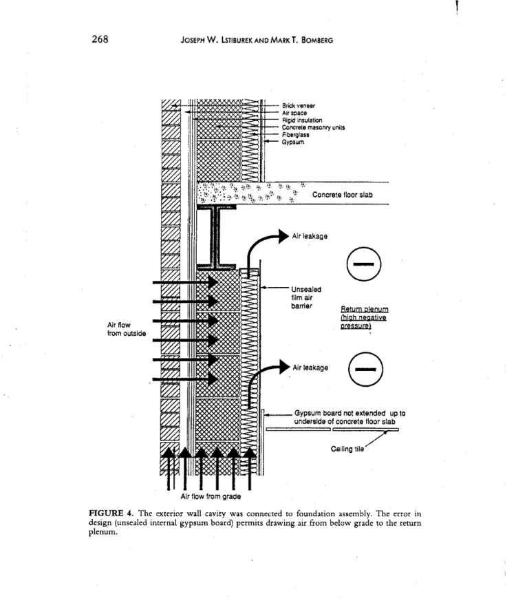
Figure 4 illustrates a plenum return ceiling which is not sealed at the
ex-terior perimeter wall in a building located in a cold climate. Plenum return ceilings operate at negative pressures which may range from 1 to 2 Pascal
(negative to the interior space) to 20 to 30 Pascal (negative to the interior
space). When the plenum return ceiling is also negative to the exterior, out-door air can be drawn into the plenum return through the exterior wall
assembly. The error in the design· shown in Figure 4 had caused additional
Performance Linkage Approach: Environmental Control of Buildings, Part I 267
".:+-R/;"!---+"-It!'----Brick ....eMflr
)--;-....
セihMMM Concr,te masonrywall Jrtl---Air IS、セキョ throUl;lh thelumng space behind the
gypsumboard (lurring
stnps, arll not cononuous)
Interior spausareal a
posittve pl'8ssure I'8lative
10the exterior
-8---
\... Cavity--
Ip.I<::eSwi'ltlin me \demising waUareat •
O
ヲMセGMゥyQセG negative pntSSlJte relative tothe extenol'' - Metal studsar,perfOl'1.led.
r.p
permitting air tobedraWn\:!/ ャエiセィ mewallca...rues
FIGURE 3. Negative pressure created by the leaky return duct draws moist external air into the w;1ll cavity of the building located in hot and humid climate.
to the crawl space. Moisture and pollutants were drawn into the return air plenum.
Ducted distribution systems in conditioned spaces traditionally have not been thought to affect interior air ーイ・ウウセイ・ウN They have been viewed as in-terior air circulation systems which move air from place to place within a conditioned space, with more or less a neutral effect on the pressure differences between zones within occupied spaces. Typically, entire building enclosures are designedto operate under slight positive pressures with pres-surization achieved by providing more outdoor air supply than indoor air exhaust. This pressurization is assumed not to be affected by the interior air circulation systems.
BUILDING ENVELOPE AND HVAC SUBSYSTEMS INTERACTION
The following two examples illustrate the significance of ducted distribu-tion systems on interior air pressures. The first one (Figure 5) involves the leakage of supply ducts installed in an exterior space (vented attic). The sec-ond one (Figure 6) involves the effect of closing doors in a facility with in-adequate provision for return air.
Figure 5 illustrates a facility. located in a hot, humid climate with leaky supply ducts located outside of the conditioned space in a vented attic. Air
268
JOSEPHW. LSTIBUREK AND MARKT. BOMBERGLセ ゥセZ C t II I b
ZセZ HセZB [セZ [セZ onere e oor s a
Gypsum board not extended up to
undersJde of concrete Iloor slab
8
8
Return plenum (hjgh negative IlW.SJJ.W Ceillngtile7
Brick veneer Air space Algid insulation Concrele masonry units Fiberglass GypsumI
セ⦅N Air leakage ;:jl---Unsealed flIm alr barrier [ZェャャNNッッMセ Air leakage Airflow from outsideAir flow from grade
FIGURE 4. The exterior wall cavity was connected to foundation assembly. The error in design (unsealed internal gypsum board) permits drawing air from below grade to the return plenum.
Performance Linkage Approach: Environmental Control of Buildings) Part I 269
セMMQセイZNMMLセMMLセセセ\]MMM Leaky supply ducts
--' inattic
;:,.-1----
Depressurizedconditioned space
inducinginfiltration
..1:;==--crawlspace
FIGURE 5. Negative pressure created in the conditioned space by leaky supply ducts located in the attic of the building located in hot and humid climate.
leaking out of the supply ducts depressurizes the conditioned space, induc-ing the infIltration of exterior hot, humid air.
Figure 6 illustrates a facility located in a cold climate with inadequate pro-vision for return air. When interior doors are closed, individual rooms/spaces can become pressurized with respect to common areas. The common areas, in turn, become depressurized. If atmospherically vented combu.stion appliances (such as fireplaces and gas water heaters) are located in the common areas, the negative pressure in these regions can lead to spill-age and backdrafting of combustion appliances. In the pressurized rooms! spaces, the forced exfiltration of interior (typically moisture laden) air can lead to condensation and moisture induced deterioratipn problems.
In most mid-rise and high-rise buildings, the stack effect air flows typi-cally dominate the HVAC system air flows. Stack effects are shown sche-matically in Figure 7. Note that the majority of the air pressure drop is taken by the exterior building envelope at the top and bottom of the building. Air flows from the lower units and floors, up the elevator shafts, stairwells, and service penetrations to the upper units and floors. These stack effect induced
Bedroom Hall Bedroom
®
8
®
Supply Return Supply
QGセセセOiiiiiセQG
FIGURE 6. Pressure differences in the indoor space created by inadequate provision for return airwhen doorsare closed.
,
,-...
\' |セ \' \"\
-セ
セ
セ
E
;---:
/ / / / I-Flow from outside through lower units into corridor and elevator shaft
N
...
o セ§
or セ セ セセ
セ セ cf
セ ;-<i
m i:lFIGURE7. Air pressure distribution in a mid-rise building.
Performance Linkage Approach: Environmental Control of Buildings, Part I 271
air flows are often responsible for pollutant tnigration, odor problems,
smoke and fire spread, elevator door closure problems, and high thermal
operating costs.
More desirable conditions are achieved by sealing units from corridors
and by isolating corridors from elevator shafts (vestibules), air flows caused by stack effects are significantly reduced. The forces acting on this
eight-story building have been reduced by "compartmentalization." In essence, this
building behaves in a similar fashion to eight, one-story buildings located on
top of each other. The pressure drops are now taken across the corridors and elevator vestibules, not the exterior building envelope. This results in a safer
building with respect to smoke and fire control. Indoor air quality problems are reduced and energy efficiency is greatly enhanced.
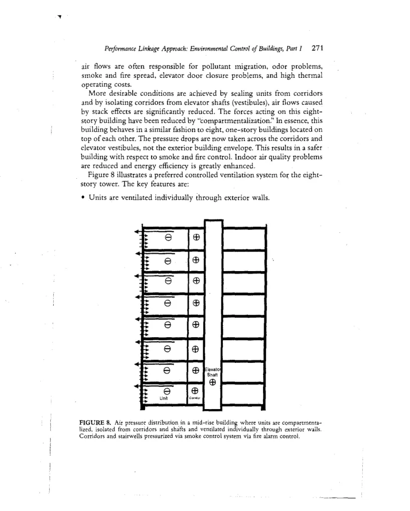
Figure 8 illustrates a preferred controlled ventilation system for the eight-story tower. The key features are:
• Units are ventilated individually through exterior walls.
-セ8
EB
セセ
8
EB
:
8
EB
•
8
EB
e
EB
...
::
e
EB
t
;
e
EB
"Ievato Shaft,.
EB
8
EB
Unl) Cor!<lor...
FIGURE 8. Air pressure distribution in a mid-rise building where units are compartmenta-lized. isolated from corridors and shafts and ventilated individually through exterior walls. Corridors and stairwells pressurized via smoke control system via fire alarm control.
272
Vestibul
Doors
JOSEPH W. LSTIBUREK AND MARK T. BOMBERG
••••••••• I ' .
=
. e...
...
.
I ....
..
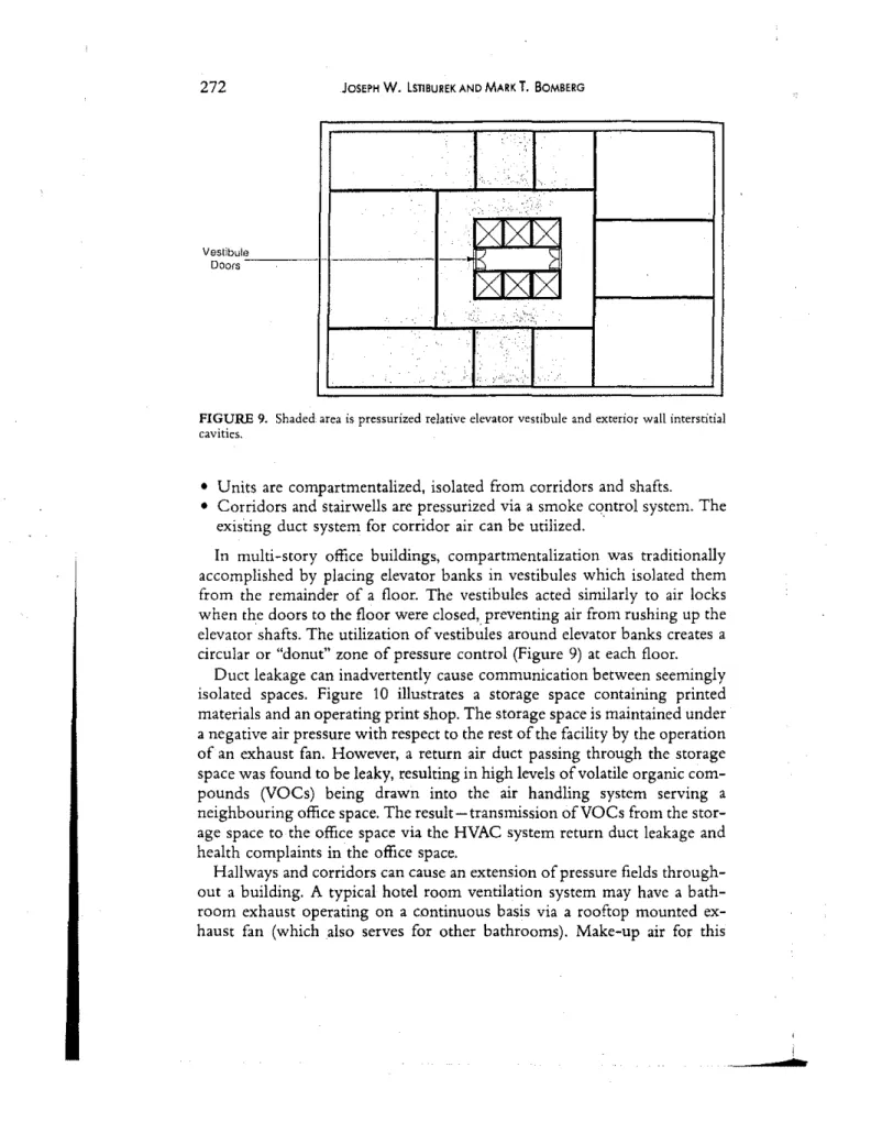
FIGURE 9. Shaded area is pressurized relative elevator vestibule and exterior wall interstitial cavities.
• Units are compartmentalized, isolated from corridors and shafts.
• Corridors and stairwells are pressurized via a smoke cqntrol system. The exis'ting duct system for corridor air can be utilized. '
In multi-story office buildings, compartmentalization was traditionally accomplished by placing elevator banks in vestibules which isolated them from the remainder of a floor. The vestibules acted similarly to air locks when the doors to the floor were closed, preventing air from rushing up the elevator ·shafts. The utilization ofカ・ウエゥ「セャ・ウ around elevator banks creates a circular or "donut" zone of pressure control (Figure 9) at each floor.
Duct leakage can inadvertently cause communication between seemingly isolated spaces. Figure 10 illustrates a storage space containing printed materials and an operating print shop. The storage space is maintained under a negative air pressure with respect to the rest of the facility by the operation of an exhaust fan. However, a return air duct passing through the storage space was found to be leaky, resulting in high levels of volatile organic com-pounds (VOCs) being drawn into the air handling system serving a neighbouring office space. The result-transmission ofVOCs from the stor-age space to the office space via the HVAC system return duct leakstor-age and health complaints in the offlce space.
Hallways and corridors can cause an extension of pressure fields through-out a building. A typical hotel room ventilation system may have a bath-room exhaust operating on a continuous basis via a rooftop mounted ex-haust fan (which also serves for other bathrooms). Make-up air for this
!