Design and Analysis of Production Systems
in Aircraft Assembly
by Andrew Wang
B.A.Sc., Mechanical Engineering, 1997 University of Waterloo
Submitted to the Department of Mechanical Engineering In partial fulfillment of the Requirements for the Degree of
MASTER OF SCIENCE IN MECHANICAL ENGINEERING ACHUSETT
At the LUM
Massachusetts Institute of Technology June 1999
C 1999 Massachusetts Institute of Technology. All rights reserved
Signature of A uthor ... ... . . ... . . . .E n
--Departmen of Mechanical Engi ring
May 7, 1999
C ertified by ... .. ... David S. Cochran Assistant Professor of Mechanical Engineering Thesiwasi yisor
A ccep ted b y ...
Ain A. Sonin Chairman, Department Committee on Graduate Students
Design and Analysis of Production Systems
in Aircraft Assembly
by Andrew Wang
Submitted to the Department of Mechanical Engineering on May 7, 1999 in Partial Fulfillment of the
Requirements for the Degree of
Master of Science in Mechanical Engineering
ABSTRACT
In complex manufacturing systems such as aircraft assembly, it is difficult to coordinate the design of all the elements that comprise the system to work together effectively in achieving the overall goals. This thesis presents a methodology for analyzing a current production system to understand how the design attributes interrelate and the method to redefine those attributes based on the principles of lean production.
First, a case study on wing assembly comparing five different sites is presented to assess the current state of production system design in airframe assembly. From the case study, characteristics about the aircraft industry are determined as well as the differences when compared to the automotive industry and opportunities for further improvement are identified. A second case study shows how one aircraft assembler attempted to implement
the principles of lean production in their plant. This case study presents some
implementation issues and discusses the impact of standardization and setup reduction in manually intensive tasks.
Before the design of a system may be changed, the factors that influence the current design must be understood. In military aircraft programs, the procurement policies have a profound impact on how the manufacturing systems are designed and operated. These effects are discussed to provide understanding for the redesign of those policies and to illustrate that manufacturers must design and operate their systems methodically, instead of allowing them to evolve in reaction to cost accounting and procurement policies.
Finally, a generalized methodology is developed for assessing the design of a production system. This analysis assesses how well the different attributes of a system are implemented and how they interact, providing a tool to aid the design of a lean production system.
Thesis Supervisor: David S. Cochran
Acknowledgements
Acknowledgements
Less than two short years ago, I arrived at MIT in excitement and awe of a prestigious institution at which I would have the honor of working with many talented peers and learn from professors who are leaders in their fields. Looking now at this thesis, I remember not only the research I have done here, but all the learning, mistakes, long nights and friendships made. I am thankful to all those who have helped me along the way, providing a most memorable and rewarding MIT experience.
My first trip to this institution started in despair as my poor planning yielded few potential research projects. To the rescue was of course, Leslie Regan of the ME grad office, who offered much help in finding a research project.
The first meeting with Prof. David Cochran introduced me to a new field. His enthusiasm and perspective on manufacturing motivated me then to start the project and throughout my time here, to approach engineering and problem solving in an entirely new way. I will always be grateful for the opportunities he has provided me and the many talks we have had.
The next encounter I would soon have was with Tom Shields, my sponsor and LAI supervisor. I would not have guessed from this brief meeting that Tom would have such an integral role on my experience here. I am grateful for all his support and continuous feedback.
I still remember my first Factory Operations meeting as I smirked watching my seniors being scrutinized by the faculty members. Little did I know that I too would be subjected to this "academic cleansing" on a bi-weekly basis. To Prof. Timothy Gutowski, Prof. Stanley Gershwin and the rest of the Factory Operations group, I feel lucky to be the only Master's student with regular committee meetings.
As my research assistantship kicked off, I was paired with visiting Prof. Paulo Lima from Brazil. It did not take long to realize that I had found a true mentor, taking whatever time necessary to explain and debate concepts and constantly challenging me with projects.
Venturing into the aircraft industry, I saw many of the challenges required in putting together complex machines of the highest quality and learned many important lessons. I thank the LAI contacts and their co-workers who hosted my stay at their companies and provided valuable advice and insight into their manufacturing systems.
Design and Analysis of Production Systems in Aircraft Assembly
Thanks to the PSD lab for providing me a second home - literally. My fellow PSDer's, Micah, Jorge, Vicente, Jim, Dan, Yong-Suk, Jose, Jochen, Kristina, Alex and Ania made the many times spent together memorable and enjoyable as did my fellow grad students John, Yu-Feng, Melissa, Mike, Derek, Corey and Jamie. Thank you for all your help and good times; best wishes on your future endeavors.
Looking back, I see the loved ones who have supported me throughout, and who may draw this Canadian home. Thanks to the "Gang," Albert, Mike T., Mike L., Aidan, Hannah, Maureen and Wynne for their enduring friendship and brightening visits. With even more visits by Sanjay, Rob, Matt and emotional support from Gina, I never felt far from home.
My deepest appreciation goes out to my family who has always supported me. I feel lucky to have a brother who has shared the excitement and problems throughout our adventures with a special bond. I am grateful to my mother and father for their valued teachings on life, encouragement in education and their uncompromising love and support.
Finally, I thank God for His many blessings and hope that He continually guides my path.
Table of Contents
Table of Contents
ACKNOWLEDGEMENTS... 5 TABLE OF CONTENTS ...---...--... LIST OF FIGURES ...-. - - - -....-- - - - 11 L IST OF T ABLES ...-...--...-- - .. 12 CHAPTER 1: INTRODUCTION ... ... 131.1 C hapter Sum m aries ... 13
CHAPTER 2: BACKGROUND - LITERATURE REVIEW... 17
2.1 Lean Production - The Toyota Production System ... 17
2.1.1 D evelopm ent ... 17
2.1.2 Principles... 18
2.2 A ircraft A ssem bly... 20
2.2.1 D evelopm ent of Assem bly M ethods ... 20
2.2.2 H istory of A ircraft Industry ... 22
2.3 LA I R esearch ... 25
2.4 Production System D esign R esearch... 26
2.5 Contribution ... 26
CHAPTER 3: WING ASSEMBLY CASE STUDY... 29
3.1 M otivation ... 29
3.2 M ethodology ... 29
3.2.1 Selection of Sites... 30
3.2.2 Site Visits ... 31
3.3 O bservations ... 31
3.3.1 Assem bly Process... 31
3.3.2 Scheduling ... 33
3.3.3 Parts Supply... 34
3.3.4 O ut of Station W ork ... 35
3.3.5 Operator W ork... 36
3.3.6 Inspection/Q uality... 36
3.4 R esults of D ata C ollection... 38
3.4.1 Throughput Tim e ... 38
3.4.2 Schedule Perform ance... 43
3.4. 3 Q uality ... 43 3.4.4 O vertim e ... 46 3.4.5 Labor Cost ... 46 3.4.6 O ut of Station W ork ... 48 3.4.7 D elays ... 50 3.5 Sum m ary ... 51
CHAPTER 4: INTRODUCTION TO PSD ANALYSIS ... 53
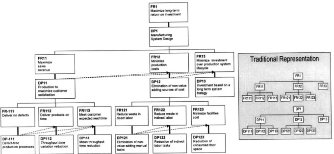
4.1 A xiom atic design ... ... 53
4.2 PSD decom position... 55
4.2.1 D ecomposition of Top Three Levels ... 55
CHAPTER 5: PSD ANALYSIS OF WING STUDY... 59
5.1 Q uality... 59
5.1.1 Stable Processes ... 60
5.1.2 Equipm ent... 61
Design and Analysis of Production Systems in Aircraft Assembly
5 .1 .4 M e th o d s... 6 6
5.2 Throughput Tim e Variation ... 67
5.2.1 Detection & Response to Production D isruptions ... 68
5.2.2 Predictable Production Resources... 68
5.3 Throughput Tim e ... 70
5.3.1 M ean Throughput Time Reduction in Aircraft Industry... 71
5.4 Production Cost ... 74
5.4.1 Elim ination of Non- Value Adding M anual Tasks ... 75
5.4.2 Reduction in Indirect Labor Tasks... 75
5.5 Investm ent... 76
5.6 Sum m ary ... 76
CHAPTER 6: EXPERIENCES IN LEAN IMPLEMENTATION: B-2 CASE STUDY...79
6.1 Background... 79
6.1.1 Scope of Study... 80
6.2 M ethodology ... 80
6 .2 .1 S tra tegy ... 8 0 6.2.2 Timeframe... 81
6.2.3 Lean Implementation Team - Initial Effort... 81
6.3 A nalysis... 82
6 .3 .1 Im p a c t ... 8 6 6.4 Discussion...89
6.4.1 Reaction to Change... 89
6.5 Sum m ary ... 89
CHAPTER 7: BEYOND FACTORY OPERATIONS ... 91
7.1 Special Factors in M ilitary Aircraft Program s... 91
7.1.1 Product Performance and Quality... 91
7.1.2 Production Investment ... 92
7.1.3 Cost Negotiations... 93
7.2 Axiomatic Design Analysis of Military Aircraft Production Systems... 94
7.2.1 Increase Sales Revenue... 95
7.2.2 M inim ize Production Cost ... 96
7.2.3 M inim ize Production Investment ... 97
7.3 Conflict w ith Production System Design Decom position ... 98
7.3.1 Quality - Stable Processes... 99
7.3.2 M ean Throughput Time... 99
7.3.3 Production Cost... 99
7.3.4 Production Investment ... 99
7.4 Sum m ary ... 99
CHAPTER 8: PRODUCTION SYSTEM DESIGN EVALUATION...101
8.1 M otivation ... 101
8.1.1 D efining a "Good" Design... 101
8.1.2 Impact of Evaluation M ethods on System Evolution... 102
8.1.3 Current "Lean" Production Assessments... 102
8.2 M ethodology ... 103
8.2.1 Development from PSD decomposition ... 103
8.2.2 Qualitative Assessment of FRs based on the Information Axiom ... 106
8.3 PSD Evaluation Tool... 108
8.4 Analysis using PSD Evaluation Tool... 110
8.4.1 Evaluation ... ... 110
8.4.2 Interactions ... 8.4.3 M etrics ... ... ... .116
Table of Contents
CHAPTER 9: CONCLUSIONS ... ... --.. ---... 119
9.1 From W ing Assem bly Case Study... 119
9.1.1 Quality - Stable Processes... 119
9.1.2 Throughput Time Variation ... 121
9.1.3 M ean Throughput Time ... 122
9.1.4 Production Cost - Direct Labor ... 123
9.1.5 Production Cost - Indirect Labor... 123
9.1.6 Production Investment ... 124
9.2 From B-2 Case Study ... 124
9.3 From Analysis of M ilitary Aircraft Procurement Policies... 125
9.4 From PSD Evaluation ... 126
REFERENCES ... 127
APPENDIX A - LAI RESEARCH PLAN... 129
APPENDIX B - SAMPLE HYPOTHESIS TESTING EQUATIONS ... 131
Testing for a difference in mean between two samples... 131
Testing for correlation of data (Using Pearson's correlation) ... 132
APPENDIX C - D ESIGN OF DELAY Q UESTIONNAIRE ... 133
APPENDIX D - PSD D ECOM POSITION... 135
List of Figures and Tables
List of Figures
Figure 1: History of U.S. aircraft production... . 24
Figure 2: History of U.S. military aircraft procurement ... 25
Figure 3: Flow of parts, out of station work and expedite signals ... 36
Figure 4: Planned throughput time vs. Number of BOM line items ... 39
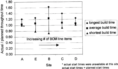
Figure 5: Normalized build-times at wing assembly sites ... 41
Figure 6: Normalized build-times at engine assembly sites [Ramirez, 1998] ... 41
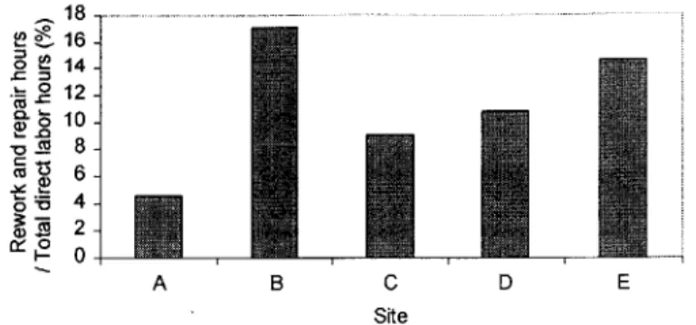
Figure 7: Rework and repair hours / Total direct labor hours at each site ... 44
Figure 8: Im pact of quality on labor cost... 44
Figure 9: Impact of quality on throughput time... 45
Figure 10: O vertim e w orked at each site ... 46
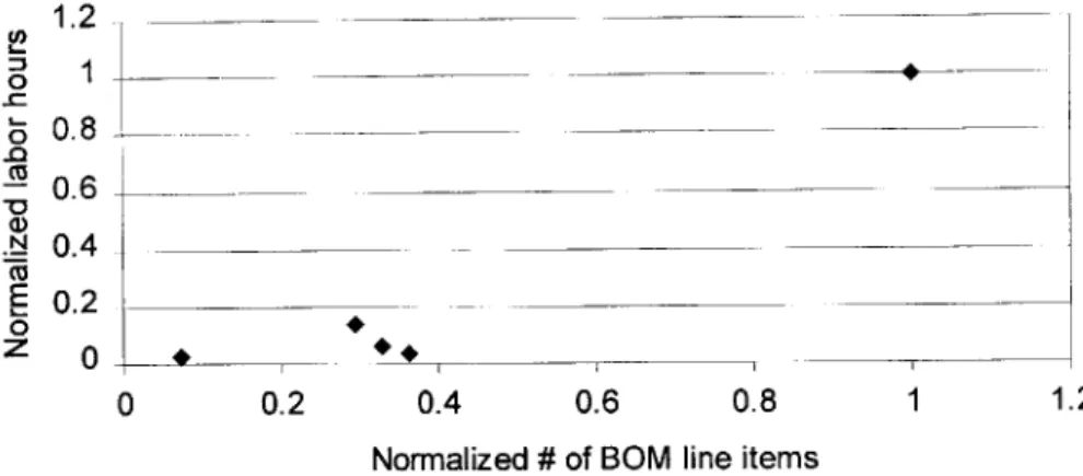
Figure 11: Labor hours vs. BOM line items at the different sites... 47
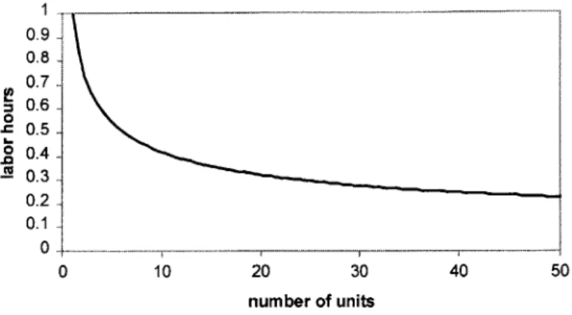
Figure 12: Learning curve used to estimate number of labor hours of first unit... 48
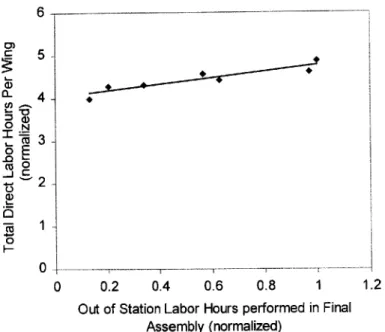
Figure 13: Labor hours vs. Out of station work... 49
Figure 14: The 4 domains in axiomatic design... 53
Figure 15: Types of design (impact of design matrices)... 55
Figure 16: Top three levels of PSD decomposition... 56
Figure 17: Further PSD decomposition topics... 58
Figure 18: Decomposition of FR-Ill: Deliver no defects... 60
Figure 19: Decomposition of FR-Q1: Stabilize process ... 61
Figure 20: Decomposition of FR-112: Deliver products on time ... 68
Figure 2 1: Decomposition of FRI 13: Meet customer expected lead time ... 71
Figure 22: Decomposition of FR-Ti: Reduce run size delay... 72
Figure 23: Decomposition of FR-T2: Reduce process delay ... 73
Figure 24: Decomposition of FR12: Minimize production costs ... 75
Figure 25: Kitting and material handling redesign on the B-2 ... 83
Figure 26: Impact of standard work in the system... 84
Figure 27: Rework hours / total labor hours - before and after lean ... 86
Figure 28: Overtime hours / total labor hours - before and after lean... 87
Figure 29: Throughput time - before and after lean... 88
Figure 30: Total labor hours for tape application process before and after lean projects (exponential learning curve fitted to first four units)... 89
Figure 31: Top Level decomposition (military aircraft impact) ... 95
Figure 32: Decomposition of FRm Ii: Increase sales revenue (military aircraft impact) ... 95
Figure 33: Decomposition of FRm12: Minimize production costs (military aircraft impact) ... 96
Figure 34: Decomposition of FRm 13: Minimize production investment (military aircraft impact)... 98
Figure 35: Military aircraft production decomposition... 100
Figure 36: Typical Lean Evaluation Chart ... 103
Figure 37: Mapping of evaluation FRs to PSD decomposition [Cochran et al., 1999]... 104
Figure 38: Example of qualitative assessment that an FR is satisfied ... 107
Figure 39a: PSD Evaluation Tool (page 1 of 2) ... 108
Design and Analysis of Production Systems in Aircraft Assembly
Figure 41: Exam ple of evaluating an FR using the pie-chart system ... 111
Figure 42: Interactions of quality - stable processes ... 112
Figure 43: Interactions of throughput tim e variation... 113
Figure 44: Interactions of m ean throughput tim e (delay reduction) ... 114
Figure 45: Interactions of direct labor ... 115
Figure 46: Interactions of indirect labor ... 116
Figure 47: M etrics for each FR ... 117
Figure 48: Impact of variation on manufacturing lead-time (planned throughput time) ... 122
List of Tables
Table 1: Sum m ary of Sites visited ... 30Table 2: Reasons for Delay... 50
Table 3: Evaluation of on the job training in w ing assem bly ... 63
Table 4: Standard w ork rating in w ing assem bly... 64
Table 5: Standard w ork evaluation for B-2... 84
Table 6: W ork instruction rating in w ing assem bly ... 85
Table 7: Custom er N eeds... 94
Introduction
Chapter 1:
Introduction
Throughout history, transformations in industry have often been stimulated by a "crisis situation" or need, followed by a technological advancement to satisfy it. As military spending decreases from that of the cold war, aircraft companies and the military alike have concentrated efforts on delivering the highest amount of defensive capability with the lowest cost. Part of this strategy is to reduce the manufacturing costs but marginal improvements in operating efficiency would not be enough. However, through studies in the automobile industry, it has been found that very significant improvement in cost, quality, and throughput
time may be achieved through a different approach to manufacturing. This approach
originated from the Toyota Production System (TPS) [Monden, 1998] and has since been named "Lean Production" [Womack et al., 1990]. Many other industries have taken note of TPS and have adopted their methods with varied success. This has spawned many consulting and research activities to teach the principles and tools of TPS so that companies may be successful in its implementation.
This thesis focuses on the implementation of lean production in airframe assembly through analysis of the production system design. With its application, it is hoped that the Air Force can maintain high quality defense capabilities in the face of decreased military spending. With these methods applied to the private sector, the opportunity for marked increase in manufacturing efficiency and capability may give companies the advantage they need to compete with domestic and foreign competitors.
1.1 Chapter Summaries
To provide a succinct description of the organization of this thesis, each chapter is briefly summarized. It also outlines the flow of ideas and provides the context for which each chapter is written.
Design and Analysis of Production Systems in Aircraft Assembly
2. Background - Literature Review
This chapter describes briefly the development of lean production and how it has changed the way production systems are being designed and how businesses are being run. Some background on aircraft assembly is presented to set the stage for the need to change the manufacturing methods in the industry. Current research on these topics by the Lean Aerospace Initiative (LAI) and the Production System Design (PSD) laboratory are outlined and the contribution of this thesis is stated.
3. Wing Assembly Case Study
This chapter presents a case study comparing the wing assembly operations of five sites to assess the current state of aircraft assembly. Observations of the assembly operations are made and data on throughput time, quality, labor hours and delays are presented to
characterize the industry.
4. Introduction to PSD Analysis
To further understand what lean production means, the PSD decomposition [Cochran, 1998] is proposed as a model. This section explains the PSD decomposition - an axiomatic design decomposition of a generalized manufacturing system - in more detail. This theory will act as the basis for much of the analysis in the chapters that follow.
5. PSD Analysis of Wing Study
This section is the analysis of the wing assembly case study using the PSD decomposition as a framework. It provides further insight into the problems observed in the system and outlines an approach to deal with these issues. The PSD decomposition, applicable to a wide range of industries, is discussed with respect to how it specifically applies in a low volume, low process capability, highly manual assembly environment as in the aircraft industry.
6. Experiences in Lean Implementation: B-2 Case Study
The B-2 case study serves as an example of setup reduction and standardization in manual work content and the impact on the total production system design. The results of these
Introduction
changes, the methodology and the lessons learned of the implementation will also be further discussed. The purpose of this chapter is to show how some of the recommendations have been put into practice and how they have impacted the system.
7. Beyond Factory Operations
One of the barriers identified in lean implementation is the procurement policy issue in military programs. The impact of these policies and how they have influenced production system design and operation is presented. An axiomatic design decomposition of how manufacturers respond to procurement policies is used in contrast with the decomposition of a lean system. Recommendations on rethinking the procurement policies to promote lean production are made.
8. Production System Design Evaluation
This chapter presents the Production System Design Evaluation Tool developed based on the PSD decomposition and from the analysis used in the wing assembly case. The motivation for such a tool, the methodology in developing it and how it is applied will be presented.
9. Conclusions
Background - Literature Review
Chapter 2:
Background - Literature Review
This chapter describes briefly the origin of lean production to describe a system design and how the system design changed the way businesses are being designed and run. Some background on aircraft assembly is presented to set the stage for the need to change the manufacturing methods in the aircraft industry. Current research topics in Lean production and production system design by the Lean Aerospace Initiative (LAI) and the Production System Design (PSD) laboratory respectively are outlined. The contribution of this thesis is also stated at the end of this chapter.
2.1 Lean Production - The Toyota Production System
Lean production - coined by the International Motor Vehicle Program (IMVP) in their study on the auto industry [Womack et al., 1990] - has caught the attention of manufacturers all over the world. The manufacturing system design represented was developed by Toyota [Cochran, 1994] from the 1940's to the 1970's [Monden, 1998] has since been displayed, taught, studied and even implemented widespread across many industries and countries. In operations management books, TPS is being referred to as "Just in Time" manufacturing [Spearman and Hopp, 1996]. The benefits reported in the automotive industry [Womack et al., 1990] have been astounding with claims of improved quality, lower production costs, shortened delivery and product development time and greater flexibility.
2.1.1 Development
It was not until after the oil crisis of 1973 that the industrial world took note of Toyota Motor
Corporation's manufacturing prowess [Shingo, 1989]. However, the principles of TPS
developed from the 1940's during a time when Japan was in a post-war rebuilding stage and resources were scarce. At that time, Japan's automotive industry was insignificant and labor productivity was one ninth that of the U.S. [Spearman and Hopp, 1998]. Because Japan's automobile market was small, they could not compete with just the economies of scale realized by mass production. Toyota concentrated on reducing costs by eliminating waste
Design and Analysis of Production Systems in Aircraft Assembly
and producing a greater variety of vehicles in smaller numbers with the shortest possible lead time. The challenge was to produce this wide range of vehicles in a regular production routine with very limited resources and without holding large levels of inventory. Toyota responded to this challenge with the development of a production system design that rests on two pillars, Just-in-time, and autonomation (Jidoka - automation with a human touch).
2.1.2 Principles
The idea of just-in-time came from Kiichiro Toyoda; Taichi Ohno's implementation of JIT came from the observation of American supermarkets where customers took the products they needed, when they were needed and in the amounts that were needed. The shelves would then be replenished as they were being emptied, signaling orders in response to actual customer demand. In the manufacturing version of this analogy, the downstream customer takes only the parts needed from standard inventories and upstream sub-systems are signaled to produce based on what is taken. To implement the pull systems, Kanban - the Japanese term for card - were used to advance parts for assembly and to signal upstream production as
material is consumed. To avoid large amounts of inventory, the throughput time and
response time of the manufacturing system was minimized by production leveling, product flow oriented layouts and single piece flow. Autonomation allowed further cost reductions through separation of worker and machine, leading to cellular manufacturing [Black, 1991].
To level production and thereby achieve low levels of inventory, the production schedule must first be very regular, both in terms of volume and product mix. Toyota translated total demand over a month to a takt time, which was the time interval that vehicles are produced. This takt time paced production to ensure that processes did not work ahead and then fall behind, causing surges that require inventory. Because Toyota produces a wide range of vehicles, leveling the different product types has a great impact on the ability to reduce inventory. Instead of producing large batches of each product type at a time (1000 A parts, 2000 B, 1000 C), parts are leveled so that model mix is maintained over the smallest time frame possible (10 A, 10 B, 10 C, 10 B). To achieve this mixed model production, setup times were reduced dramatically through single minute exchange of die [Shingo, 1989]. This
Background - Literature Review
was a unique approach to reducing the cost of set-ups, which was traditionally minimized by setting optimal lot sizes, assuming set-up time was constant.
In product flow oriented layouts, there may be more total machines than in a job-shop layout. To reduce the number of workers necessary, workers must be able to run several machines [Cochran, 1998]. To do this, the machines would have to run independently, automatically stop, and detect errors, eliminating the need for machines to be monitored. Operators would typically load a machine (a task difficult to automate) and move to the next machine as the
machine cycles automatically and unloads the part (easy to automate task). These
characteristics describe automation with a human touch - autonomation. In combination
with cross-trained operators and standard work routines, cellular manufacturing was developed which added volume flexibility and improved utilization of workers [Charles et al., 1999].
In addition to some of these innovations, Toyota also applied common sense ideas with exceptional execution. The Japanese term Kaizen, refers to the continuous implementation of small improvements [Monden, 1997] towards the goals of zero defects and total waste elimination to achieve a given takt time with a minimum of labor. Toyota fostered the philosophy of eliminating all root causes of problems so that they never cause another disruption or defect. Although stopping to correct all problems as they occur is very disruptive, it eventually improves the predictability of the system. Ohno identified seven wastes, overproduction, delay, transport, processing, inventory, wasted motion and the waste of making defective products. Further improvements followed the application of 5S, which refers to a clean and ordered workplace with all unneeded materials, tools, equipment, parts and documentation eliminated. With Kaizen applied diligently to these basic ideas, great improvements in quality, cost, timeliness, work environment and safety were realized.
Innovations of TPS extended beyond the factory to product development, supplier relations,
marketing and labor relations. Lean product design involves changes in leadership,
teamwork, communication and simultaneous development [Womack et al., 1990]. The
commitment to make design decisions early in the process and by placing emphasis on manufacturing helped to decrease development time and ensured that designs could be
Design and Analysis of Production Systems in Aircraft Assembly
produced. Instead of "pitting" suppliers against each other to get the best price, Toyota established long term relationships with suppliers and worked with them to improve quality and decrease cost. To establish confidence in production rates, considerable efforts are put into market research, maintaining customers, and even using aggressive sales techniques when necessary [Womack et al., 1990]. Toyota also improved the effectiveness of the workforce by guaranteeing lifetime employment to allow continuous improvement to proceed without the fear of loss of jobs. Perfect attendance programs and work teams were also developed to minimize production disruptions.
TPS, JIT and lean production have been written about and discussed for many years but companies trying to apply these techniques have encountered many challenges. Although the techniques of TPS were developed since the 1940's, research still continues in this area to develop structured methodologies to explain the principles of TPS and how to implement them. There is also particular interest in investigating how the techniques work in industries where conditions may be different. Factors considered have been volume, customization, complexity, culture, amount of automation, predictability of demand and distance to suppliers. More than anything else, observations of TPS have prompted industries and researchers to realize that traditional ways of doing business must be completely rethought, where every previous assumption is questioned in order to develop more competitive production systems.
2.2 Aircraft Assembly
This section provides some background on the aircraft industry. Although the wing assembly case study in chapter 3 provides current observations into aircraft assembly, some of the history of the aircraft industry is presented to understand the reasoning why these systems have evolved to their current states.
2.2.1 Development of Assembly Methods
When the airplane was invented, the structure was made mostly of wood with fabric coverings and wires. Early craft producers employed artisans who produced individual parts - an approach referred to as piecework [Simonson, 1968]. As aircraft production increased,
Background - Literature Review
assembly line techniques were used (as rates approached one aircraft per hour). Large machines were employed, doing operations on entire subassemblies. To decrease the number of rivets required, spot and seam welding was used. Rivet holes were also made during the blanking of sheet metal parts. Many unskilled workers were also employed and because of the production rate, they only had a few operations to perform over and over again - such as to install 9 fasteners in one specific area of each plane [Sherman, 1992].
By WWII, aircraft were already built mostly of sheet metal, with other parts from forgings, castings, extrusions and bar stock. The most common metals were aluminum alloys, as are still today. To produce large sheet metal parts with complex shapes and tight tolerances was and still is very difficult. In the design stage, these shapes were "lofted," a process used in ship hull design where control points were defined and wooden or metal slivers were slid through guides to obtain the curves. Plaster molds of the part - male and female were produced which became the "masters" from which tooling and jigs were built. The actual
solid model captured the final engineering specifications - the drawings only had the
nominal dimensions. By 1995, Boeing designed the first airplane, the 777 entirely using electronic means. Instead of the physical models, computer generated solid models were used to design the tooling and jigs.
Increasingly, sheet metal parts are being replaced by machined extrusions for the internal structure to allow interchangeability of parts. Skins are still often sheet metal but composites are being used more. Composites offer advantages in strength and weight but are often very labor intensive. Titanium is also used in areas with high thermal stresses. Despite these advances, modern airframe assembly still has characteristics of craft production methods. Fitting large parts/assemblies together in precision jigs often requires trimming or shimming
operations because the large compliant parts are unable to hold the dimensions necessary.
Although aircraft are continually being upgraded with the insertion of new technological advancements, the time frame for these improvements are quite slow in the airframe sector. Fine [1998] estimates major technological advances in airframes occurring roughly every 10 years compared to every 3 years in electronic controls. In addition, commercial aircraft have had the same configuration for many years and "no change in airframe design is foreseeable
Design and Analysis of Production Systems in Aircraft Assembly
in the medium term" [Pavaux, 1995]. With airframe designs that have such long life cycles, improvements made in the assembly process will have a long return period and so are very valuable. This presents an additional motivation to study how to make these operations "lean".
2.2.2 History of Aircraft Industry
Although entire books have been written on the history of the U.S. aircraft industry and the factors that have shaped it, the material presented here is an abbreviated treatment with highlights of points from "The History of the American Aircraft Industry " [Simonson, 1968].
After the invention of the airplane by Wilbur and Orville Wright in 1903, the airplane received very little attention by industry before the war. By 1915, the number of airplane patents issued hindered the manufacture of airplanes since lawsuits would be inevitable. This state may have continued for much longer if not for the sudden demand for warplanes as the U.S. entered the war in 1917. At that time, some aircraft (about 2500) were being built for foreign orders but with the new demand from the Navy and Army Air Corps, the industry output would have to increase by ten-fold, and as quickly as possible. This increase would require immediate expansion of existing facilities and the use of the automobile industry as well. To alleviate the problem of lawsuits from patent infringement, the military drafted a patent licensing agreement which stated that all manufacturers for the government would have use of the existing patents and the government would pay the licensing fees as part of the price of the aircraft. To integrate other industries, the government would supply detailed designs for any part or machine ordered, and aircraft manufacturers began to teach their methods to the automobile industry. As the aircraft industry transitioned to full production in a cooperative environment to prepare for the war, it could not have done so without facilitation by the government and the newly established procurement policies.
By 1918, 14,020 aircraft were produced but orders dropped sharply after the war. Again, the government intervened and passed the AirMail act in 1925 to stimulate civil aviation. Further acts followed allowing greater spending by the post office and military for aircraft. Civil aviation gained popularity after Lindbergh's inspiring trans-Atlantic flights in 1927. Sales went from 21.2 million in 1927 to 71.2 in 1929, more than tripling. This promising and
Background - Literature Review
seemingly booming industry soon slowed in the 1930's due to the depression and sales dropped to 26.5 million in 1933.
In 1940, Roosevelt called for 50,000 aircraft causing a change from job shop to assembly line techniques of Ford. Ford in fact became a major contractor and established a plant at Willow Run to produce B-24s. By 1944, this one plant accounted for almost 10% of all U.S. aircraft in poundage. In March of that year, the production rate reached almost 1 plane per hour
-453 airplanes (B-24's) in 468 hours [Sherman, 1992]. Mass production techniques were now
being used to take advantage of economies of scale to decrease cost. Again, demand far exceeded capacity so Ford again enjoyed the prospect of producing as many planes as possible.
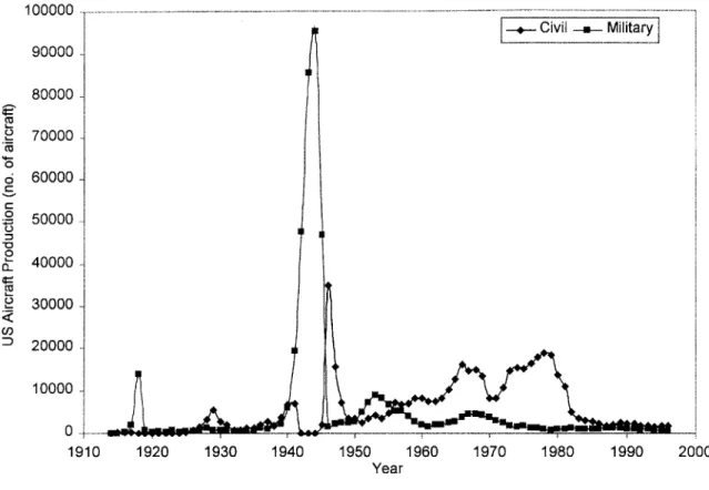
From this brief account, it is obvious that aircraft production is highly dependent on military demand, up to 60% for USA and UK in 1986 [Todd and Simpson, 1986], falling to 37% by 1998 [AIAA, 1998]. This demand has also been characterized with a wave-cycle model, with aircraft production peaking first during WWI, then during WWII and since has oscillated depending on strategic balances in the face of threats to national security as shown in Figure 1. The combination of the surging demand and the large dependence of the aircraft industry on military orders caused great disruption to the industry. In downturns, many companies without commercial business are forced into bankruptcy while the government has to maintain the main contractors with a minimum of orders. Lately, the merger of Boeing and McDonnell Douglas illustrates the combination of military and commercial capabilities to protect against downturns in either business. As an aircraft manufacturer, to set a strategy of maintaining competitiveness in slow periods, observation of how Toyota was able to continue profits after the 1973 oil crisis through their production system would stir great interest - as it has.
Design and Analysis of Production Systems in Aircraft Assembly 0 0 0 0 U) 100000 90000 80000 70000 60000 50000 40000 30000 20000 10000 0-1910 1920 1930 1940 1950 1960 1970 1980 1990 2000 Year
Figure 1: History of U.S. aircraft production'
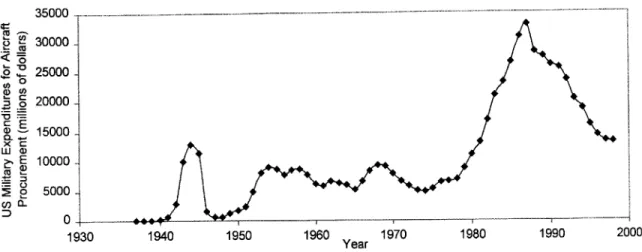
Again, as military spending decreases as shown in Figure 2, efforts are now to make aircraft companies more efficient, so that they may survive this downturn, and maintain U.S. aircraft production capability.
1 Data from Aerospace Facts and Figures 1970 and 1998, by Aerospace Industries Association of America, Inc.
Table: U.S. Aircraft Production Calendar Years 1909 to Date (Number of Aircraft) and Tables: U.S. Aircraft
-Background - Literature Review 35 00 - - - -- - - - -- ----- -- ...~ -. 30000-o 25000 -0 g 20000 -15000 x C E 10000 p5000 -0 .. ... - -1--- - - - -- - -7 1930 1940 1950 1960 Year 1970 1980 1990 2000
Figure 2: History of U.S. military aircraft procurement2
2.3 LAI Research
The design principles of the Toyota Production System transcend the automobile industry, with the lessons being applied in many different industries around the world - including the aircraft industry. Although Lean Thinking [Womack, 1996] alluded to an application of lean production in turbine blade grinding, the aircraft industry at that time had limited application of the TPS principles. The challenge to industry to apply these principles to their respective disciplines was met with the creation of the Lean Aircraft Initiative (now Aerospace) in 1993. This unique combination of government (US Air Force), Labor Unions, academia (MIT) and the private sector (defense aerospace firms and labor unions) intends to transform the industry.
LAI research has focused on identifying best practices from lean production that are applicable in the aircraft industry, as well as potential barriers to implementation. The research efforts are divided between five focus teams - Supplier Relations, Product Development, Policy and External Environment, Factory Operations, and Test and Space
Operations.
Design and Analysis of Production Systems in Aircraft Assembly
The framework used to organize all the research efforts within LAI is the Lean Enterprise Model (LEM) [LAI, 1996] which describe the lean principles and identify the practices. As an ongoing research effort, each of the concepts are continually supported through research by LAI. Selected findings from this thesis will also be incorporated into the LEM as well.
2.4 Production System Design Research
This thesis was written as a collaborative effort between LAI and the PSD laboratory. The PSD lab, headed by Prof. Cochran, approaches research in manufacturing from a systems approach as opposed to concentrating on improving specific operations. The mission is to conduct research in the development of a comprehensive approach for the design and implementation of lean production systems. Thus, the focus is on issues pertaining to design of systems with consideration of product design, machine design, human interface, performance measures, factory layout, and information systems. Through case studies in industry and numerous projects implementing lean production from the product development stage and redesigning mass production plants to cellular manufacturing, the PSD lab has encapsulated the knowledge of TPS from literature and experience in the form of the Production System Design Framework and decomposition [Cochran, 1999]. This work uses Axiomatic Design [Suh, 1990] to analyze how the methods of TPS integrate relationships between concepts and how they satisfy the overall business goals and strategy of the company to make a profit. Reynal [1998] provides examples in the automotive and aircraft industry to illustrate the applicability of the concepts from this design decomposition.
The advantage of using Axiomatic Design to describe TPS is that it provides a structured framework for analysis and further research [Cochran, 1994]. An introduction on Axiomatic design and its use in manufacturing systems is presented in chapter 4.
2.5 Contribution
The contribution of this thesis is the analysis of applying lean production to airframe assembly, an industry where interchangeable parts has not been totally achieved and where there is a high level of manually intensive work as opposed to autonomous stations. Use of the PSD decomposition is also applied in the analysis, which demonstrates its applicability to
Background - Literature Review
the aircraft industry. Axiomatic design is further used to determine the impact of
procurement policies on production systems. In addition, building from the PSD
decomposition is the development of an evaluation tool to aid manufacturers in analyzing their own production systems, identifying fundamental strategic changes for lean production as well as identifying areas to concentrate on to impact the production system design the most.
Wing Assembly Case Study
Chapter 3:
Wing Assembly Case Study
To truly understand the nature of assembling aircraft, one of the most complex products in the world, a detailed view of the industry at many levels would be required. To do this the LAI Factory Operations group proposed a research effort titled "Design and Management of Complex Manufacturing Systems" using case studies to investigate the three main sectors -engines, airframe and electronics - of aircraft assembly. The original research plan is listed in Appendix A. This case study focuses on the airframe assembly sector following the work by Luis Ramirez in the engine sector [Ramirez, 1998].
3.1 Motivation
Each LAI consortium member wishes to learn how to convert a production system founded with a craft mentality in a lean production system. The researchers have been able to
administer surveys and questionnaires but this has not provided the level of detail to reveal implementation issues. This project is designed to delve more deeply into member and non-member companies to understand how to design and manage lean airframe assembly systems.
3.2 Methodology
The approach used was field research at participating initiative member sites. Each site yielded a separate case study and multiple sites were investigated to generalize the overall study. The focus of this project is the study of the performance of the manufacturing system using the key metrics of planned assembly time, actual assembly time, reasons for delay and information about system characteristics. Through a disciplined approach to data collection the major contributors to perturbations in the manufacturing systems are explored for lessons on lean system design.
Design and Analysis of Production Systems in Aircraft Assembly
3.2.1 Selection of Sites
The airframe assembly sites were selected based on the following criteria:
" A group of products/companies that are representative of the defense and commercial aircraft companies in the US (focus on LAI consortium members)
" A group of products that are representative of the different types of aircraft in the defense and commercial sectors
* A group of products that have enough similarities to compare results
* Ability to visit sites over an extended period (typically 1 week) to collect data
The last criterion was undoubtedly the most restricting, especially since the investigator is a Canadian citizen. However, to address the preceding criteria, 5 sites were visited in total, 4 of which for an extended period of time (5 - 8 days) while one was visited for a shorter term (2 days). Companies of different sizes were represented as the study included one large aircraft company and one smaller one. The types of aircraft chosen were 4 military, and 1 commercial. Three were fighter aircraft, one was a large transport, and one was a smaller transport. To limit the scope of the study, only aircraft wings were studied. In addition, only wet wings (wings that are also fuel tanks) were chosen so that the complexity would be similar across the different products. Studying the assembly of wet wings to represent the airframe sector was agreed upon in consensus from the industry, military and academic members of the LAI factory Operations focus team.
Table 1 lists the different sites and some information about each one. Each product has been coded to ensure the security of any propriety information collected.
Table 1: Summary of Sites visited3
System Characteristics A B C D E
Maturity of program 10-15 years > 20 years > 20 years 5-10 years 0-5 years
Production rate 4 3 4 0.67 0.58
Wing Assembly Case Study
Although efforts were made to represent as much of the airframe sector as possible, the sites available did not include a high rate commercial assembler due to restricted access of the plants to the researchers. Unfortunately, this leaves a void in the study as high rate commercial aircraft may operate significantly different from those sites studied. To address this issue, references will be made to a thesis prepared by the Leaders for Manufacturing Program at MIT by Jackson Chao. His study entitled "Analysis of Variance Impact on Manufacturing Flow Time" will be used to include observations made on the Boeing 7A7 aircraft (particular model was not listed).
3.2.2 Site Visits
After each site was identified, it was visited initially for orientation and to familiarize the researchers with the people and data system at the company. The sites would then be followed with a longer visit of approximately 1-week to collect data. In some cases, there was also another visit to collect any missing data or information.
During the site visits, information was collected through a number of means. Conversations with the management, engineers, and crew yielded information using both informal and
formal interviews. Information was also collected through the company's data system.
There were also some efforts made to set up simple data collection procedures to collect data for a period of time.
Although an effort was made to collect the most accurate information, the process used has
its drawbacks. The researchers were generally limited to the production areas of the
companies. Questions better suited for other departments such as design, scheduling, human resources, etc. were answered with best efforts from the people available.
3.3 Observations
3.3.1 Assembly Process
The assembly process of each wing although unique has general characteristics, which are similar throughout the different products. Usually, the wing-box, which is the structural frame of the wing, is built up in a tool/jig with the spars and ribs. Leading and trailing edges
Design and Analysis of Production Systems in Aircraft Assembly
are typically built separately and attached to the wing-box. Then, the skins are fitted and one side is closed off first. Before the other skin is installed, any internal hardware is first installed such as plumbing (for fuel), electronics, and hydraulic systems. The other skin of the wing is then installed.
The sub-assemblies described above are combined at different stages to build up the wing. Sub-assemblies are built in jigs (or tools) where parts can be precision located and held while fastening. Each of these stations is usually called a Work Center. Each Work Center has a designated area, crew, and tasks that are performed. Crew chiefs may lead one or more Work Centers.
Installation of parts requires a special procedure as airframe assembly is classified as type 1I
assembly [as defined by Whitney, 1996] as parts do not locate themselves. (Type I
assemblies are when the locating features are on the parts themselves.) During fabrication of a part, holes are drilled which are then used as reference features during assembly. The part is then located by aligning the reference holes with the jig/tool. Pilot holes are also drilled in fabrication that indicate the location of a fastener between two parts. After locating both parts, the pilot holes (on only one of the parts) are used as a guide to drill through both parts. This ensures alignment of the holes, which would not be achievable by drilling the holes separately in fabrication. Before fastening, deburring and sealing may also be required. Fasteners range from rivets to screws to interference fit fasteners. Because the hole pattern in each part is slightly different, the parts are not interchangeable - parts cannot be removed and fitted on another plane.
The most common material used is aluminum sheet metal and machined parts. Titanium, steel, and composites are also used in different amounts on different wings. The wing is complete when all the skins, panels and plumbing (fuel hoses) have been installed. The whole unit is then mated with the fuselage.
Wing Assembly Case Study
3.3.2 Scheduling
The Scheduling Process
The scheduling process begins with the number of aircraft to be produced per year. In the defense industry, this is determined by the contract and in the commercial industry, it is done by marketing forecasts and/or aircraft orders. The yearly production output is translated into a delivery schedule and using an MRP type of system, each major stage is scheduled by working backwards from these delivery dates (ramp, final assembly, wing, fuselage assembly, fabrication etc.). The times required for each stage are first estimations and may be modified in subsequent scheduling iterations. In each of these stages, the task is further broken down and scheduled into completion dates for each work center. In each work center, there are a number of tasks that must be completed and these are assigned to workers on a daily basis by industrial engineers or the crew chiefs.
Operating Schedules
After the schedule is in the system, it is the information system that coordinates production. It was observed however, at two sites that production was working to "recovery schedules". Due to a production system that has fallen behind schedule, in order to catch up, production had to be sped up in the short term in order to catch up. In these cases, the entire aircraft program would be on this recovery schedule.
At other sites where production was too far behind to catch up to the original plan, an entire rescheduling would be required. Rescheduling would mean that delivery dates would be changed in order to put production back on schedule.
Adherence to Schedule
One difference, between sites that was observed, was management's policies on adherence to the schedule. At one site, the wing would be delivered incomplete to fuselage mate (final assembly) in order to send it on time. This resulted in out of station work to be done in final assembly. At other sites, the wings would not be delivered until a greater degree of completion was achieved, but were often late.
Design and Analysis of Production Systems in Aircraft Assembly
3.3.3 Parts Supply
Parts arrive from different locations such as internal machine shops, external suppliers and other assembly areas producing subassemblies. Most parts destined for the assembly shop floor arrive at the plant and are placed into the parts crib. They arrive in various batch sizes depending on the part but there is a designed buffer time so that the first part of each batch will arrive 5-11 days before the actual need date (each company has its own schedule time buffer).
Parts used in assembly range from structural parts such as wing panels, spars, and ribs to brackets, rivets, hoses and other miscellaneous parts. As the work content is divided into different tasks or work packages, all of the sites have implemented delivery of parts in kits to varying degrees so that operators have most of the parts necessary for the job in one place. Large components which are too big for storage in the parts crib (spars, large skins) are kept in the assembly area next to their respective work centers. Small parts such as rivets and other fasteners are kept on the shop floor. In each area, there are small plastic chests, which hold many different fasteners and are replenished periodically by material handlers. At some sites, the small parts are being delivered to the floor in a "supermarket" style rack. Operators fill their chests from these racks and the material handlers fill the racks. Consumable supplies are also centrally stored and operators must walk to these centers to get sealant, drilled bits, brushes and other common supplies.
To prevent the worker from having to walk to get these supplies (sealer, cleaning solvents), one site has incorporated all the required parts and supplies in a kit. This observation was made in the fuselage assembly area but this technique is transportable throughout assembly.
Expediting System
For final assembly to proceed smoothly, it is critical that the parts required arrive on time to
be put together. To prevent missing parts from causing shutdowns, each site has a
methodology for forecasting part shortages so that the important or late items will be expedited. In general, forecasted late parts are generated from scanning a list of late parts projected by the MRP system. The person who actually performs this task varies between sites (either production control or crew chiefs).
Wing Assembly Case Study
While scanning these lists, the crew chiefs or production control considers what is actually in production, what will be needed soon and what parts are in the stock room. They generate a list of future short items. These lists are gathered from the different work centers and the most critical parts are expedited.
The expediting system may consist of regular meetings between a fabrication center and its
customers (assemblers). The parts are ranked by how much impact they will have on
assembly. This list of critical parts then supersedes the regular production schedule of fabrication. Now, the methodology described here is the "formal" method for dealing with
part shortages. There is also an informal method where crew chiefs, the foreman or
managers know which parts will be late and try to expedite them themselves through contacts at the fabrication centers.
3.3.4 Out of Station Work
Out-of-station work was observed at almost all of the sites to different degrees. Out of station work occurs when unfinished work planned at one station is left to be finished after moving it to the next station. When the work can be completed later, it is done so wherever the assembly is (out of its planned station). Common causes of out of station work are late parts, quality issues waiting for disposition, or when an assembly is falling behind schedule and the next station is ready for the assembly.
Out of station work allows the flow of assemblies to be on time so that downstream stations are not left idle. However, out of station work was reported to take more time for a number of reasons. Firstly, the assembly may be in a different orientation in a different station, which impacts access to the work area. Out of station work also means that work is done in different sequences which may not only impact variability but other installed components may hinder the out of station work.
As the operator is doing an installation at a different station, there may be more wasted time getting tools, parts or supplies which are not readily available in that station. Interfering with workers may also be a factor. Not only does the work take longer out of station but the
Design and Analysis of Production Systems in Aircraft Assembly
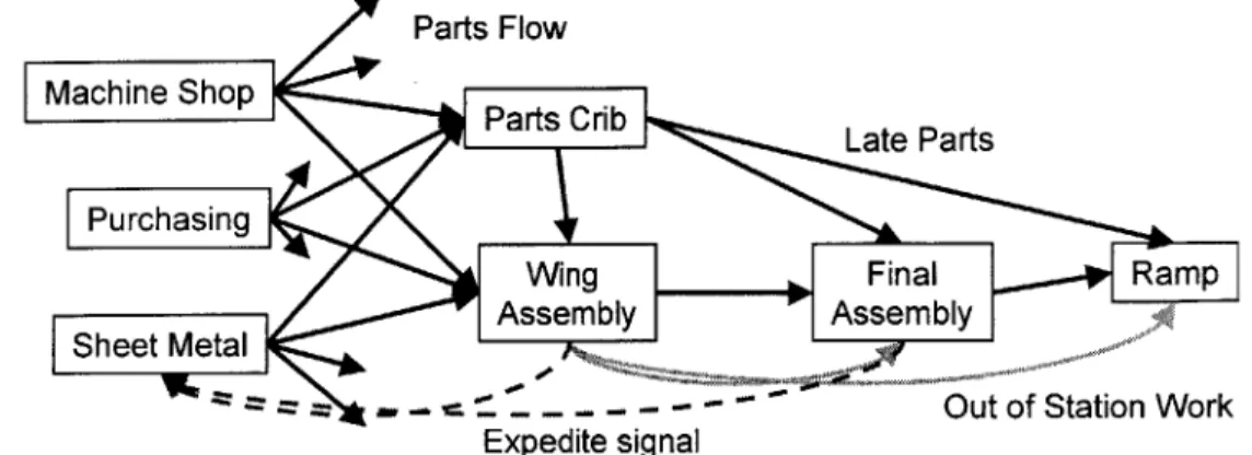
operator is also not available for the regular scheduled work. Figure 3 illustrates the flow of parts, out of station work, and expedite signals.
Parts Flow
Fcigure 3:p FParts Crib ate Parts
Purchasing
Wing 10 Final Ramp
Shet MtalAssemnbly- Assembly
- -. - '... - -Out of Station Work Expedite signal
Figure 3: Flow of parts, out of station work and expedite signals
3.3.5 Operator Work
In airframe assembly, operators perform a wide range of tasks. These tasks include loading parts into jigs and precision locating parts together, drilling, reaming, installing and removing temporary fasteners, deburring, fastening, and sealing on many different parts and assembly stages. This description applies mainly to the sheet metal workers; other workers also do electrical, hydraulic and plumbing installations. If the throughput time of a work center were one week, an operator would have a week's worth of different tasks to do. The same task then would be performed only once a week assuming the same operator performs the same task from unit to unit (not always the case).
3.3.6 Inspection/Quality
At certain points in the assembly process, the work must be inspected. The inspector examines the work and checks it off in a column of the work instructions or makes an entry into the data system. When all the tasks for a workstation are complete, the assembly requires a full "shake-down", which is an overall inspection, before it can proceed to the next station.
At the sites studied, designated inspectors always did the inspection. When an assembly is ready for inspection, the worker signs an inspection log or enters a call into the data system and an inspector is signaled to check the work. No systematic method for determining the
Wing Assembly Case Study
priority of jobs to be inspected when there is a queue was observed. At one site, the only parts that had priority were the sealing operations because the sealant should not be exposed to air and dust for too long. The work load on the inspectors varies greatly.
Non-Conformances
When a mistake is made during an assembly or when a quality issue is found by the inspector or the worker, it must be recorded and "reworked" to blueprint specifications. They are recorded as non-conformances and a non-conformance tag is written for each of them. An
engineering disposition is written for it and the rework is done.
Corrective Action
Corrective action (CA) is the root cause detection and prevention method. Since the non-conformance tags represent the production problems, they are analyzed to see if the cause of any of these problems may be eliminated. If so, a Corrective Action will be written and implemented. The time it takes to respond to a CA ranges from a few days to months depending on the complexity of the problem (tooling changes take longer). It is interesting to note that the quality engineers assigned to this task have performance measures based on the number of CA's completed and the size of the paperwork queues.
Rework
The most common types of quality issues that require rework are mis-drilled holes, short edge distances, elongated holes, set marks, gaps or other mistakes.
Shimming/Trimming operations
In airframe assembly, parts must be fitted together with very precise tolerances. Because of the large size of the parts, their compliance, thermal expansion and tolerance stack-ups, the parts have to be jig located [Whitney, 1996] and in some areas, shimming or trimming operations are required. These operations remove interferences or fill gaps during assembly.
Many instances of these procedures were observed as part of the planned assembly process. However, there was one instance observed where gaps were appearing between ribs and the brackets and unplanned shimming was necessary. This unplanned work caused much delay,