HAL Id: hal-01413449
https://hal.inria.fr/hal-01413449
Submitted on 9 Dec 2016
HAL is a multi-disciplinary open access archive for the deposit and dissemination of sci-entific research documents, whether they are pub-lished or not. The documents may come from teaching and research institutions in France or abroad, or from public or private research centers.
L’archive ouverte pluridisciplinaire HAL, est destinée au dépôt et à la diffusion de documents scientifiques de niveau recherche, publiés ou non, émanant des établissements d’enseignement et de recherche français ou étrangers, des laboratoires publics ou privés.
Approach
Emmanuelle Itam, Stephen Wornom, Bruno Koobus, Alain Dervieux
To cite this version:
Emmanuelle Itam, Stephen Wornom, Bruno Koobus, Alain Dervieux. A Volume-Agglomeration Multi-rate Time Advancing Approach. ECCOMAS Congress 2016 VII European Congress on Computational Methods in Applied Sciences and Engineering, Jun 2016, Hernissios, Crete, Greece. �hal-01413449�
Crete Island, Greece, 5–10 June 2016
A VOLUME-AGGLOMERATION MULTIRATE TIME ADVANCING
APPROACH
E. Itam1, S. Wornom2, B. Koobus1and A. Dervieux3 1IMAG, Universit´e de Montpellier, Montpellier, France
e-mail: {emmanuelle.itam,bruno.koobus}@umontpellier.fr
2 LEMMA, 2000 route des Lucioles, Sophia-Antipolis, France
3INRIA, 2204 route des Lucioles, Sophia-Antipolis, France
Keywords: computational fluid dynamics, multirate time advancing, explicit scheme, volume agglomeration, unstructured grid, hybrid turbulence model.
Abstract. A frequent configuration in computational fluid mechanics combines an explicit time advancing scheme for accuracy purposes and a computational grid with a very small portion of much smaller elements than in the remaining mesh. Examples of such situations are the traveling of a discontinuity followed by a moving mesh, and the large eddy simulation of high Reynolds number flows around bluff bodies where together very thin boundary layers and vortices of much more important size need to be captured. For such configurations, explicit time advancing schemes with global time stepping are very costly. In order to overcome this problem, the multirate time stepping approach represents an interesting improvement. The objective of such schemes, which allow to use different time steps in the computational domain, is to avoid penalizing the computational cost of the time advancement of unsteady solutions which can become large due to the use of small global time steps imposed by the smallest elements such as those constituting the boundary layers. In the present work, a new multirate scheme based on control volume agglomeration is proposed for the solution of the compressible Navier-Stokes equations possibly equipped with turbulence models. The method relies on a prediction step where large time steps are performed with an evaluation of the fluxes on macro-cells for the smaller elements for stability purpose, and on a correction step in which small time steps are employed only for the smaller elements. The efficiency of the proposed method is evaluated on several benchmarks flows: the problem of a moving contact discontinuity (inviscid flow), the computation with hybrid turbulence model of flows around bluff bodies like a tandem cylinders at Reynolds number1.66 × 105 , a circular cylinder at Reynolds number8.4 × 106, and a flow
1 INTRODUCTION
A frequent configuration in CFD calculations combines an explicit time advancing scheme for accuracy purpose and a computational grid with a very small portion of much smaller el-ements than in the remaining mesh. Examples of such situations are isolated traveling shock and large eddy simulation of high Reynolds number flows around bluff bodies where very thin boundary layers and vortices of much more important size need to be captured.
For such configurations, explicit time advancing schemes with global time stepping are very costly. In order to overcome this problem, the multirate time stepping approach represents an interesting alternative. By using several different timestep sizes on different subdomains, multirate timestepping avoids to apply too small timesteps in regions where the mesh is rather coarser. Then it avoids to use the small timesteps of boundary layer on the whole domain and thus penalize the global computational cost of the advancement in time of unsteady solutions. Many works have been published on multirate methods in the field of ODE, see for example [1, 2, 3, 4, 5, 6, 7, 8, 9, 10, 11, 12], but only few works were conducted on multirate time advancing schemes for the solution of PDE and hyperbolic conservation laws [13, 14, 15, 16, 18, 17], and rare applications were performed in Computational Fluid Dynamics (CFD), for shock propagation in [17] and for shallow water computations in [18, 19]. Therefore, there is still much work to do to provide a viable multirate method for CFD applications. In this work, we propose a new multirate scheme based on control volume agglomeration which is well suited to our numerical framework using a mixed finite volume/finite element formulation. The method relies on a prediction step where large time steps are used with an evaluation of the fluxes performed on the macro-cells for the smaller elements, and on a correction step in which small time steps are employed only for the smaller elements. Target applications are three-dimensional unsteady flows modeled by the compressible Navier-Stokes equations equipped with turbulence models and discretized on unstructured possibly deformable meshes.
2 Multirate time advancing by volume agglomeration
In this section, we present a multirate time advancing scheme based on volume agglomera-tion which is currently being developed for the soluagglomera-tion of the three-dimensional compressible Navier-Stokes equations. The finite-volume spatial discretization combined with an explicit forward-Euler time-advancing is written:
voli win+1= voliwni + Ψi, ∀ i = 1, ..., ncell,
where voliis the volume of celli, wni = (ρni, (ρu)ni, (ρv)ni, (ρw)ni, Ein, (ρk)ni, (ρε)ni) are as
usu-ally the density, moments, total energy, turbulent energy and turbulent dissipation at celli and
time level tn, and ncell the total number of cells in the mesh.
We assume that we can define a maximal stable time step (local timestep) ∆ti, i = 1, ..., ncell
on each node. This can be based on a stability analysis which in practice takes into account ad-vective terms (condition of Courant-Friedrichs-Lewy or CFL) and diffusive terms of the discrete PDE under study, together with the type of explicit time advancing scheme. In short, using ∆ti
is advancing at CF L = 1. A consistent time advancing should use for stability a global time step∆t = min1,ncell ∆ti. The user is supposed to choose a (integer) timestep factor K > 1.
We first define the inner zone and the outer zone, the coarse grid, and the construction of the fluxes on the coarse grid, ingredients on which our multirate time advancing scheme is based.
• Definition of the Inner and Outer zones :
– We define the outer zone as the set of cells i for which the explicit scheme is stable for a time step K∆t
∆ti ≥ K∆t,
– the inner zone is the set of cells for which
∆ti < K∆t.
• Definition of the coarse grid : – Objective :
∗ Advancement in time is performed with time step K∆t
∗ Advancement in time preserves accuracy in the outer zone (space order of 3, Runge-Kutta 4)
∗ Advancement in time is consistent in the inner zone
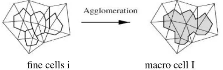
– A coarse grid is defined on the inner zone by applying cell agglomeration in such a way that on each macro-cell, the maximal local time step is at least K∆t. Ag-glomeration consists in considering each cell and aggregating to it neigboring cells which are not yet aggregated to an other one (Figure 1). Agglomeration into macro cell is re-iterated until macro-cells with maximal timestep smaller then K∆t have disappeared.
– Time-advancing on the macro-cells :
∗ We advance in time the chosen explicit scheme (Runge-Kutta 4 in our exam-ples) on the coarse grid with K∆t as time step
∗ A flux smoothing can be performed on the macro cells for stability purpose.
• Construction of the flux on the coarse grid
– The nodal fluxes Ψiare assembled on the fine cells (as usual)
– Fluxes are summed on the macro-cells I (inner zone) :
ΨI =X
k∈I
Ψk (1)
– Possibly smoothing of the coarse flux (inner zone) :
ΨI = ( X
K∈V(I)
ΨKvolK)/( X
K∈V(I)
fine cells i macro cell I
Figure 1: Sketch (in 2D) of the agglomeration of 4 cells into a macro-cell. Cells are dual cells of triangles, bounded by sections of triangle medians.
The multirate algorithm is then based on a prediction step and a correction step as defined hereafter :
Step 1 (prediction step) :
The solution is advanced in time with time step K∆t, on the macro cells in the inner zone and on the fine cells in the outer zone :
For α = 1, RKstep
outer zone : voliw (α) i = voliw (0) i + bαK∆t Ψ (α−1) i (3)
inner zone : volIwI,(α) = volIwI,(0) + bαK∆t ΨI,(α−1) (4)
wi(α) = wI,(α) for i ∈ I (5)
EndFor α.
Step 2 (correction step) :
• The unknowns are frozen in the outer zone at level tn+ K∆t.
• The outer unknowns near the boundary of the outer zone which are necessary for advanc-ing the inner zone are interpolated in time.
• In the inner zone, using these interpolated values, the solution is advanced in time with the chosen explicit scheme and time step ∆t.
Remark: The complexity, proportional to the number of points in the inner zone, is therefore mastered.
3 Applications
The multirate algorithm introduced in the previous section was implemented in the parallel CFD code AIRONUM shared by INRIA Sophia-Antipolis, LEMMA company and University of Montpellier. The parallelism relies on mesh partitioning and MPI. A description of this tool, which solves with a mixed element/volume method on unstructured meshes the compressible Euler and Navier-Stokes equations possibly equipped with a turbulence model, can be found in [20] and [21]. When computing hybrid RANS-LES flows, an important part of the mesh is dedicated to the boundary layer and involved possibly very small cells. Another important part of the mesh is dedicated to the capture of vortices with many cells of medium size (possibly 10-100 larger than smaller cells of the boundary layers). In introducing the multirate algorithm, attention was paid to several issues related to parallelism, and in particular a macro-cell belongs to only one subdomain of the partition, and we have optimized the evaluation of the fluxes on the macro-cells located at the boundary between neighboring subdomains. However, in the present phase of the study, no optimization of the MPI partitions for balancing the load in the inner zone has been done.
3.1 Contact discontinuity
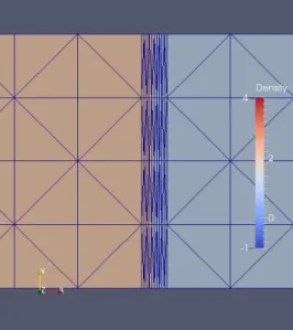
In this first example, we consider the case of a moving contact discontinuity. For this pur-pose, the compressible Euler equations are solved in a rectangular parallelepiped as compu-tational domain where the density is initially discontinuous at its middle (see Figure 2) while moments and pressure are uniform.
Figure 2: ALE calculation of a traveling contact discontinuity. Instantaneous mesh with mesh concentration in the middle of zoom and corresponding advected discontinuous fluid density.
The uniform velocity is a purely horizontal one. As can be seen in Figure 2, small cells are present on either side of the disconstinuity. The mesh moves during the computation in such a way that the nodes located at the discontinuity are still the same, and that the number of small cells are equally balanced on either side of the discontinuity. An Arbitrary Lagrangian-Eulerian formulation is then used to solve the Euler equations on the resulting deforming mesh. Our long term objective is to combine the multirate time advancing with a mesh adaptation algorithm in such a way that the small time steps imposed by the necessary good resolution of
the discontinuity remain of weak impact on the global computational time.
The mesh used in this simulation contains 25000 nodes and 96000 tetrahedra. The compu-tational domain is decomposed into 2 subdomains. When integer K, used for the definition of the inner and outer zones, is set to 5, 10 and 15, the percentage of nodes located in the inner zone is always 1.3%, which corresponds to the vertices of the small cells located on either side of the discontinuity.
The multirate scheme with the aforementioned values of K, as well as a 4-stage Runge-Kutta method, are used for the computation. Each simulation was run over an elapsed time of 10 minutes, and 2 cores were used on a Bullx B720 cluster. This elapsed time corresponds to 2390 time steps for the explicit scheme, and 268, 365 and 536 times steps for K equals 15, 10 and 5, respectively. An improvement in the efficiency of about 1.75, 1.58 and 1.15 is observed when K is set to 15, 10 and 5, respectively.
3.2 Tandem cylinders
Our main study concerning the application of multirate is the calculation of a flow around a tandem cylinders at Reynolds number 1.66 × 10⁵. This was a test case of an AIAA work-shop, see [22]. It is a challenging computation since several complex flow features need to be captured around multiple bodies (stagnation zones, boundary layers, shear layers, separations, laminar-turbulent transition, recirculations, vortex sheddings, wakes). Furthermore, small cells are necessary for a proper prediction of the very thin boundary layers, which implies very small global time steps so that classical explicit calculations become very costly. The application of our multirate scheme to the tandem cylinders benchmark is also made more difficult by the fact that we use a hybrid turbulence model based on RANS and VMS-LES approaches, so that additional equations associated with turbulent variables need to be advanced in time.
In order to illustrate the quality of resolution, the Q-criterion isosurfaces are shown in Figure 3. It shows the complex flow features and the very small structures that need to be captured by the numerical model and the turbulence model, which renders this simulation particularly chal-lenging. Further information concerning the comparison between computation and experiments are available in [21].
Two meshes were used for this study : a coarse mesh which contains 2.6 million nodes and 15 million tetrahedra, and a fine mesh with 16 million nodes and 96 million tetraedra. For both the smallest cell thickness is 1.2.10−4.
• Coarse mesh
The computational domain is decomposed into 192 subdomains. When integer K, used for the definition of the inner and outer zones, is set to 2, 5 and 10, the percentage of nodes located in the inner zone is 4%, 16% and 25%, respectively.
The lift curve obtained by the multirate scheme with K = 10 and the explicit scheme cor-responding to half of a period of vortex shedding for the first cylinder is given in Figure 4. The underlying explicit scheme is the 4-stage Runge-Kutta method and the CFL number was set to 1. Each simulation was left running over an elapsed time of 40 hours. A num-ber of 192 cores on a Bullx B720 cluster was used to perform these computations. One can check that the responses given by the two schemes are close to each other, except for the oscillations at the top of the lift curve for the multirate method that are an unproperly controlled restart in the simulation. The number of time steps is 15284 for the multirate
Figure 3: Tandem cylinders at Reynolds number 1.66 × 10⁵: instantaneous Q-criterion isosurfaces (coloured with
velocity modulus).
scheme and 132531 for the classical explicit scheme. From Figure 4, an improvement in the efficiency of about 1.14 is observed when the multirate scheme is used in our paral-lel solver. This rather slight improvement in efficiency can be explained by the fact that some of the subdomains almost contain only inner nodes so that workload is not equally shared by each computer core when the proposed multirate approach is used. Indeed, in our parallel strategy which is based on a decomposition of the computational domain in subdomains, designed to minimize the inter-core communications, and on a message passing parallel programming (MPI) model, each subdomain is assigned to a computer core. It is clear that in order to further increase the efficiency of the multirate approach in our parallel computing framework, the domain decomposition needs to be adapted. Based on the fact that the cost per node in these explicit simulations is essentially due to the computation of the convective and diffusive fluxes, we can deduce that, for the multirate simulation that was performed and which involves K = 10 and 25% of the nodes located in the inner zone, the benefit-cost ratio between the multirate scheme and the classical 4-stage Runge-Kutta method would be 3 from a sequential computation. In a second step, the multirate simulation is carried out with K = 5 for the same bench-mark, which means that the RK4 scheme is now performed with time steps 5∆t and ∆t for the nodes located in the outer zone and the nodes located in the inner zone, respec-tively. The lift curve obtained by the multirate scheme with K = 5 and K = 10 for the first cylinder is depicted in Figure 5. Both simulations were left running over an elapsed time of 20 hours, which allows to simulate a quarter of a period of vortex shedding with a CFL number set to 1. One can notice that the response is similar, as expected, for both values of K, and that the efficiency is improved by a factor 1.09 when the multirate scheme is used with K = 10 in our parallel solver. From a sequential point of view, we can also deduce that the cost of the multirate scheme with K = 5 and K = 10 would be
300 350 400 450 500 550 600 650 700 750 800 0.91 0.915 0.92 0.925 0.93 0.935 0.94 0.945 0.95 0.955 0.96 Lift Time lift-multirate-K10-CFL1.data lift-explicit-CFL1.data
Figure 4: Coarse mesh - Tandem cylinders at Reynolds number 1.66×10⁵: lift curve for the first cylinder, multirate
scheme (K=10) and explicit RK4 scheme, corresponding to an elapsed time of 40 hours.
of the same order.
300 350 400 450 500 550 600 650 700 750 800 0.91 0.915 0.92 0.925 0.93 0.935 0.94 Lift Time lift-multirate-K5-CFL1.data lift-multirate-K10-CFL1.data
Figure 5: Coarse mesh - Tandem cylinders at Reynolds number 1.66×10⁵: lift curve for the first cylinder, multirate scheme with K=5 and K=10, corresponding to an elapsed time of 20 hours.
• Fine mesh:
The computational domain is decomposed into 768 subdomains. When integer K, used for the definition of the inner and outer zones, is set to 5, 10 and 20, the percentage of nodes located in the inner zone is 18%, 24% and 35%, respectively.
The lift curve obtained by the multirate scheme with K = 5, K = 10, and K = 20, and by the explicit scheme, is shown in Figure 6. The underlying explicit scheme is the 4-stage
Runge-Kutta method and the CFL number was set to 1. Each simulation was left running over an elapsed time of 1 hour. A number of 768 cores on the Bullx cluster was used to perform these computations.
Figure 6: Fine mesh - Tandem cylinders at Reynolds number 1.66 × 10⁵: lift curve for the first cylinder, multirate scheme (K = 5, K = 10, K = 20) and explicit RK4 scheme, corresponding to an elapsed time of 1 hour.
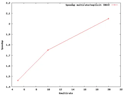
One can observe that the lift curves quickly become different between the various options because of differences in the time step size and the rapidly fluctuating small scales that can be captured by this fine mesh. These differences affect the instantaneous solution but do not notably affect the flow statistics. From this Figure, an improvement in the efficiency of a factor slightly greater than 2 is observed when the multirate option is used with K = 20 compared to the classical 4-stage Runge-Kutta explicit scheme. For K = 5 and K = 10 this improvement becomes 1.5 and 1.8, respectively (see Figure 7). The better efficiency observed with the fine mesh compared to the coarse mesh is certainly due to a better distribution of the workload among the cores when the multirate approach is used.
As for the coarse mesh, the benefit-cost ratio between the multirate scheme and the classical 4-stage Runge-Kutta method would be 3 from a sequential point of view.
3.3 Circular cylinder
The third application concerns the simulation of the flow around a circular cylinder at Reynolds number 8.4 × 10⁶. As for the previous benchmark, the computational domain is made of small cells around the body in order to allow a proper representation of the very thin boundary layer that occurs at such a high Reynolds number. On the other hand, the same hybrid RANS/VMS-LES model as that of the previous benchmark is used to compute this flow, which implies again that both the fluid and turbulent variables need to be advanced by the time integration scheme, and therefore also the multirate method.
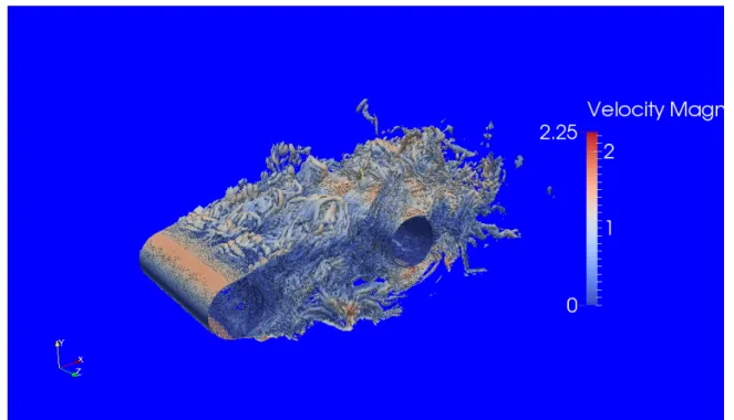
Figure 8 depicts the Q-criterion isosurfaces and shows the very small and complex struc-tures that need to be captured by the numerical and the turbulence models, which renders this simulation very challenging.
Figure 7: Fine mesh - Tandem cylinders at Reynolds number 1.66 × 10⁵: speedup multirate/explicit (RK4).
The mesh used in this simulation contains 4.3 million nodes and 25 million tetrahedra. The smallest cell thickness is 2.5.10−6. The computational domain is decomposed into 768 subdo-mains. When integer K, used for the definition of the inner and outer zones, is set to 5, 10 and 20, the percentage of nodes located in the inner zone is 15%, 19% and 24%, respectively.
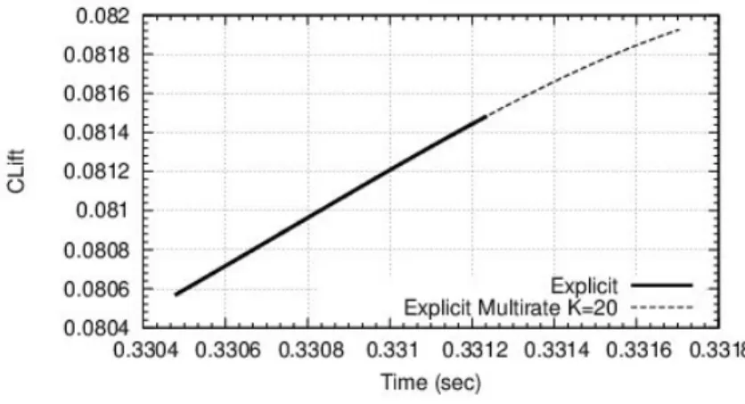
The lift curve corresponding to the explicit scheme and the multirate option with K = 20 is shown in Figure 9. The explicit scheme is the 4-stage Runge-Kutta method. Each simulation was left running over an elapsed time of 20 minutes, and 768 cores were used on a Bullx B720 cluster. The number of time steps is 175 for the multirate scheme and 2153 for the explicit method. From Figure 9, we deduce an improvement in the efficiency of about 1.62 when the multirate scheme is used with K = 20, as compared with 3 which would be, from a sequential point of view, the ideal benefit-cost ratio between the multirate scheme, with K = 20 and 24% of the nodes located in the inner zone, and the explicit scheme. This result in efficiency is pretty good, considering the fact that the domain decomposition does not equally share the number of inner nodes between the subdomains, as noticed in the previous section.
The multirate simulation was also carried out for K = 5 and K = 10, which means that the time step ratio between the outer zone and the inner zone is 5 and 10, respectively. The efficiency is then improved by a factor 1.25 (K = 5), 1.46 (K = 10) and 1.62 for K = 20. 3.4 Spatial probe
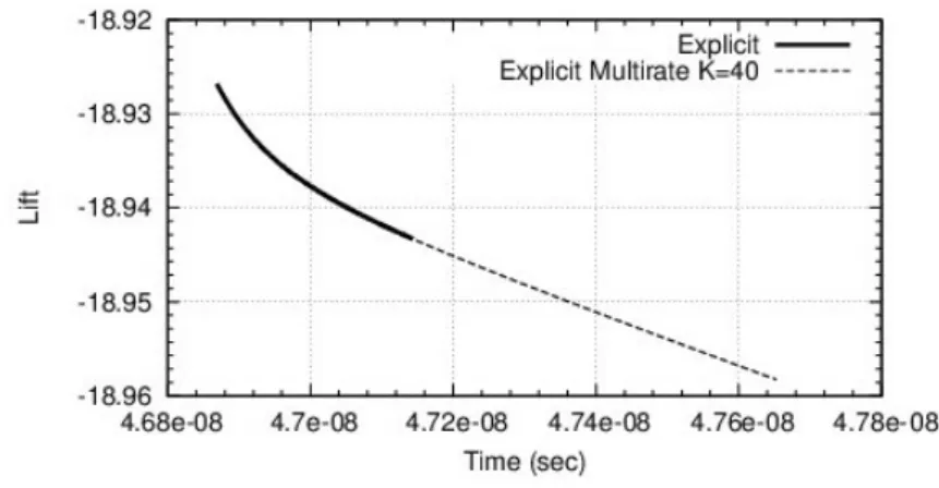
The last case is the supersonic flow around a probe model for Exomars (see for example [23]). We choose a Reynolds number of 1 million. Delicate features in this simulation are a separation arising on a highly curved wall and relatively large recirculation zone at afterbody. Hybrid RANS-LES calculation brings more information than pure RANS does. The mesh involves 4, 380000 cells and the smallest mesh thickness is 2.10−5. A sketch of this flow is presented in Figure 10. The impact of multirate on accuracy is very low (Figure 11). The gain in efficiency varies from 2.18 with K = 10 and 56 cells in the inner zone to a maximum of 2.89 with K = 40 and 151 cells in the inner zone. For K = 40, only 15 subdomains have inner cells (mean number 15 inner cells).
Figure 8: Circular cylinder at Reynolds number 8.4 × 10⁶: instantaneous Q-criterion isosurfaces (coloured with velocity modulus).
Figure 9: Circular cylinder at Reynolds number 8.4 × 10⁶: comparison of lift coefficient curves for explicit (bold
line) and multirate (dashes) .
4 Conclusion
A new multirate strategy is proposed in this work. The method is based on control volume agglomeration, and relies on a prediction step where large time steps are used and where the fluxes for the smaller elements are evaluated on macro cells for stability purpose. A correction step follows in which only the smaller elements are advanced in time with a small time step. Preliminary results are given. They show that the proposed multirate strategy can be applied in complex CFD problems such as the prediction of three-dimensional flows around bluff bodies with complex hybrid turbulence models. Nevertheless, there is still work to do to obtain an
Figure 10: Flow around a probe model at Reynolds number 1 million. Q criterion.
Figure 11: Flow around a probe model at Reynolds number 1 million. Impact of multirate on instantaneous lift accuracy.
efficient multirate method in a parallel numerical framework. Indeed, at the present time, the domain decomposition into subdomains is designed to minimize the inter-core communications. We need to adapt the domain decomposition in such a way that the workload becomes shared equally for both Step1 and Step2 of the multirate.
Acknowledgments
This work has been supported by French National Research Agency (ANR) through “Mod`ele num´erique” program (projet MAIDESC n0ANR-13-MONU-0010).
HPC resources from GENCI-[CINES] (Grant 2014-c20142a5067 and 2014-x20142a6386) are also gratefully acknowledged.
REFERENCES
[1] J. R. Rice, Split Runge-Kutta Method for Simultaneous Equations, Journal of Research of the National Bureau of Standards - B. Mathematics and Mathematical Physics, Vol. 64B, No3, 1960.
[2] J.F. Andrus, Numerical solution of systems of ordinary differential equations separated into subsystems, SIAM J. Numerical Analysis, Vol.16, No 4, 1979.
[3] C.W. Gear and D.R. Wells, Multirate linear multistep methods, BIT, 484-502, 1984. [4] S. Skelboe, Stability properties of backward differentiation multirate formulas, Applied
Numerical Mathematics, 5, 151-160, 1989.
[5] J. Sand and S. Skelboe, Stability of backward Euler multirate methods and convergence of waveform relaxation, BIT, 32, 350-366, 1992.
[6] J.F. Andrus, Stability of a multi-rate method for numerical integration of ODE’S, Com-puters Math. Applic., Vol. 25, No 2, pp. 3-14, 1993.
[7] M. G¨unther and P. Rentrop, Multirate ROW methods and latency of electric circuits, Ap-plied Numarical Mathematics, 13, 83-102, 1993.
[8] C. Engstler and C. Lubich, MUR8: a multirate extension of the eight-order Dormer-Prince method, Applied Numerical Mathematics, 25, 185-192, 1997.
[9] C. Engstler and C. Lubich, Multirate Extrapolation Methods for Differential Equations with Different Time Scales, Computing, 58, 173-185, 1997.
[10] M. G¨unther, A. Kvaerno and P. Rentrop, MultA. Guelhan, J. Klevanski and S. Willems,irate partitioned Runge-Kutta methods, BIT, Vol. 38, No 2, pp. 101-104, 1998. [11] M. G¨unther, A. Kvaerno and P. Rentrop, Multirate partitioned Runge-Kutta methods, BIT,
Vol. 41, No 3, pp. 504-514, 2001.
[12] V. Savcenco, W. Hundsdorfer and J.G. Verwer, A multirate time stepping strategy for stiff ordinary differential equations, BIT, Vol. 47, pp. 137-155, 2007.
[13] E. Constantinescu and A. Sandu, Multirate Timestepping Methods for Hyperbolic Con-servation Laws, J. sci. Comp, 33(3), 239-278, 2007.
[14] A. Sandu and E. Constantinescu, Multirate Explicit Adams Methods for Time Integration of Conservation Laws, J. Sci. Comp, 38: 229-249, 2009.
[15] P.R. Mugg, Construction and analysis of multi-rate partitioned Runge-Kutta methods, The-sis, Naval Postgraduate School, Monterey, California, June 2012.
[16] R. Kirby, On the convergence of high resolutin methods with multiple time scales for hyperbolic laws, Mathematics of Computation, Vol. 72, Number 243, 129-1250, 2002. [17] R. L¨ohner, K. Morgan and O.C. Zienkiewicz, The use of domain splitting with an explicit
[18] B. Seny, J. Lambrechts, T. Toulorge, V. Legat, J.-F. Remacle, An efficient parallel imple-mentation of explicit multirate Runge-Kutta schemes for discontinuous Galerkin compu-tations, J. of Comp. Phys., Vol. 256, pp. 135-160, 2014.
[19] B. Seny, J. Lambrechts, V. Legat, J.-F. Remacle, YIC2013, Second ECCOMAS Young Investigators Conference 2 6 September 2013, Bordeaux, France.
[20] C. Moussaed, M.V. Salvetti, S. Wornom, B. Koobus and A. Dervieux, “Simulation of the flow past a circular cylinder in the supercritical regime by blending RANS and variational-multiscale LES models”, Journal of Fluids and Structures, Volume 47, May 2014, pages 114-123.
[21] E. Itam, S. Wornom, B. Koobus, B. Sainte-Rose, A. Dervieux, Simulation of multiple blunt-body flows with a hybrid variational multiscale model, Conference on Modelling Fluid Flow (CMFF 15) The 16th International Conference on Fluid Flow Technologies Budapest, Hungary, September 1-4, 2015
[22] D. Lockard, Summary of the Tandem Cylinder Solutions from the Benchmark Problems for Airframe Noise Computations-I, Proceedings of Workshop AIAA-2011-353 (2011). [23] A. Guelhan, J. Klevanski and S. Willems, Experimental Study of the Dynamic Stability
of the Exomars Capsule. In: Proceedings of 7th European Symposium on Aerothermody-namics. ESA Communications. 7th European Symposium on Aerothermodynamics, 9.-12. Mai 2011, Brugge, Belgium (2011).