https://doi.org/10.4224/23000318
READ THESE TERMS AND CONDITIONS CAREFULLY BEFORE USING THIS WEBSITE.
https://nrc-publications.canada.ca/eng/copyright
Vous avez des questions? Nous pouvons vous aider. Pour communiquer directement avec un auteur, consultez la
première page de la revue dans laquelle son article a été publié afin de trouver ses coordonnées. Si vous n’arrivez pas à les repérer, communiquez avec nous à PublicationsArchive-ArchivesPublications@nrc-cnrc.gc.ca.
Questions? Contact the NRC Publications Archive team at
PublicationsArchive-ArchivesPublications@nrc-cnrc.gc.ca. If you wish to email the authors directly, please see the first page of the publication for their contact information.
NRC Publications Archive
Archives des publications du CNRC
For the publisher’s version, please access the DOI link below./ Pour consulter la version de l’éditeur, utilisez le lien DOI ci-dessous.
Access and use of this website and the material on it are subject to the Terms and Conditions set forth at
Rolling contact fatigue: a comprehensive review Magel, Eric E.
https://publications-cnrc.canada.ca/fra/droits
L’accès à ce site Web et l’utilisation de son contenu sont assujettis aux conditions présentées dans le site
LISEZ CES CONDITIONS ATTENTIVEMENT AVANT D’UTILISER CE SITE WEB.
NRC Publications Record / Notice d'Archives des publications de CNRC: https://nrc-publications.canada.ca/eng/view/object/?id=2629e321-fe89-4eda-8531-662d35dbca8a https://publications-cnrc.canada.ca/fra/voir/objet/?id=2629e321-fe89-4eda-8531-662d35dbca8a
U.S. Department of Transportation
Federal Railroad Administration
Rolling Contact Fatigue: A Comprehensive Review
Office of Railroad Policy and Development Washington, DC 20590
NOTICE
This document is disseminated under the sponsorship of the Department of Transportation in the interest of information exchange. The United States Government assumes no liability for its contents or use thereof. Any opinions, findings and conclusions, or recommendations expressed in this material do not necessarily reflect the views or policies of the United States Government, nor does mention of trade names, commercial products, or organizations imply endorsement by the United States Government. The United States Government assumes no liability for the content or use of the material contained in this document.
NOTICE
The United States Government does not endorse products or manufacturers. Trade or manufacturers‘ names appear herein solely because they are considered essential to the objective of this report.
REPORT DOCUMENTATION PAGE
Form Approved OMB No. 0704-0188Public reporting burden for this collection of information is estimated to average 1 hour per response, including the time for reviewing instructions, searching existing data sources, gathering and maintaining the data needed, and completing and reviewing the collection of information. Send comments regarding this burden estimate or any other aspect of this collection of information, including suggestions for reducing this burden, to Washington Headquarters Services, Directorate for Information Operations and Reports, 1215 Jefferson Davis Highway, Suite 1204, Arlington, VA 22202-4302, and to the Office of Management and Budget, Paperwork Reduction Project (0704-0188), Washington, DC 20503. 1. AGENCY USE ONLY (Leave blank) 2. REPORT DATE
November 2011
3. REPORT TYPE AND DATES COVERED
Technical Report
4. TITLE AND SUBTITLE
Rolling Contact Fatigue: A Comprehensive Review
5. FUNDING NUMBERS
DTFR53-05-H-00203
6. AUTHOR(S)
Eric E. Magel
7. PERFORMING ORGANIZATION NAME(S) AND ADDRESS(ES)
Centre for Surface Technology
2320 Lester Road, Ottawa, Ontario K1V 1S2, Canada
8. PERFORMING ORGANIZATION REPORT NUMBER
9. SPONSORING/MONITORING AGENCY NAME(S) AND ADDRESS(ES)
U.S. Department of Transportation Federal Railroad Administration
Office of Railroad Policy and Development Washington, DC 20590
10. SPONSORING/MONITORING AGENCY REPORT NUMBER
DOT/FRA/ORD-11/24
11. SUPPLEMENTARY NOTES
Program Manager: Ali Tajaddini
12a. DISTRIBUTION/AVAILABILITY STATEMENT
This document is available to the public through the FRA Web site at http://www.fra.dot.gov.
12b. DISTRIBUTION CODE
13. ABSTRACT (Maximum 200 words)
Rolling contact fatigue (RCF) is a pervasive and insidious problem on all types of railway systems. Although it is a dominant cause of maintenance and replacements on heavy haul rail lines, it is also a significant economic and safety challenge for
commuter and metro lines. It is a subject of intense research around the globe, with strong academic research being undertaken in Europe particularly, with more practical work being performed in Australia, South Africa, and North America. The safety implications of RCF include being responsible for about 100 FRA reportable derailments annually in North America. The poster child for hazardous RCF is the Hatfield derailment in the United Kingdom, which incurred four deaths, 39 injuries, and economic fallout easily exceeding GBP1 billion, dismemberment of the railway authority and manslaughter charges against several railway officials. The economic implications of RCF to the North America railway industry for rail replacement alone amounts to over USD300 million annually, with costs of inspection and derailments, as well as damage to track and rolling stock, and derailment costs further increasing that number. Of the USD100+ million dollars spent annually on rail grinding in North America, at least ≥30 percent can be attributed to RCF. A review of the types or RCF defects on wheels and rails, causal mechanisms and monitoring and maintenance practices has been undertaken for the purpose of identifying gaps and the most pressing areas for research and development.
14. SUBJECT TERMS
Rolling contact fatigue, RCF, rail gauge corner cracking, wheel tread cracking, monitoring RCF, RCF damage model, friction management, rail grinding
15. NUMBER OF PAGES 132 16. PRICE CODE 17. SECURITY CLASSIFICATION OF REPORT Unclassified 18. SECURITY CLASSIFICATION OF THIS PAGE Unclassified 19. SECURITY CLASSIFICATION OF ABSTRACT Unclassified 20. LIMITATION OF ABSTRACT
METRIC/ENGLISH CONVERSION FACTORS
ENGLISH TO METRIC
METRIC TO ENGLISH
LENGTH (APPROXIMATE) LENGTH (APPROXIMATE)
1 inch (in) = 2.5 centimeters (cm) 1 millimeter (mm) = 0.04 inch (in) 1 foot (ft) = 30 centimeters (cm) 1 centimeter (cm) = 0.4 inch (in) 1 yard (yd) = 0.9 meter (m) 1 meter (m) = 3.3 feet (ft)
1 mile (mi) = 1.6 kilometers (km) 1 meter (m) = 1.1 yards (yd) 1 kilometer (km) = 0.6 mile (mi)
AREA (APPROXIMATE) AREA (APPROXIMATE)
1 square inch (sq in, in2) = 6.5 square centimeters (cm2) 1 square centimeter (cm2) = 0.16 square inch (sq in, in2) 1 square foot (sq ft, ft2) = 0.09 square meter (m2) 1 square meter (m2) = 1.2 square yards (sq yd, yd2) 1 square yard (sq yd, yd2
) = 0.8 square meter (m2
) 1 square kilometer (km2
) = 0.4 square mile (sq mi, mi2
) 1 square mile (sq mi, mi2
) = 2.6 square kilometers (km2
) 10,000 square meters (m2
) = 1 hectare (ha) = 2.5 acres 1 acre = 0.4 hectare (he) = 4,000 square meters (m2)
MASS - WEIGHT (APPROXIMATE) MASS - WEIGHT (APPROXIMATE)
1 ounce (oz) = 28 grams (gm) 1 gram (gm) = 0.036 ounce (oz) 1 pound (lb) = 0.45 kilogram (kg) 1 kilogram (kg) = 2.2 pounds (lb) 1 short ton = 2,000 pounds
(lb)
= 0.9 tonne (t) 1 tonne (t) =
=
1,000 kilograms (kg) 1.1 short tons
VOLUME (APPROXIMATE) VOLUME (APPROXIMATE)
1 teaspoon (tsp) = 5 milliliters (ml) 1 milliliter (ml) = 0.03 fluid ounce (fl oz) 1 tablespoon (tbsp) = 15 milliliters (ml) 1 liter (l) = 2.1 pints (pt)
1 fluid ounce (fl oz) = 30 milliliters (ml) 1 liter (l) = 1.06 quarts (qt) 1 cup (c) = 0.24 liter (l) 1 liter (l) = 0.26 gallon (gal)
1 pint (pt) = 0.47 liter (l)
1 quart (qt) = 0.96 liter (l)
1 gallon (gal) = 3.8 liters (l)
1 cubic foot (cu ft, ft3) = 0.03 cubic meter (m3) 1 cubic meter (m3) = 36 cubic feet (cu ft, ft3) 1 cubic yard (cu yd, yd3
) = 0.76 cubic meter (m3
) 1 cubic meter (m3
) = 1.3 cubic yards (cu yd, yd3
)
TEMPERATURE (EXACT) TEMPERATURE (EXACT)
[(x-32)(5/9)] °F = y °C [(9/5) y + 32] °C = x °F
QUICK INCH - CENTIMETER LENGTH CONVERSION
1
0 2 3 4 5
Inches
Centimeters0 1 2 3 4 5 6 7 8 9 10 11 12 13
QUICK FAHRENHEIT - CELSIUS TEMPERATURE CONVERSION
-40° -22° -4° 14° 32° 50° 68° 86° 104° 122° 140° 158° 176° 194° 212°
°F
°C-40° -30° -20° -10° 0° 10° 20° 30° 40° 50° 60° 70° 80° 90° 100°
For more exact and or other conversion factors, see NIST Miscellaneous Publication 286, Units of Weights and
Acknowledgments
The author is extremely grateful to the U.S. Federal Railroad Administration for its financial support of this review through grant DTFR-53-05-H-00203-mod-4.
The author would next like to recognize the assistance of many colleagues during the production of this report who supplied technical information, photographs, various supplementary
information and cross references. Thanks are due to the following individuals, listed in alphabetical order:
Chris Barkan (University of Illinois, Urbana-Champaign, IL), Bill Bell (CSX, Jacksonville, FL), Li Cheng (Salient Systems, Austin, TX), Mathew Dick (ENSCO, Falls Church, VA), Marty Gearhart (Union Pacific, Omaha, NE), Stuart Grassie (Loram, Germany), Martin Hiensch (DeltaRail, The Netherlands), Cory Hogan (Transportation Technology Center, Inc. (TTCI), Pueblo, CO), Jude Igwemezie (Applied Rail Research Technologies, Toronto, Canada), Makoto Ishida (Railway Technical Research Institute, Tokyo, Japan), Joe Kalousek ([retired] National Research Council Canada), Tyler Kerr (Canadian Pacific Railway, Calgary, Alberta, Canada), Jean Kneale (NRC Canada), Yan Liu (NRC Canada), Francisco Robles-Hernandez (University of Houston, Houston, TX), Michael Roney (Canadian Pacific Railway), Ken Rownd (TTCI), Wolfgang Schoech (Speno, Geneva, Switzerland), Peter Sroba (Sroba Rail Services, Australia), Daniel Szablewski (TTCI), Harry Tournay (TTCI), and Allan Zarembski (Zeta-Tech, Cherry Hill, NJ).
Special thanks are extended to Daniel Stone of Hunter Holiday Consulting (Pueblo, CO) and Kevin Sawley of Interfleet (Derbyshire, U.K.), who, more than any others, entertained numerous queries and graciously accepted and responded to or passed along questions related to rail and wheel metallurgy and performance.
Contents
Executive Summary ... 1
1 RCF of Wheels and Rails ... 5
1.1 The International Scope ... 5
1.2 Safety Implications of RCF ... 8
1.2.1 (Rail) Ultrasonic No-Tests ...8
1.3 Types of RCF Defects ... 9
1.3.1 Rail Gauge Corner Cracking ...9
1.3.2 Wheel Tread Cracking ...12
1.3.3 Rail and Wheel Shelling ...12
1.3.4 Rail Transverse Defects ...16
1.3.5 (Rail) Squats ...18
1.3.6 (Rail) Crushed Heads ...19
1.3.7 (Wheel) Spalling ...20
1.3.8 (Wheel) Shattered Rim ...21
1.3.9 (Wheel) Vertical Spit Rim ...22
1.4 Economic Implications of RCF ... 23
2 Formation of RCF ... 25
2.1 Crack Initiation ... 26
2.1.1 Surface Crack Initiation in Rails ...26
2.1.2 Subsurface Crack Initiation ...29
2.1.3 Contact Stress ...32
2.1.4 Traction ...33
2.1.5 Material Strength ...34
2.1.6 Thermal Softening ...35
2.1.7 Material Embrittlement ...36
2.1.8 Models of Crack Initiation ...37
2.2 Crack Propagation ... 38
2.2.1 Shear Strength ...40
2.2.2 Strain Rate Dependence ...41
2.2.3 Contact Stresses ...42
2.2.4 Moisture and Grease ...45
2.2.5 Fracture Toughness ...46
2.3 Rail (and Wheel) Fatigue Failure ... 47
3 Detection and Monitoring of RCF ... 49
3.1 Existing Systems ... 49
3.1.2 Ultrasonic Measurements ...56
3.1.3 Vision Technologies ...57
3.1.4 Acceleration and Force-Based Measuring Systems ...58
3.2 Current Gaps ... 59
3.2.1 Surface Defects ...59
3.3 Internal Defects ... 59
4 The Influence of Operating Parameters ... 61
4.1 Metallurgy ... 61 4.1.1 Hardness ...63 4.1.2 Cleanliness ...64 4.1.3 Steel Type ...65 4.1.4 Layered Steels ...68 4.2 Traction Coefficient ... 68 4.3 Wheel Loads ... 72 4.4 Truck/Bogie Characteristics ... 73 4.5 Track Geometry... 74 4.6 Wheel-Rail Profiles ... 75
4.7 Wear – Material Attrition ... 75
5 Management of RCF ... 77
5.1 RCF Damage Model... 77
5.2 Managing Wheel-Rail Profiles ... 78
5.2.1 Wheel Profiles ...78
5.2.2 Rail Profiles ...80
5.2.3 Rail Profile Shapes Developed from Practical Field Experience ...80
5.2.4 Computer Modeling for Rail Profile Optimization ...82
5.2.5 Managing Wheel Profiles ...85
5.3 Managing Forces ... 85
5.3.1 Wheel Impact Load Detector ...86
5.3.2 Skewed Truck Detector ...86
5.3.3 Truck Performance Detector ...86
5.3.4 Instrumented Wheelset ...86
5.3.5 Acceleration-Based Systems ...87
5.3.6 Vehicle-Dynamics Simulations ...87
5.4 Nondestructive Rail Inspection ... 87
5.5 Friction Management ... 88
5.5.1 Lubrication ...90
5.5.2 Top-of-Rail/Wheel-Tread Friction Control ...90
5.6 Rail Grinding ... 93
5.6.1 Beyond Preventive Grinding ...94
5.6.2 The Benefits of Rail Grinding ...96
5.6.3 Quality Assurance ...97
5.7 Friction Transformation Processing ... 97
6 Recommendations ... 99
Figures
Figure 1. Well-Defined Gauge Corner Cracking from High-Speed Passenger Operation ... 9 Figure 2. Cracking of the High and Low Rails, Dye Penetrant Enhanced ... 10 Figure 3. Examples of Typical High and Low Rail Checking and Shelling... 11 Figure 4. A) Cracks at the Field Side of the Wheel Are Typically Most Severe; B) Extensive
Cracking at the Flange Root, Like That Seen Here, Is Much Less Common ... 12 Figure 5. Shelling of a Rail; Shown Are Longitudinal Sections Machined Vertically (parallel to
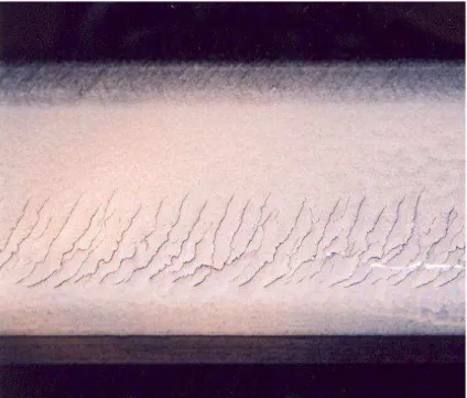
the rail web) at Distances Ranging from 4 to 28 mm from the Gauge Side of the Rail; The Steel Is a 1984 CC CFI Rail Steel ... 13 Figure 6. Progression of Wheel-Tread Surface Fatigue from Microcracks to Fully
Shelled [171] ... 14 Figure 7. Gauge Corner Collapse Can Lead to Deep-Seated Shells with Very Large Chunks of
Metal Spalling from the Rail... 15 Figure 8. Examples of Gauge Corner Collapse ... 16 Figure 9. Gauge Corner Fatigue on a Light Rail System Because of Flattening of Rail (with a
reciprocating stone grinder) and Overloading of the Rail Gauge Corner ... 16 Figure 10. Transverse Defects Initiated by Deep-Seated Shells, Probably from Gauge Corner
Collapse... 17 Figure 11. Vertical Split Head Defect ... 18 Figure 12. A) The Squat Appears as a Dark Spot on the Top of the Rail, B) In Cross Section,
One Can See Two Primary Cracks—a Short Leading One and a Longer Trailing Crack; Photographs Are Courtesy of Makoto Ishida, RTRI, Japan ... 18 Figure 13. The Crushed Head Defect Is Associated with Collapse and Deformation of the
Underside of the Rail Head as a Result of Cracks That Initiate at the Mid-Gauge and
Propagate to the Center of the Rail ... 20 Figure 14. Examples of Wheel Surface Martensite ... 21 Figure 15. A) Thin Streaks of Martensite on the Rail Surface Because of High Creep Rates from
Wheels under High Traction; B) a Spinning Wheel Can Burn a Deep Patch of Martensite into the Rail ... 21 Figure 16. A Shattered Rim Failure [262] ... 22 Figure 17. A Typical Vertical Split Rim [260] ... 23 Figure 18. Hydraulic Mechanism Is No Doubt Contributing to Shelling on This High Rail;
Cracking Is Enhanced by Dye Penetrant ... 26 Figure 19. Ratcheting in Rail Steels Associated with Contact Fatigue ... 27 Figure 20. Cyclic Stresses Associated with a Rolling Contact, Nondimensionalized with Respect
to the Width of the Line Contact (2a) and the Peak Normal Stress (Po) ... 28 Figure 21. Plot of the Stress Trajectory ( zz- xx )/2Po versus xy/Po for One Complete Rolling
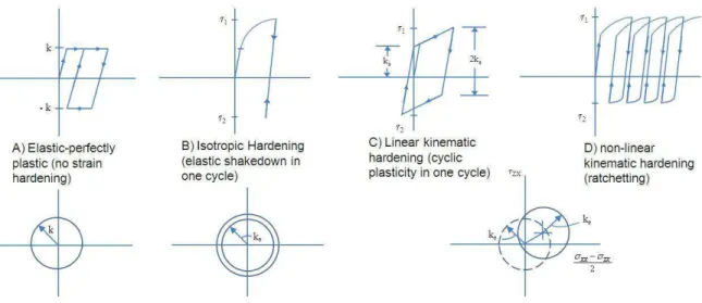
Cycle at Different Depths z/a below the Surface ... 28 Figure 22. Different Models for Yielding of Materials Include Elastic Plastic, Linear Hardening, and Kinematic Hardening ... 29
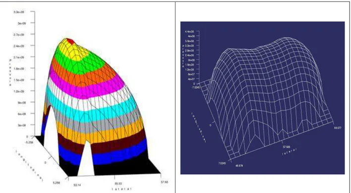
Figure 23. Shakedown Diagrams for A) Line and B) Spherical Contacts [109] ... 29 Figure 24. Harness Distribution on the ―Conformal‖ Ground Profile That Exhibited
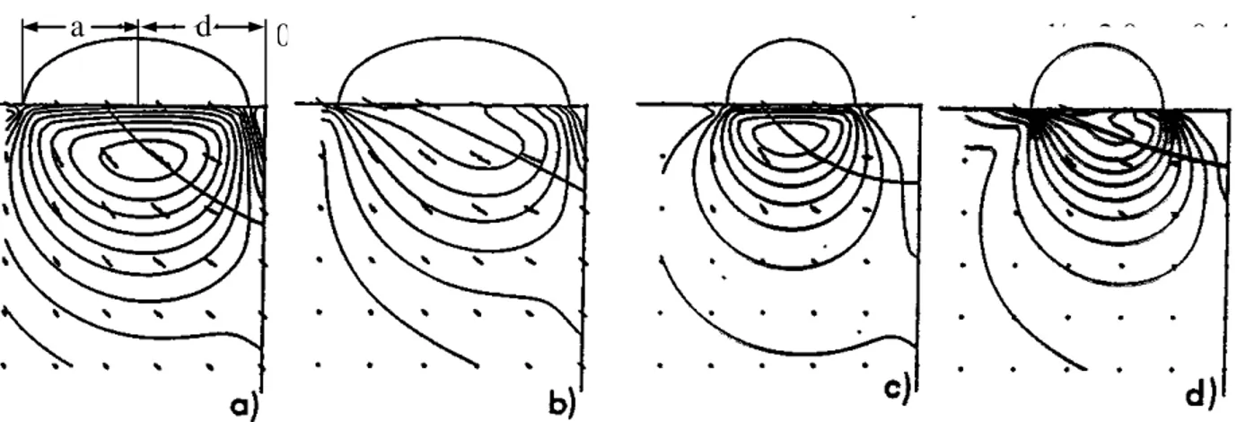
―Unexpected Shelling‖ [255] ... 30 Figure 25. Gauge Corner Collapse Is Associated with Excessive Loading at the Gauge Corner of
the Rail; Modeling the Rail as an Infinite Quarter Space Allows the Arcs of Collapse to Be Predicted for Different Ratios d/a and Traction Coefficient [132] ... 31 Figure 26. With the Dang Van Criterion, Plastic Strain Will Occur in That Portion of the Stress
Cycle a<t<b ... 32 Figure 27. Examples of Nonelliptical Contacts Stress Distributions Calculated Using
Non-Hertzian Models ... 33 Figure 28. The Rate at Which Residual Stress Is Relieved Is a Function of Temperature and
Time [198] ... 36 Figure 29. Crack Propagation Is by One or a Combination of Mode I, Mode II, and Mode III
Stresses ... 38 Figure 30. Effect of Stress on Material Performance [18] ... 43 Figure 31. Effect of Contact Pressure on Nine Different Rail Steels [33] for a Creep Ratio of 10
Percent... 43 Figure 32. Effect of Slip Ratio on Number of Cycles to Failure Based on Laboratory Testing
[33]; the Longest Life Is Achieved with Zero Slip with another Maximum Seen at Roughly 1-Percent Creep ... 44 Figure 33. Lubrication of the Crack Faces Promotes Mode II Propagation, whereas Water in
Properly Oriented Cracks Can Pressurize the Crack Tip and Cause Cracks to Propagate Rapidly in Mode I ... 45 Figure 34. Predicted Crack Growth Rates for Three Different Values of Crack Face Friction
(0.1, 0.18, and 0.6); The Friction at the Wheel-Rail Contact Is in All Cases 0.18 (from Reference 66) ... 46 Figure 35. Eddy Current Systems Can Detect Lipping at the Gauge Corner of Rails [200] ... 52 Figure 36. Three Different Commercially Available Walking Stick Crack Measuring Systems 53 Figure 37. The Prüftechnik Linke & Rühe Inspection System Combines Both Ultrasonic and
Eddy Current Inspection on One Train ... 55 Figure 38. Example Plot of Processed Data from the Speno Rail HC Grinding Scanner System56 Figure 39. Example of the Rail Surface Fatigue Data Collected by MerMec‘s THIS ... 58 Figure 40. The Key Factors Controlling RCF; The Section Numbers Point to Relevant Portions
of the Report ... 61 Figure 41. The Effect of Increasing Inclusion Size/Diameter (d/do) Is to Dramatically Reduce
the Relative Fatigue Limit (Q/Qo) [61] ... 65 Figure 42. The Pearlitic Rail Microstructure Has Layers of iron (black) and Iron
Carbide (white); The Carbide Spacing in the as Manufactured Sample Is Approximately 0.3 Microns ... 66 Figure 43. A) Schematic of Full Traction Curve for Free Rolling, Rolling-Sliding, and Sliding
Freight Wheel Profile against the RE136, 141AB, and NRC-H2 Rail Grinding Template (top of rail friction is 0.45, and the gauge face value is 0.3) ... 70 Figure 44. Traction Forces Measured with Instrumented Wheelsets Running on the Amtrak
Northeast Corridor ... 71 Figure 45. Surface Traction and Subsurface Plastic Flow – Longitudinal and Lateral Traction
Directions for RCF Crack Initiation at Different Locations on the Wheel Tread; One or Several Distinct Bands of Cracks May Appear as a Result of Contact with Tangent Track (TT) or the High Rail (HR) or Low Rail (LR) of Sharp Curves (SC) and Mild
Curves (MC) ... 72 Figure 46. Track Geometry Errors Contribute Directly to Many Instances of RCF: A) Gauge
Tightening over a 6-Foot Length of Track Otherwise at Standard Gauge Lead to a Localized Band of Gauge Corner RCF; B) A Poor Ballast Shoulder Led to a Crosslevel Error and the Formation of a Deep-Seated Shell on Tangent Rail ... 75 Figure 47. Controlling Wear at ―The Magic Wear Rate‖ Maximizes Rail Life ... 76 Figure 48. The RCF Damage Function (1/Nf the number of cycles to failure) as a Function of the
Wear Number T [15]. ... 78 Figure 49. A Dynamic Shakedown Plot Summarizes Contact Conditions for Three Different
Wheel Profiles against the Same Rail Shape As-Is Negotiates a 1,500-Meter, High Cant Deficiency Curve ... 79 Figure 50. The Typical Rail Profile Changes that Arise because of Common Wheel and Rail
Contact Conditions... 80 Figure 51. NRC‘s Complete Set of Eight 200-Millimeter (8 inches) Profiles: TT Is the Tangent
Rail Template, whereas a) H1 to H4 Are High Rail Templates with Progressively More Gauge-Corner Relief and b) L1-L3 Are Low Rail Templates with Progressively More Field Side Relief ... 82 Figure 52. The Worn Rail Profile Is an Envelope of the Worn Wheels that Run over It ... 84 Figure 53. The Improved CP-TF2 Rail Profile Spreads Wear across the Rail Head, Minimizing
Contact at the Gauge Side where cracks Initiate, Placing Most of the Load through the Center of the Rail, but also Allowing the Field Side Metal to Bear a Portion of Stress; This Contact Distribution Is Believed to Be the Best Compromise between Controlling Initiation while Managing Propagation on Existing Defects ... 85 Figure 54. The Coefficient of Friction at the Unmanaged Wheel-Rail Interface Can Vary
Widely, from 0.05 to 0.7 ... 89 Figure 55. Friction Management Involves Two Different Interfaces (top-of-rail/tread-of-wheel
and gage face/wheel flange) with Different Requirements for Each ... 89 Figure 56. The Effect of Friction Management of Wear and RCF – Full-Scale Rig Test Results;
Left to Right: New 60E1 Profile, ―Dry‖ after 100k Wheel Passes, FM 100k Wheel Passes, and FM 400k Wheel Passes (from Reference 257) ... 91 Figure 57. Solid Stick and Fluid Friction Modifier Products Developed by Kelsan Technologies
for Control of Wheel-Rail Friction ... 92 Figure 58. A Spray Nozzle Used to Dispense Thin Films of the Kelsan Friction Modifiers to the Top of Rail, Usually from a Locomotive; A Same Approach Is Taken by Timken to Apply
Figure 59. Crack Initiation and Fatigue Model Presented by Kapoor [139] ... 96 Figure 60. The Friction Transformation Process ―Heals‖ Cracks in a Laboratory Test ... 98
Tables
Table 1. Listing of Those Organizations Publishing Papers Related to Studies of RCF ... 7
Table 2. Rail Defect Classifications... 17
Table 3. Demands on Rail (from Reference 124) ... 34
Table 4. Mechanical Properties of High-Strength Rails (Reference 108, Table 3.3) ... 35
Table 5. Comparing High Cycle Fatigue and Low Cycle Fatigue Approaches to Modeling of Crack Growth ... 39
Table 6. Increasing Hardness Corresponds to Increasing Resistance to the Initiation of RCF; Standard North American Classifications; Typical Values of Shear Strength (k) Calculated at One-Sixth of the Vicker‘s Hardness [170] ... 41
Table 7. Impact Resistance of Rail Steels [Reference 108, Table 3-3] ... 47
Table 8. Example of a Defect Classification and Required Action ... 48
Table 9. Technologies Applied to Rail Testing [Table 1 of Reference 200] ... 50
Table 10. Comparison of the Three Common Detection Technologies Applied to Rail Inspection [extension of Reference 200, Table 1] ... 51
Table 11. General Properties of Wheel and Rail Steels ... 62
Table 12. Prescribed Properties of Rail Steels According to UIC 860V 8 [291] ... 63
L
IST OFS
YMBOLSa,b The half length of the wheel/rail elliptical contact patch in the longitudinal (in direction of travel) and lateral (across the rail) directions, respectively (in metres or inches)
z/a Distance beneath surface – nondimensionalized
x/a Distance in front of the center of the contact patch, nondimensionalized K Shear strength (Pa, psi)
Hv Vickers Hardness uses a pyramid shaped indenter (kg/mm2) HB Brinnell Hardness uses a spherical indenter (kg/mm2)
N, V Normal (or vertical) force loading two bodies together (N, lbf) Po Maximum contact stress (Pa, psi)
T Total traction or shear force (lbf, Newtons) (gamma) The nondimensionalized slip (slip rate/velocity)
Friction coefficient
zx xy
Shear stress (Pa, psi)
Shear stress in the zx and xy planes, respectively
zx xy
Normal stress (Pa, psi)
Executive Summary
Rolling contact fatigue (RCF) is a pervasive and insidious problem on all types of railway systems. Although it is a dominant cause of maintenance and replacements on heavy-haul rail lines, it is also a significant economic and safety challenge for commuter and metro lines. It is a subject of intense research around the globe, with strong academic research being undertaken in Europe particularly, with more practical work being performed in Australia, South Africa, and North America.
The safety implications of RCF include being responsible for approximately 100 Federal Railroad Administration (FRA) derailments annually in North America. The poster child for hazardous RCF is the Hatfield derailment in the United Kingdom, which resulted in 4 deaths and 39 injuries, economic fallout easily exceeding £1 billion, dismemberment of the railway
authority, and manslaughter charges against several railway officials. The economic
implications of RCF to the North American railway industry for rail replacement alone amounts to over USD300 million annually, with costs of inspection and derailments, as well as damage to track and rolling stock further increasing that number. Of the more than USD100 million spent annually on rail grinding in North America, at least 30 percent or more can be attributed to RCF. A review of the types or RCF defects on wheels and rails, causal mechanisms, and monitoring and maintenance practices has been undertaken for the purpose of identifying gaps and the most pressing areas for research and development.
The extensive cross-referencing, combined with a specific listing of leading organizations currently involved in research and development that are included in this report should prove valuable in developing possible future collaborative projects aimed at eliminating gaps in knowledge or practices.
Causal Mechanisms Crack initiation
Two prominent models used in rolling contacts for understanding crack initiation are the Shakedown Limit and the Dang Van Criterion. Their implementation is relatively straightforward, but opportunities exist for better characterizing the material properties upon which they depend. This includes the development of repeatable testing
methodologies that mimic the true state of stress and the short loading duration of the wheel-rail system. The latter is relevant in that the wheel-rail contact loading is typically completed in a very short time (e.g., 0.5 milliseconds (ms)) and high strain rates occur (e.g., 1.0 s-1). Currently, materials characterization tests are typically performed under nearly static conditions.
Although detailed models of the wheel-rail contact and vehicle-track interaction are being developed, the input of realistic operating conditions is sometimes overlooked. As an example, the effect of friction and traction coefficient is well appreciated, but to date, nearly all work assumes a simplified traction-creepage relationship. Laboratory and field evidence suggests that the relationship differs from that of Kalker. Further field
characterization of friction characteristics and implementation in vehicle track interaction (VTI) models is required. Similarly, the distribution of vehicle characteristics, wheel-rail profiles, and material properties is needed.
Crack propagation
The rolling contact involves a complex multiaxial state of stress dominated by a combination of Mode II shear and compressive Mode I stress. Grease and water in the interface dramatically affect the stress state. Reduced friction at the crack face
considerably increases the impact of shear stresses on crack propagation. Water that is drawn into the crack by surface tension can be pressurized toward the crack tip and generate large tensile stresses that drastically accelerate crack growth.
At high contact stress values, RCF life decreases with increasing stress, but below a threshold value, RCF life approaches infinity. A much stronger relationship is seen with the creep ratio in which minimum life occurs at approximately 0.3 percent creep.
High-strength materials better resist crack propagation. Technologies for improving shear strength (hardness) and fracture toughness include minimizing inclusions, ensuring favourable residual stresses, and alloying (most notably with molybdenum).
Monitoring Technologies
It is understood that current ultrasonic measurement systems are able to collect a signature from the rail surface with information relevant to the severity of RCF. No literature was found to suggest that this has been investigated seriously as a technique for assessing surface damage.
Vision systems offer the potential to identify surface cracks and support a fatigue management system, but the capabilities of current instruments is limited. Improved hardware, combined with appropriate interpretive algorithms, could make this approach a reality.
Eddy current systems provide a return signal that is proportional to the length of the surface breaking crack. Such measurements would be extremely valuable for a field study of the relationship between RCF and operating conditions, for safety monitoring of track, for maintenance planning, and for the practice of rail grinding. Work is needed to a) validate available measurement systems; b) demonstrate the reliability in field conditions; c) study the relationship between crack depth and crack length under several environmental and loading conditions; and d) study how the rate of crack growth varies with a multitude of operational factors.
Acceleration-based systems, including instrumented wheelsets and axle–box-mounted accelerometers, are able to detect cases of deep RCF surface defects but are not yet able to support a preventive maintenance program.
Inspection of wheel steels: small, nonmetallic inclusions are believed to be the cause of some wheel failures such as shattered and broken rims. The current statistical sampling and
analysis approach is inadequate for finding random inclusions, and current inspection
technologies (e.g., ultrasonic) are unable to find a 1-millimeter (mm) defect. Improved tools are required.
Management of RCF
Among the tools available for managing RCF, the most powerful ones continue to be development and adoption of improved rail steels, optimized wheel-rail profiles, friction management, and rail grinding.
Work should continue toward developing rail steels that maximize cleanliness and minimize pro-eutectoid ferrite. Bainitic steels, especially lower bainite, appear to offer improved resistance to RCF. Cleaner and cleaner steels may continue to improve resistance to subsurface failure in both rails and wheels.
Although the significant contribution of wheel-rail profiles to minimizing RCF and
techniques for their design is well understood, practical approaches for managing profiles are not well developed. Management tools exist, but their analytical capabilities remain
simplistic, and their penetration into the rail industry poor. Tolerances on wheel and rail profiles remain to be developed. Although various wheel-rail interaction indices suitable for evaluating risk and maintenance requirements have been developed, more can still be done to develop improved criteria and support their adoption by the industry.
Friction management – the ability of friction management to reduce RCF has been
demonstrated recently and the theory is sound, but the practical applications and economic and safety cases still need to be convincingly demonstrated for a range of systems.
Rail grinding is a well established method of removing surface defects and profiling rail. The optimal rail grinding interval and metal removal as a function of specific operating conditions (e.g., axle loads, metallurgy, track curvature, and rolling stock characteristics) is not known, except by generalized ―best practice‖ principles. The integration of VTI, rail defect, and rail wear data into rail grinding decisions remains an area for development. The mechatronic rail grinder—one that measures profile and cracks at the lead end of the train, computes the required speed and patterns, and measures the results on the tail end—remains a theoretical and practical challenge.
Control of Track Geometry Defects
Track geometry perturbations are often associated with local clusters of RCF. These
perturbations can be identified by train-based acceleration measurements with the probability of clusters arising readily predicted by dynamic models. The severity of RCF depends not only on the characteristics of the track geometry defect but also on the profiles, friction conditions, truck characteristics, track curvature, and train speed. Although operating limits for geometry errors can thus be established to minimize fatigue, it would be difficult to do so in a general sense for the railroad industry because of the system-specific dependencies.
Improved Suspensions
In the United Kingdom, it has been noted that as train speeds increase on the network, the
primary yaw stiffness has also increased to meet the need for improved ride quality. This in turn has generally compromised curving performance and increased the RCF damage severity, especially in shallower, high cant deficiency curves. However, it was further noted that careful suspension geometry design may mitigate the adverse effects of higher primary yaw stiffness. In North America, the contribution of advanced (e.g., M976 compatible) trucks to reduced RCF has not been well quantified, but there is some evidence of improved curving performance resulting in longer wheel life, including with respect to shelling. Because the truck designs are intended and tested to provide reduced curving resistance, and thereby ―lower the stress state,‖ it is reasonable to expect that reduced rail RCF will follow also. Yet outside of computer models, this has been difficult to quantify.
VTI Monitoring Systems
Accelerometers and strain-gauged components (including instrumented wheelsets) onboard rolling stock have proven effective in identifying high dynamic and damaging forces as well as unsafe conditions such as elevated risk of wheel climb. Once regions of high dynamic forces were identified, there is reasonably a correlation with localized incidents of RCF. Under quasi-static curving, high forces can be correlated to increased rates of RCF development. However, a full quantification of high RCF areas would require measurement of not only force but also angle of attack and longitudinal creepage as well as the precise location of the contact patch. This is beyond the capabilities of current onboard or wayside instrumentation and partly explains the widespread use of dynamics models to explain the problem.
1.
RCF of Wheels and Rails
RCF has been a subject of significant scientific scrutiny for several decades, but as tools and practices for controlling corrugation and wear have become increasingly effective, RCF has emerged as a governing reason for rail replacement and maintenance and for rail failure and safety concerns. Since the mid-1990s especially, much research has been undertaken on all continents to understand the fundamental causes of RCF, approaches to modeling, and
development of maintenance approaches. The intent of this review is to identify the areas where improved knowledge and practices need development before a fully effective strategy for
managing RCF can be realized.
1.1 The International Scope
RCF is a problem that knows no borders. It is the subject of research in every railroading country in the world including the following:
United States: Rail grinding practices [228, 254] and steel developments [213, 214, 263] are the primary approaches taken by U.S. railroads to deal with RCF. The rail steels have progressively increased in hardness, with 400 BHN rail now commonly used, especially but not exclusively in curved track.
Canada: RCF is a major initiator of broken rails and is the main reason for rail grinding and loss of rail life. Work in that Nation has focused on optimal rail grinding practices and profile design [47] and proving friction management [52, 218, 250] for controlling RCF.
United Kingdom: As a result of the Hatfield derailment in 2000 because of a broken rail initiated by surface RCF, there has been intense study into the causes of and remedies for gauge-corner cracking [21, 44, 88]. Strong contributions have been made in the past several years related to the modeling of crack initiation [76], understanding the effect of track curvature and track geometry perturbations [15] and developing systems for managing RCF [272]. In addition, there has been a tremendous effort to develop comprehensive models of the interaction between vehicle and track and the impact on RCF [15, 217].
Sweden: On the electrified heavy iron ore lines, 25-ton axle loads cars run of UIC 60 rail with UIC 1100 and UIC 900 metallurgy. The rail suffers severe head checking and spalling, primarily in switches and the high rail of curves, which contributes to broken rails. Corrugation and gage face wear are significant concerns also [89]. Rail grinding has proven very effective in mitigating the costs of RCF [194]. Sweden has a very active railway research program that includes significant research effort into RCF [e.g., 56, 58, 60, 210, also Table 1].
France: The focus is on RCF appearing on the rails of its high-speed lines, especially gauge corner cracking [43] and squats [40].
Japan: The surface defect of greatest concern is squats [112] with the main treatment being preventive rail grinding [221]. In the mid-1990s, 70 percent of the 220 kilometers (km) of rail replaced annually on the Tokaido Shinkansen was for RCF [148]. Head checking and shelling have also been experienced on the high-speed lines and on lines
China: With the dramatic increase in rail traffic, the tonnage on some Chinese lines has escalated dramatically. RCF is becoming increasingly problematic [27], with shelling of the high rail gauge corner and on the top of low rail being most common. The approach to treatment appears to focus the adoption of improved rail steels [305].
Australia: Leading the world in terms of axle load, this country has been at the forefront of developing rail grinding strategies [153] and advanced rail and wheel steels [178, 280] to deal with problems of wear, fatigue, and plastic flow. A significant finding reported in 1987 is that high strength rails, and in particular the head-hardened varieties, showed a strong improvement in fatigue performance [179].
South Africa: Pioneered steerable bogies [82] for the reduction of shear stress, wear, and fatigue. More recently, the development of integrated systems for managing RCF [80] have been developed. As in other heavy haul countries, improved rail grinding practices [231] continue to form a key part of the RCF management strategy.
Germany: German railways (DB AG) has suffered from various forms of surface fatigue for many years, with head checks developing most rapidly on newly installed high rails in shallow curves [91,193]. Rail grinding and improved rail profiles [91] as well as high-strength rail steels [99] are the current approaches taken to treat the problem.
Russia: RCF defects on rails and wheels continue to be a challenge for the Russian railways [304]. Improved steels [234] and rail/wheel profiles [303] appear to be the prime focus of researchers in Russia.
Brazil: RCF on wheels and rails in Brazil has focused mainly on its iron ore mining railroads [70]. Recent projects to increase axle load and dramatically increase annual tonnage shipped from those same mines have only exacerbated the problem. Improved steering trucks [283] and rail grinding [203, 236] are the primary tools for its treatment, with friction management also gaining consideration [125].
An analysis was conducted of RCF-related publications between 1999 and 2010 as listed in the Scopus database. It should be noted that the Scopus database does not capture the numerous papers that are being presented on the subject in railway-related forums such as the American Railway Engineering and Maintenance-of-Way Association, the International Wheelset Congress, the International Heavy Haul Association, and the World Congress on Railway Research. The numbers of publications counted by Scopus will naturally be skewed toward academic institutions that place a strong emphasis on generating peer-reviewed publications. Also, in Scopus, where there were multiple participants in a publication, each one is given credit for the publication, which helps to explain why some commercial companies, which sponsor research at universities, show relatively high number counts. Despite these limitations, the summary in Table 1 is believed to a fair list of the major organizations conducting research into RCF.
Table 1. Listing of Those Organizations Publishing Papers Related to Studies of RCF
Organization No. of
pubs.
Country/ Headquarters
Chalmers Tekniska Högskola (27) 27 Sweden
University of Sheffield (16) 16 U.K.
RTRI, Railway Technical Research Institute (7) + Vehicle Strength (1) + Track Dynamics Laboratory (1) + Frictional Materials Laboratory (1) + Vehicle and Bogie Parts Strength (1)
11 Japan
Transportation Technology Center, Inc. (9) + TTCI U.K. Ltd. (1) 10 U.S./U.K.
University of Birmingham (9) 9 U.K.
Voest-Alpine AG (7) + Voest-Alpine Schienen GmbH (2) 9 International
AEA Technology Rail bv (4) + AEA Technology (4) 8 Netherlands/U.K.
Newcastle University United Kingdom (7) + Newcastle University (1) 8 U.K.
Semcon AB (6) (CARAN) 6 Sweden
Southwest Jiaotong University (6) 6 China
Imperial College London (5) 5 U.K.
Politecnico di Milano (5) 5 Italy
Kanazawa University (4) 4 Japan
Politechnika Warszawska (4) 4 Poland
Sumitomo Kinzoku Kogyo Kabushiki-gaisha (3) (Sumitomo Metal Industries Ltd.) + Amagasaki (1)
4 Japan
Centre for Surface Transportation Technology NRCC (3) 3 Canada
Corus Rail Technologies (3) 3 U.K.
Deutsche Bahn (3) 3 Germany
KRRI (2) + Korea Railroad Research Institute (1) 3 South Korea
RVD Consulting, Inc. (2) + RVD Consulting (1) 3 U.S.
Spoornet (2) + Spoornet, Materials Engineering (Rollstock) (1) 3 South Africa
Swinburne University of Technology (3) 3 Australia
TSC Inspection Systems (3) 3 U.K.
Università degli Studi di Brescia (3) 3 Italy
Vanderbilt University (3) 3 U.S.
Manchester Metropolitan University (3) 3 U.K.
All-Russ. Railway Research Institute (2) 2 Russia
Banverket (1) + Banverket (1) 2 Sweden
Booz Allen Hamilton, Inc. (2) 2 U.S.
Daneshgahe Elm va Sanat e Iran (2) (School of Mechanical Engineering, Iran University of Science and Technology, Narmak, Tehran 16884, Iran)
2 Iran
Delft University of Technology (2) 2 Netherlands
Hiroshima University (2) 2 Japan
Hunter Holiday Consulting (1) + Hunter Holiday Consulting (1) 2 U.S. Interfleet Technology Ltd. (1) + Interfleet Technology AB (1) 2 Sweden/U.K.
Luleå tekniska Universitet (2) 2 Sweden
SP Technical Research Institute of Sweden (2) 2 Sweden
The Royal Institute of Technology KTH (2) 2 Sweden
The University of Warwick (2) 2 U.K.
1.2 Safety Implications of RCF
In some operations RCF is the main contributor to broken rails and derailment. Examples include
the previously mentioned Hatfield derailment in the United Kingdom in which 4 lives were lost and 107 people injured,
a 2006 derailment in New Brighton, PA, where 23 tank cars derailed with several falling into a river and 20 of the cars releasing ethanol that burned for 48 hours (h) [190], and
two RCF-caused broken rail derailments on South Africa‘s Spoornet railroad in April 2004. The catastrophic rail failure was the result of gauge corner cracking initiating large (e.g., 80 percent of the head area) transverse defects.
Reference 20 notes that the loss of a length of the rail head, from a few millimeters to a couple of meters, is sufficient for precipitating a derailment and that defects that either run the length of the rail or appear in clusters are the most dangerous. The former category includes vertical split head and head-web separation, whereas RCF defects such as gauge corner cracking, transverse defects, and squats are examples for the latter. Isolated defects such as a clean rail break do not frequently lead to derailments because the gap that arises is normally bridged by the passing trains.
FRA maintains a database of accident statistics, and the frequency of rail failure related to rail defects can be extracted. For 3 years, 2006–2008, there were a total of 246 derailments as a result of cause ―T220 Transverse compound fissure‖ and 145 derailments for cause ―T207 detail fracture – shelling head check‖ with 40–50 percent as mainline derailments. These are the fourth and ninth primary causes of train accidents listed in the database [287]. Although the T207 incidents are clearly a consequence of RCF, only about half of the first category is due to RCF, the remainder occurring in older rail with internal defects.1 Taken together, the total of 268 RCF-caused derailments represents approximately 10 percent of all derailments over that period. In 2005 specifically, FRA reported track-caused derailments numbered 1,024 with 57 nonfatal casualties—RCF accounted for roughly 105 (10 percent) of those, with 7 (13 percent) nonfatal casualties.
The necessary joining of rails through welding is an ongoing location of rail failure, with 42 percent of total rail defects (1995) being from bolt holes and defective welds.
Analysis of FRA data from the 1980s [300] showed that one broken rail derailment occurs for every 770 defects. For contact stress-related defects (such as transverse defects and vertical split heads), the rate rises to 1 in 526. In a separate analysis [209], data for an unnamed class 1
railroad in the United States yielded that the number of rail breaks per derailment was approximately 300 in 1989.
Statistics summarizing the number of rails found damaged or broken are given in Reference 64 for several countries including France, Germany, India, Japan, the Netherlands, South Africa, and the United Kingdom.
1.2.1 (Rail) Ultrasonic No-Tests
Surface fatigue is a serious hazard because it prevents the successful transmission of ultrasonic waves to the base of the rail and back. Failure to detect the return signal results in a ―no-test‖
1
and the inspector is then usually required to stop and perform a hand test of the rail using a more sensitive manually operated system. This stopping and starting severely curtails the productivity of the inspection and reduces track availability for revenue traffic. Because of the risk of a rail break and derailment occurring from undetected subsurface defects, failure to achieve a test on many railroads requires removal of the affected length of rail.
1.3 Types of RCF Defects
The different types of RCF defects have been aptly reviewed by several authors over several years including References 2, 20, 57, 83, 90, 88, 174, and 175. They are summarized briefly in the following sections.
1.3.1 Rail Gauge Corner Cracking
These are thin cracks appearing at the gauge corner of the rail (Figure 1), appearing most often on the outer rails of curves and sometimes on tangent rails but infrequently on low rails. They develop as a result of high wheel-rail contact stresses coupled with sufficiently large shear stresses because of slip between the wheel and rail. Gauge corner cracking (GCC) is often regularly spaced and may occur for long lengths of track (e.g., the entire curve) or may be found in clusters. In the latter case, it is usually associated with track geometry perturbations.
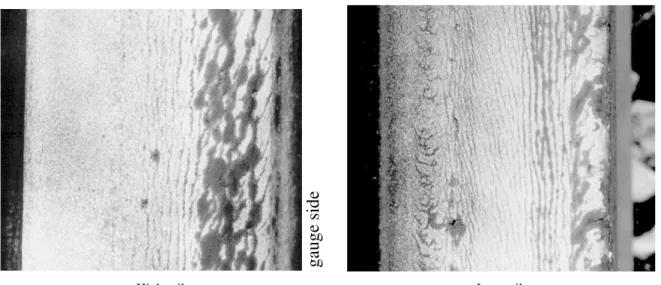
Figure 1. Well-Defined Gauge Corner Cracking from High-Speed Passenger Operation On freight railroads, the cracking when left to develop looks typically like the (dye penetrant enhanced) samples shown in Figure 2, with the gauge corner of the high rail and the field side of the low rail most heavily afflicted.
ga
uge
side
High rail Low rail
Figure 2. Cracking of the High and Low Rails, Dye Penetrant Enhanced
As GCC progresses, the cracks grow longer and deeper into the component and may eventually lead to pits and shells on the rail surface. Figure 3 shows examples of the different stages of crack growth on rails.
11
A) Moderate checking at the gauge corner of the rail.
E) Moderate checking across the low rail surface.
B) Crack orientation changes due to different creep directions of leading and trailing axles.
F) Field side cracking eventually deteriorates into plastic flow and shelling.
C) High rail shelling.
G) Moderate spalling at crown of rail is difficult to remove through grinding. D) Alternating wet/dry
conditions shallow shelling.
H) Heavy, but shallow RCF on flattened low rail.
Hig h Ra il L o w R ail F ig ure 3 . E x a m ples o f T y pic a l H ig h a nd L o w Ra il Chec kin g a nd Sh elli ng
1.3.2 Wheel Tread Cracking
Cracking of the wheel surface parallels that of the rail: excessive cyclic shear stresses at the surface cause incremental plastic flow, and when the total strain exceeds the ductility limit, a crack forms. These cracks can initiate below the surface or at the surface, depending on the friction coefficient. The orientation of the cracks is perpendicular to the direction of traction, and because of the typical orientation of creepage, under wet conditions, the cracks at the field side of the wheel tend to propagate quickest [171]. Although extensive crack patterns can occur at the flange root of the wheel, it is unusual for them to propagate into shelling.
A)
B)
Field Flange
Figure 4. A) Cracks at the Field Side of the Wheel Are Typically Most Severe; B) Extensive Cracking at the Flange Root, Like That Seen Here, Is Much Less Common
1.3.3 Rail and Wheel Shelling
Shelling is the loss of large chunks of metal as a result of either:
Surface and/or subsurface cracks linking up with other cracks below the surface such that the material above is no longer connected to the parent rail (Figure 5) or wheel (Figure 6) and drops out; or
Collapse of the rail gauge corner because of excessive loading and shear failure along a ―slip line.‖ Although shelling from gauge corner collapse occurs preferentially at stringers of alumina inclusions [35], even in the cleanest steel, too many high stress loads at the gauge corner will cause it to yield along a slip line [170]. This defect is often referred to as the ―deep seated shell.‖
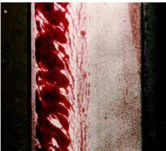
Figure 5. Shelling of a Rail; Shown Are Longitudinal Sections Machined Vertically (parallel to the rail web) at Distances Ranging from 4 to 28 mm from the Gauge Side of the Rail; The Steel Is a 1984 CC CFI Rail Steel
A) Microcracks on the field/rim side of a heavy haul wheel. B) Microcracks on the field/rim side of the high-speed wheel.
C) Well-defined cracks on the field/rim side of the wheel. D) Deeper cracks on the field/rim side of the wheel tread with material starting to shell out.
E) Incipient shells initiating at the field/rim side of the wheel.
F) A fully shelled wheel.
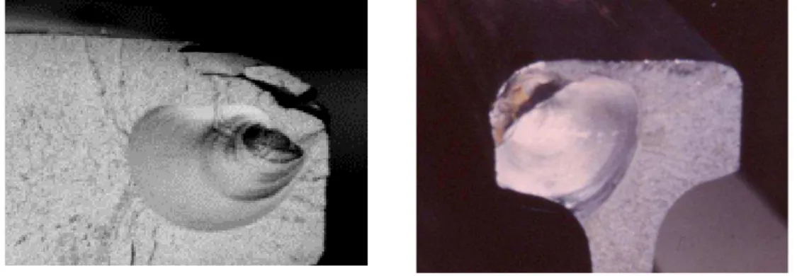
A) Cross section of rail with the microstructure enhanced shows gauge corner collapse.
B) Examples of shelling from gauge corner collapse.
Figure 7. Gauge Corner Collapse Can Lead to Deep-Seated Shells with Very Large Chunks of Metal Spalling from the Rail
Poorly restrained high rails that rotate outwards under load (Figure 8A), well-lubricated rail with a particularly high-stress gauge corner shape (Figure 8B), and even some dry rails (Figure 8C) see large chunks of metal slough from the gauge corner. The most effective treatment for this is ensuring the implementation and maintenance of proper rail shapes that eliminate the
overloading, reducing the stress for each contact and distributing contacts over a wider portion of the railhead. Modeling the system as a quarter space (see Section 2.1.2.1) found that in practice it is necessary to minimize the number of wheels that touch the railhead within three-eighths of 1 inch (9 mm) of the gage face to avoid gauge corner collapse.
A) Loss of rail cant due to rail seat abrasion resulted in overloading of the gauge corner
B) Well-lubricated rail with a sharp gauge corner
C) Gauge corner collapse in a dry environment
Figure 8. Examples of Gauge Corner Collapse
In any case, shells typically develop under the gauge corner of the high rail and most commonly on heavy haul railroads. However, they have also been found on tangent track with local crosslevel errors (see Section 4.5 for examples) and on light axle load transit systems with particularly poor wheel-rail profile matching (Figure 9).
Figure 9. Gauge Corner Fatigue on a Light Rail System Because of Flattening of Rail (with a reciprocating stone grinder) and Overloading of the Rail Gauge Corner
1.3.4 Rail Transverse Defects
Transverse defects such as those shown in Figure 10 are the cause of many broken rails and subsequent derailments. These defects are initiated by shells in the presence of metallurgical inclusions, most commonly oxide stringers. Although the defect may be initiated by RCF, the development of the defect itself is not a rolling contact phenomenon. The transverse crack propagates as a result of the combination of bending stress from wheel loads, residual stress from manufacture, and thermal stress from rail contraction in winter. This process has been examined in detail by several authors [e.g., 29, 118].
Standard railroad classifications consider the rail defects listed in Table 2. Of the 22 listed, only 3 defects are directly the result of RCF.
Table 2. Rail Defect Classifications
DTYPE Definition DTYPE Definition
BBJ Broken Base – Joint TDC Compound Fissure BBO Broken Base – Outside TDD Detail Fracture BHJ Bolt Hole Crack – Joint TDT Transverse Fissure BHO Bolt Hole Crack – Outside TDW Welded Engine Burn BRJ Broken Rail – Joint HWJ Head & Web - Joint
BRO Broken Rail - Outside Joint HWO Head & Web - Outside Joint DWF Defective Field Weld PRJ Piped Rail - Joint
DWP Defective Plant Weld PRO Piped Rail - Outside Joint EBF Engine Burn Fracture SWJ Split Web - Joint
HSH Horizontal Split Head SWO Split Web - Outside Joint HSJ Horizontal Split Head - Joint VSH Vertical Split Head
Figure 11. Vertical Split Head Defect
1.3.5 (Rail) Squats
The squat is a surface defect most commonly associated with high-speed rail and areas of high tractive effort. It is characterized as a shallow depression more or less in the center of the rail head on tangent and mildly curved track. This depression is the result of subsurface cracking, reduced strength of the material, and deposits of debris in that depression, giving it the
appearance of a dark spot.
A) Rail squat B) Cross section showing the shorter leading crack and the longer trailing crack
Figure 12. A) The Squat Appears as a Dark Spot on the Top of the Rail, B) In Cross Section, One Can See Two Primary Cracks—a Short Leading One and a Longer Trailing Crack; Photographs Are Courtesy of
Makoto Ishida, RTRI, Japan
A cross section of the squat shows two cracks; a short leading crack (in the direction of travel) and a much longer trailing crack each propagating at approximately 30° from horizontal (Figure 12B). Because the stress intensity at the tip of the trailing crack is higher than on the leading crack for driving wheels [95, 143], the trailing crack grows longer and more rapidly in areas of high tractive effort. From the trailing crack, many small branch cracks tend to initiate, one of which may turn downward into the head of the rail and initiate a transverse fracture. These cracks are especially problematic because, shielded by the long trailing crack, they are often not detected by conventional ultrasonic measurement systems (see Section 1.2.1). The causes of squats continue to be a subject of some debate, with two different mechanisms currently proposed:
1. On the Japanese railways, a thin martensitic layer exists along extensive stretches of the rail. This is postulated to be associated with the high levels of tractive effort used on those
systems and microslip at the wheel-rail contact. The brittle martensite readily cracks and initiates a surface crack that then propagates, in response to the rolling contact forces, leading to trailing cracks typical of squats [112].
2. As a general principle, high tractive effort is a leading cause of excessive surface shear that initiates classical RCF cracks [43]. These too may initiate surface cracks that then develop into the leading and trailing cracks seen in Figure 12B.
The treatment in all cases has been the frequent grinding of a thin layer of metal from the rail surface to remove the most damaged surface layer where the squats are initiated. Frequent preventive grinding has proven to be an effective treatment on the Shinkansen system [148]. From a detection and maintenance perspective, Li et al. [156] have found that the dimensions and location of squats could be correlated with certain wheel-rail dynamic interactions (force and wavelength), leading the way perhaps eventually to potential early detection and preventive maintenance.
1.3.6 (Rail) Crushed Heads
Sometimes RCF cracks progress toward the center of the rail head, and with subsequent fretting at the crack faces and shearing of material, this area of lower structural integrity ―crushes‖ under the heavy loading. The local vertical perturbation that results is then subjected to further
deformation and plastic flow from increasingly heavy impact loads from passing wheels (Figure 13).
Crushed heads are typically about one-quarter to one-half meter in length. They are characterized by increased frequency and growth of large surface cracks and plastic flow to one or both sides of the running surface. The concentration of cracks is usually caused by a local stress raiser associated with improper rail grinding, lack of rail grinding, track irregularities, dirty steel, or some combination of all of these factors. Grinding can prolong the life of crushed-head–affected rail by either removing damaged material or moving the contact band away from the stress raiser [172]. Crushing is especially problematic on older rail, often having significant vertical wear, where the head may collapse entirely. The crushed head defect and its treatment are discussed in Reference 47.
Figure 13. The Crushed Head Defect Is Associated with Collapse and Deformation of the Underside of the Rail Head as a Result of Cracks That Initiate at the Mid-Gauge and Propagate to the Center of the Rail
1.3.7 (Wheel) Spalling
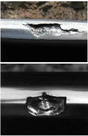
Sliding of the wheel leads to severe temperature increases at the wheel-rail contact patch, and damage to the wheel is especially acute as the thermal energy generated at the slide is distributed over a relatively long length of rail but only over a very short portion of the wheel (the opposite case occurs for the spinning wheel). The temperature on the slower moving contact (the wheel in this case) often rises beyond the transition temperature of pearlitic steel (723°C). When the wheel turns further, the contact patch cools very rapidly, and a white-phase martensite forms. This martensite is very brittle and cracks when the wheel rolls over it. These surface cracks then propagate into the wheel surface. In addition, the spall has changed the geometry of the running surface and is associated with impact. So at the wheel slide location on the wheel tread, there is a combination of brittle martensite and impact. The martensite ―spalls‖ out, and with heavy impacting there is often little evidence of it still in the contact region. Although the mature defect might look like a regular wheel shell, its initiation mechanism, and hence the methods for its prevention, is very different. Reference 174 discusses the considerable differences between shells and spalls and how they can be distinguished.
A light martensitic contact patch at a wheel slide location with cracking starting.
Chain flats (etched in this figure) due probably to a dragging brake on a lightly loaded car, can initiate spalling around the circumference of the wheel.
Figure 14. Examples of Wheel Surface Martensite
On the rail, a completely analogous effect arises because of the spinning of the wheel on the rail. High tractive effort can leave a more or less continuous thin layer of martensite on the surface of the rail, which has been postulated as the causal mechanism of rail squats (see Section 1.3.5). On a macroscopic scale, a wheel burn is a deep layer of martensite that, upon subsequent wheel passes, develops a whole network of surface cracks, anyone of which might be the cause of a broken rail.
A) With a perchlorate etchant B)
Figure 15. A) Thin Streaks of Martensite on the Rail Surface Because of High Creep Rates from Wheels under High Traction; B) a Spinning Wheel Can Burn a Deep Patch of Martensite into the Rail
1.3.8 (Wheel) Shattered Rim
The shattered rim is associated with a subsurface defect and adverse internal stresses. It is not a common defect—in 1999, approximately 300 were reported [262] in the North American interchange service, accounting for approximately 0.06 percent of wheel removals. However, because of the catastrophic potential of a failure, they are considered to be a problem. The
Union Pacific Railroad reported that 65 percent of its railroad wheel failures were due to shattered rims [159].
The shattered rim crack usually initiates approximately 12–20 mm below the running surface and then propagates roughly parallel with the wheel tread, eventually exiting out the rim side of the wheel. If a rim crack is discovered, then the wheel can be removed proactively; otherwise, a section of the wheel rim can separate from the wheel [262]. Many shattered rim failures develop early in wheel life—more than half fail within the first 10 percent of available rim thickness and more than 90 percent of the failures occur within the first 50 percent of the available wheel thickness.
Figure 16. A Shattered Rim Failure [262]
Metallurgical examination of shattered rim failures from a high-speed train operation reported in Reference 290 found that the bulk are due to clusters of hard (usually aluminosilicate) defects and that the best treatment is ensuring steel microcleanliness and NDT testing. Reference 262 reports that in the freight experience, the key to avoiding shattered rims is to minimize voids and porosity in cast wheels and aluminum oxide inclusions in forged wheels. A combination of ensuring internal defects smaller than 1 mm, coupled with more rigorous ultrasonic inspection, has eliminated the problem of shattered rims in South Africa [177]. The same is true in North America, and the improved casting process has considerably reduced the number of shattered rims [259], but research is ongoing to optimize the inspection and maintenance plan for the hundreds of thousands of legacy wheels of older metallurgy still running in the system [159].
1.3.9 (Wheel) Vertical Spit Rim
The vertical split rim is a defect that originates from a wheel shell (Section 1.3.3) or spall (Section 1.3.6) with a significant circumferential length of the wheel tread, usually from the rim/field side, separating from the wheel. Inspection of several such failures found that the wheel typically has a hollow tread and false flange, so that rim/field side loading (such as when the wheel contacts the low rail in a curve) could cause sufficiently high tensile bending stress precipitating the failures.
Interestingly, the failures do not seem to relate strongly to the remaining thickness of the rim, nor was the type of metallurgy, wheel diameter or production process (cast versus forged) a common factor.
Less commonly, a length on the flange side can break from the wheel.
Figure 17. A Typical Vertical Split Rim [260]
1.4 Economic Implications of RCF
The replacement of rail represents a large capital expense for any railroad, ranging from about USD375,000 per track-mile on a conventional freight railroad to USD2 million on underground mass-transit lines. Reducing the unnecessary loss of metal for fatigue related reasons can provide benefits exceeding many millions of dollars annually to a railroad. Data from North America suggest that 15–22 percent of all rail replacement is due to surface and subsurface-initiated defects [20]. For the U.S. and Canadian class 1 railroads in 2007, 20 percent of roughly 700,000 tons of rail purchased represents USD110 million,2 whereas 20 percent of the total rail replacement costs (includes installation costs) recorded by those same railroads amounts to at least USD220 million. The cost of RCF defects to the European rail system was estimated in 2000 to be roughly €300 million (USD417 million) annually, but following the Hatfield
derailment and increased recognition of RCF in Europe, that number has certainly risen [88]. In the United Kingdom alone, extra penalty payments to train operators after the Hatfield
derailment and replacement costs of switches or crossings in which gauge corner cracks were found amounted to £561 million (USD917 million) in 2000–2001 [208]. In 2004, the annual cost of RCF to network rail alone was estimated as being at least £200 million (USD327 million) and included RCF cracking of wheels [51].
In 2005, the most recent year for which cost information is available, RCF would account for approximately 105 derailments and USD30 million in FRA reportable costs, along with 7
nonfatal casualties. On the mechanical side, 22 accidents as a result of broken wheel flanges and broken rims amounted to nearly USD11 million in FRA costs in 2005. Since FRA reported costs
that do not include the cost of clearing up the train wreck or the major cost of damage to the rolling stock, the true costs are likely to be considerably higher—roughly twice as much according to Reference 301.
A journal review in Railway Age [161] quotes an FRA source:
―Rail flaws are a top industry liability. Estimated to cost $455 million annually-including $109 million for related derailments; $70 million for train delays; $149 million for repairs and maintenance; and $127 million for inspections.‖
Internationally, RCF in the late 1990s accounted for approximately 60, 25, and 15 percent of all defects found by East Japan railways, French Railways (SNCF), and Railtrack (U.K.),
respectively [20]. Rail grinding internationally is a USD250–3503 million business, and it is one that is growing as knowledge and demand rises in countries such as India, China, and Brazil. In North America, the costs for rail grinding on a large freight railroad are typically on the order of USD800 per mile of track, with the North American market for rail grinding being roughly USD100–1203 million per year. Although grinding was in the 1970s initially tasked with treating corrugation, modern steels and regular rail grinding have caused RCF to supersede corrugation as the main cause for rail grinding. If RCF could be eliminated by other means, such as improved steels, profiles, or friction management, then the amount of rail grinding required annually could easily be reduced by 30 percent or more.3
The annual cost of rail inspections for defects is not known, but although not all defects are due to RCF (other causes include broken welds, base plate cracks, etc.), there is no doubt that a considerable fraction of the cost can be attributed to the problem. In the European Union, the cost of rail defects, a large percentage of which are initiated by RCF, has been estimated at €2 billion (USD2.8 billion) per year and, on this basis, became the UIC‘s first World Joint Research Project [20]. The cost of research into RCF is significant in itself—for example, the European ICON project was a roughly €1.5 million (USD2.1 million) effort to address RCF [19]. Next, add to this the value of lost revenue because of track outages for inspection and
maintenance, along with the safety impacts already discussed in Section 1.2, and clearly, there are opportunities for improved understanding, inspection, and treatments to significantly reduce the economic costs of RCF.
3
Numbers provided by Alan Zarembski, author of The Art and Science of Rail Grinding (Simmons Boardman Press, 2005).