Publisher’s version / Version de l'éditeur:
Vous avez des questions? Nous pouvons vous aider. Pour communiquer directement avec un auteur, consultez la première page de la revue dans laquelle son article a été publié afin de trouver ses coordonnées. Si vous n’arrivez pas à les repérer, communiquez avec nous à PublicationsArchive-ArchivesPublications@nrc-cnrc.gc.ca.
Questions? Contact the NRC Publications Archive team at
PublicationsArchive-ArchivesPublications@nrc-cnrc.gc.ca. If you wish to email the authors directly, please see the first page of the publication for their contact information.
https://publications-cnrc.canada.ca/fra/droits
L’accès à ce site Web et l’utilisation de son contenu sont assujettis aux conditions présentées dans le site LISEZ CES CONDITIONS ATTENTIVEMENT AVANT D’UTILISER CE SITE WEB.
27th International Conference on Offshore Mechanics and Arctic Engineering
[Proceedings], 2008
READ THESE TERMS AND CONDITIONS CAREFULLY BEFORE USING THIS WEBSITE.
https://nrc-publications.canada.ca/eng/copyright
NRC Publications Archive Record / Notice des Archives des publications du CNRC :
https://nrc-publications.canada.ca/eng/view/object/?id=5323169b-64c9-472f-9ef7-6efe3ddb3757
https://publications-cnrc.canada.ca/fra/voir/objet/?id=5323169b-64c9-472f-9ef7-6efe3ddb3757
NRC Publications Archive
Archives des publications du CNRC
This publication could be one of several versions: author’s original, accepted manuscript or the publisher’s version. / La version de cette publication peut être l’une des suivantes : la version prépublication de l’auteur, la version acceptée du manuscrit ou la version de l’éditeur.
Access and use of this website and the material on it are subject to the Terms and Conditions set forth at
Assessment of thermal protection in life rafts in passenger vessel
abandonment situations
Copyright 2008 by ASME 1
Assessment of Thermal Protection of Life rafts in
Passenger Vessel Abandonment Situations
Lawrence Mak, Andrew Kuczora National Research Council Canada
Institute for Ocean Technology Arctic Avenue, Box 12093, Station A
St. John's, NL Canada A1B 3T5 E-mail: Lawrence.Mak@nrc-cnrc.gc.ca E-mail: Andrew.Kuczora@nrc-cnrc.gc.ca Michel B. DuCharme System of Systems (SoS) Defence R&D Canada - Valcartier
2459 Pie-XI Blvd North Quebec, QC
G3J 1X5
E-mail: Michel.Ducharme@drdc-rddc.gc.ca
James Boone, Rob Brown Marine Institute,
Offshore Safety and Survival Center, Box 4920 St. John’s, NL Canada A1C 5R3 E-mail: james.boone@mi.mun.ca E-mail: Robert.Brown@mi.mun.ca Brian Farnworth Helly-Hansen Canada Limited
Home office: 2020 Bennett Rd
Kelowna, BC Canada, V1V 2C1 E-mail: BFarnworth@helly.ca
Kerri-Ann Evely, Fabien A. Basset, Scott MacKinnon
Memorial University of Newfoundland St. John's, NL Canada A1C 5S7 E-mail: Kerri-Ann.Evely@nrc-cnrc.gc.ca E-mail: Fbasset@mun.ca E-mail: smackinn@mun.ca ABSTRACT
Inflatable life rafts are currently used on almost all passenger, fishing and commercial vessels, and offshore oil installations. Worldwide, life rafts are the primary evacuation system from fishing vessels with relatively small crews to large Roll on/Roll off passenger vessels with over a thousand passengers and crew. While International Maritime Organization (IMO) standards currently require inflatable life raft components to “provide insulation” or “be sufficiently insulated”, there are no performance criteria for these requirements (IMO, 1996). In a passenger ship abandonment situation in cold water, passengers may be wearing very little personal protective clothing. Therefore, life rafts provide the only significant thermal protection against the cold ocean environment while they await rescue. Manufacturers equip life rafts with an insulated floor to reduce heat loss from direct contact with the cold ocean water. The insulation provided is critically important for life raft occupants who have little protective clothing. The heat loss of unprotected persons is drastically increased if there is a layer of water on the floor as would likely be the case when someone climbs into the life raft from
the ocean or if water is splashed into the life raft in heavy weather.
Experiments were conducted in mild cold (16ºC water temperature and 19ºC air temperature) and cold conditions (5ºC water temperature and 5ºC air temperature) to assess the thermal protection of a 16-person, Safety of Life at Sea (SOLAS) approved, commercially available life raft. This paper presents results in the mild cold condition only. It has been found that the wave height effect may be ignored as a first approximation to reduce the number of environmental variables because the results demonstrated that wave height effect is less important with leeway. Heat conductance decreases considerably with floor inflation. Heat conductance is about the same with floor inflated 50% and 100%. The CO2
concentration in the 11-person test exceeded 5000 ppm in less than an hour inside the life raft, with closed canopy and no active ventilation. This hostile microclimate inside the life raft suggests that active ventilation at a known rate is required to keep the CO2 level at a safe controlled level when longer
duration tests are to be conducted in the future. Wet clothing has a significant effect on occupant heat loss.
Proceedings of the ASME 27th International Conference on Offshore Mechanics and Arctic Engineering OMAE2008 June 15-20, 2008, Estoril, Portugal
Copyright 2008 by ASME 2
INTRODUCTION
Life rafts are used as an evacuation system on a variety of vessels and offshore structures around the world. In a passenger ship abandonment situation, passengers may be wearing very little protective clothing. Therefore, they must rely primarily on their life rafts for thermal protection while awaiting rescue. The survivors may need to wait for days to be rescued depending on the geographical location, search and rescue assets available, weather conditions etc.
The life raft floor is typically wet with a layer of seawater on the surface. This is likely due to wave splashes in heavy seas and occupants climbing into the life raft from the ocean. With wet clothing, the heat loss of unprotected passengers is increased significantly. The young, old, weak and injured are particularly vulnerable. So, for vessels operating in cold bodies of water such as the frigid North Atlantic, life raft thermal protection is very important to ensure survival. Currently, a variety of life rafts are available commercially, including inflatable buoyant apparatus life rafts for passenger-carrying vessels operating in protected waters, yachting life rafts and Safety of Life At Sea (SOLAS) approved life rafts for international shipping. This project is limited to
investigating the thermal protection criteria of SOLAS approved, commercially available life rafts.
Although International Maritime Organization (IMO), SOLAS rules state that life rafts must be tested at temperatures of -30ºC and provide sufficient insulation (IMO, 1996), no performance criteria are specified. There are no published standards to assess performance of life raft thermal protection. Currently, marine operators, survival training organizations and regulatory agencies have no objective information on life raft thermal protection and cannot use such data to select appropriate life rafts for different geographical areas. There is a need to address this knowledge gap to enhance safety of people at sea.
Even when considering onlySOLAS approved life rafts, there is a wide range of occupant capacities, from 4-person to 150-person. Depending on the life raft size and manufacturer, there are a variety of construction materials, canopy openings, floor designs and geometries.
These life rafts are typically round, octagonal or rectangular in shape, with a space allowance of about 1.2 square metres per person. They are typically made of butyl rubber, natural rubber, urethane coated nylon, polyurethane or other synthetic materials.
SOLAS life raft standards required an insulated roof and floor. Some canopy openings are equipped with heavy-duty marine grade zippers, which provides a good airtight enclosure, while others are tie down secured by cords. To protect occupants from direct contact with the cold ocean, some life rafts are equipped with an inflatable floor, while others are equipped with different types of reflective composite foam floor. Certain floor designs secure the inflatable floor with button-like fasteners that create depressions in the raft floor and allow
water to collect. Other floors keep passengers drier using a highly porous material to trap splashed water. These variables highlight some of the challenges faced in the current project.
OBJECTIVES
The objectives of this project are to –
1. Develop thermal protection criteria for inflatable life rafts for unprotected occupants in a ferry abandonment situation.
2. Propose an objective methodology for testing inflatable life raft thermal protection performance.
3. Develop tools for Search and Rescue (SAR) planners to predict survival times of life raft occupants.
4. Provide guidance to training authorities and providers on the knowledge and skills required to optimize the thermal protection provided by life rafts.
5. Provide guidance to authorities and life rafts
manufacturers on effective methods to meet the thermal protection criteria for inflatable life rafts.
DESIGN OF EXPERIMENTS
The project is composed of multiple phases of experiments, which were conducted in the controlled test environment of the Ice Tank and Towing Tank of National Research Council Canada, Institute for Ocean Technology (NRC-IOT).
Phase 1 was a one-week long pilot experiment, aimed to better understand the effects of various variables, to observe the rate of occupant heat loss, to validate the proper functioning of equipment and to collect data for preliminary investigation. The primary focus was to assess heat loss from direct contact with the raft floor through conduction. It was not intended to assess human physiological effects due to heat loss. The air temperature and water temperature was 19ºC and 16ºC respectively.
Phases 2 and 3 were designed to assess occupant heat loss and life raft thermal protection in mild cold (19ºC air temperature and 16ºC water temperature) and cold conditions (5ºC air temperature and 5ºC water temperature) respectively. The data collected will be used to develop an occupant heat loss model, which will interface with Cold Exposure Survival Model (CESM) to predict survival time (Tikuisis and Keefe, 2005). The differences among Phases 1, 2 and 3 are summarized in Table 1. Human subjects were used in tests in Phases 1 and 2. In Phase 3, human subjects and a thermal manikin were employed.
Copyright 2008 by ASME 3
Table 1. Test Program
EXPERIMENTAL SETUP
Results for Phases 1 and 2 only are presented in this paper. Phases 1 and 2 experiments were conducted in the tow tank of National Research Council Canada, Institute for Ocean Technology (NRC-IOT). The tow tank is 200 m long, 13 m wide and 7 m deep. A dual-flap wave maker at one end of the tank is capable of generating regular and irregular uni-directional waves. For regular waves, the maximum wave height is 1 m. For irregular waves, the maximum significant wave height is 0.5 m. The operating frequencies range from 0.2 Hz to 1.8 Hz. A parabolic beach at the opposite end of the tank is used for wave absorption. The tank is equipped with a towing carriage, which has a maximum speed of 10 m/s. The Tow Tank is equipped with a VMS and Windows based distributed client/server data acquisition system.
In the experiments, the towing carriage was connected to the service carriage via two aluminum truss-like structures, which allowed the two carriages to move as a unit. The service carriage was placed in front of the towing carriage. The life raft was set up between the towing carriage and the service carriage (see Figure 1).
Figure 1. Life raft setup between the towing carriage and the service carriage in Phase 1
Two towlines were extended from the fore and aft tow points of the life raft to two towing posts on the service carriage and the towing carriage respectively. During the experiments, the carriages towed the life raft in waves, up and down the tank, to simulate leeway (speed of life raft over water). The life raft was free to surge, sway, heave, yaw, pitch and roll. The electrical cables for the various sensors were overhung using an umbilical cord, so they did not influence the life raft
motion. An overhead camera pointing towards the aft of the raft recorded the raft motions. Inside the life raft, two infrared cameras recorded the occupant motions.
A SOLAS approved, commercially available, 16-person life raft was used in the test program. The life raft has two separate inflatable floatation tubes, a lower and an upper floatation tube. The upper floatation tube is connected to the canopy arch inflation chamber. The floatation tubes are made of heavy butyl rubber.
The raft is 3.3 m in diameter and is 1.7 m high. It has one boarding platform and two entrances. The raft is equipped with an inflatable floor, to insulate the occupants from direct contact with the cold ocean when seated.
The manufacturer’s tow points were not used. Instead, two new tow points were made at the two entrances. These tow points enabled fans installed on the towing carriage to blow wind directly at the life raft entrances.
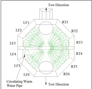
The occupant seating positions were numbered sequentially from LF1 to LF6 and from RT1 to RT6 respectively. Figures 2 and 3 show the seating arrangements for Phases 1 and 2 respectively. The four seating positions at the entrances of the raft were not used and left empty as emergency exits. In Phase 1, there were tests with one human subject and tests with eleven human subjects. Primary subjects are those instrumented to provide the necessary data for the study. Secondary subjects represent the other occupants who are there to create the microclimate inside the raft.
Figure 2. Phase 1 Seating Arrangements
The primary human subject always sat at the RT4 position and secondary subjects sat at the other positions shown in
Figure 2. A circulating warm water pipe was located at LF4 position. Warm water at about 40ºC was continuously circulated to the pipe by a pump and regulated by a water heater (Model 2.1IG, Space Saver, 1200W, 10L) on the Phase Tair [ºC] Twater [ºC] Wind [m/s] Wave Height [m] Leeway Speed [m/s] Test Duration [min] 1 19 16 NA Up to 1m 0, 0.5, 1 30 2 19 16 5 NA 0.5 135 3 5 5 5 NA 0.5 240 - 480
Copyright 2008 by ASME 4
carriage. A thermal blanket insulated the top of the pipe, so the heat it generated into the raft environment was minimized. The purpose of the pipe was to act as a stationary heat source for consistent measurement of heat conductance.
In Phase 2, tests were with 2 primary human subjects or with 2 primary subjects and 4 secondary subjects. The primary human subjects always sat in RT4 and LF4 positions, surrounded by secondary human subjects on both sides.
Figure 3. Phase 2 Seating Arrangements
In all the tests, the human subjects were wearing cotton T-shirts, cotton briefs, one-piece cotton coveralls and SOLAS life jackets. Neoprene foam gloves and boots protected their extremities. All the occupants were in a sitting position, with their buttocks in direct contact with the raft floor and their backs leaning against the floatation chambers of the raft, though generally the life jacket collar prevented direct contact between the subjects’ backs and the floatation chambers. The raft canopy was fully closed in all the tests.
Instrumentation
Two data acquisition systems were used in Phases 1 and 2 tests, one system was used to acquire signals from the human subjects and the life raft, and another system was used to acquire signals on the towing carriage. A bundle of cables, overhung in an umbilical cord, was used to carry the human subject and life raft signals back to the carriage. On the carriage, all the signals, except for heart rate data, from both acquisition systems were acquired by GDAC (GEDAP Data Acquisition and Control) client-server acquisition system, developed by National Research Council Canada, Institute for Ocean Technology. The sample rate for wave probes was 50 Hz. Data from all other sensors, except the heart rate monitors, was acquired at 1 Hz.
The heart rate of the primary human subjects was collected with a heart rate monitor (Model S-810i; PolarElectro, Kempele, Finland). The monitor was fastened to the chest of
the human subject using a plastic elastic band that came with the device. It acquired data every 5 seconds and transmitted them to a wrist logger wirelessly.
In Phase 1, five heat flow sensors (Model FR-025-TH44033-F6, Concept Engineering, CT, USA) were installed on the primary human subject (Figure 4).
Figure 4. Heat flow sensor locations on primary human subject in Phase 1
Each heat flow sensor has two channels, measuring the heat flow and temperature at the installation point on the human subject. Researchers used 3M Transpore tape to attach heat flow sensors to the subjects.
Instrumentation inside the raft included two heat flow sensors on the floor at RT4 and LF4 positions, floor pressure, and two air temperature sensors, one at the center and another near the entrance. During the test, the primary human subject sat on the heat flow sensor at RT4 position. The circulating warm water pipe was in direct contact with the heat flow sensor at LF4 position. On the carriage, two water temperature sensors and two wave encounter probes were installed.
In both phases, core body temperatures of the primary and secondary human subjects were recorded using rectal probes (Model 21090A, Philips). The insertion depth was 15 cm. In Phase 2, thirteen Concept Engineering heat flow sensors were used on each of the primary human subjects (Figure 5). Oxygen consumption, dioxide output, minute ventilation, and respiratory exchange ratio were continuously recorded with two automated breath-by-breath systems (K4B2, Cosmed,
Rome, Italie and Cortex Metamax, Leipzig, Germany) using a Nafion filter tube and a turbine flow meter (opto-electric). Prior to the experimental sessions, gas analyzers and volume were calibrated with medically certified calibration gases (15% O2 and 5% CO2) and with a 3-liter calibration syringe,
Copyright 2008 by ASME 5
electrochemical cells as O2 sensors and infrared technique for
CO2.
Figure 5. Heat flow sensor locations on primary human subject in Phase 2
Instrumentation inside the raft include five heat flow sensors on the floor, four heat flow sensors on the floatation chambers, four heat flow sensors on the canopy, two wind sensors, two air temperature sensors, and pressure of raft floatation tube and floor (Figures 6 to 8). There was one wind sensor outside the raft and two water temperature sensors on the carriage. Detail information regarding the raft internal and external environment was collected throughout the tests.
Figure 6. Heat flow sensors on raft floor and floatation chambers in Phase 2 tests
This raft floor design secures the inflatable floor with button-like fasteners that create depressions (dimples) in the raft floor and allow water to collect. Heat flow sensors were installed in raft floor areas with depression and without depression. The raft has two independent floatation chambers. Heat flow
sensors were installed on both the upper and lower floatation chambers.
Figure 7. Heat flow sensors on raft canopy in Phase 2 tests
Figure 8. Wind and air temperature sensors inside raft in Phase 2 tests
TEST PROGRAM AND METHODS
In Phase 1, each test was 30 minutes in duration. The tests were designed primarily to determine the raft floor heat conductance, by direct measurement of heat flux [W/m2] and temperature [ºC] using heat flow sensors.
The independent variables in Phase 1 include – • Leeway speed (0, 0.5 and 1 m/s)
• Waves
o No waves
o Regular waves with frequency 0.2 Hz and height 0.63 m
o Irregular waves with significant wave height of 0.25 m and 0.5 m
• Raft floor insulation o 0%,
o 50% (0.25 psi floor pressure)
o 100% (0.5 psi floor pressure as per manufacturer specified allowable working pressure upper range limit)
Copyright 2008 by ASME 6
The irregular wave spectrum used in the test program is a truncated sea spectrum representative of the Grand Banks of Canada. The target spectrum before truncation has a significant wave height of 3.3m (the average January sea state). The red line in Figure 9 illustrates this spectrum. Its frequencies ranged from 0.07 Hz to above 0.5 Hz. Since the wavemaker in the laboratory has an operational range above 0.2 Hz and a significant wave height of
approximately 0.5 m only, it was decided to truncate the wave spectrum at 0.2 Hz. The assumption was that the raft would simply ride a swell and that it would not affect the heat transfer mechanism. The blue line in Figure 9 shows the truncated spectrum. The truncated spectrum has a significant wave height of 0.5 m and 0.25 m at full and half span of the wave generator respectively.
Figure 9. Measured sea spectrum and truncated spectrum The heat conductance (or heat transfer coefficient) measured from the two heat flow sensors installed on the raft floor was computed as follows. water floor raft floor raft e Temperatur e Temperatur Flow Heat Coeff Transfer Heat − = where
Heat Flow raft floor = Heat flow measured by sensor
Temperature raft floor = Temperature measured by sensor
Temperature water = Tank water temperature measured
In Phase 2, each test was 135 minutes in duration. The aim was to characterize the thermal and metabolic rate responses of lightly dressed human subjects, who are exposed to mild cold conditions in a life raft. Based on the results of Phase 1, the tests in Phase 2 were designed to assess the following variables –
• Floor insulation (inflated or uninflated) • Clothing wetness (dry or wet)
• Few versus more occupants (2 primary subjects versus 2 primary subjects and 4 secondary subjects)
Eight instrumented human subjects (five males and three females) were exposed in pairs to four randomly assigned conditions inside the raft.
• Floor inflated, dry clothing (Idry) • Floor inflated, wet clothing (Iwet) • Floor uninflated, dry clothing (Udry) • Floor uninflated, wet clothing (Uwet)
These four conditions were repeated with an additional four secondary human subjects in the raft to examine the effect of multiple occupants on the thermal response of the two primary subjects. To maintain carbon dioxide concentration at a safe level during the trials (< 1000 ppm), a constant flow of fresh air was added. The flow rate of fresh air was 19 l/sec and 38 l/sec for two and six human subjects respectively. Factorial ANOVA tests were conducted to determine statistical significance in thermal responses of the primary subjects (p 0.05). No significant differences were found in thermal responses of the primary subjects in 2 and 6 subject tests. So, the data were pooled together for statistical analysis. RESULTS AND DISCUSSIONS
Effect of Leeway (Phase 1)
It is shown in Figures 10 and 11 that the heat conductance in calm water increases non-linearly at low leeway speed. Heat conductance appears to level off at some leeway speed between 0.5 m/s and 1 m/s. Since only three speeds were tested, 0 m/s, 0.5 m/s and 1 m/s, the exact speed where heat conductance levels off cannot be identified.
Figure 10. Effect of leeway on heat conductance derived from heat flow sensor under the circulating warm water pipe with 0% floor inflation
The data variation is much larger for human subjects than for the heated pipe but the same levelling off effect is observed. The larger variation is probably attributed to the fact that human subjects changed sitting postures every now and then, which in turn causes changes in contact area and heat conductance.
Effect of Leeway [Pipe]
0.0 10.0 20.0 30.0 40.0 50.0 60.0 70.0 80.0 0 0.2 0.4 0.6 0.8 1 1.2 Leeway (m/s) H ea t C onduc ta nc e ( W /m ^ 2C )
Calm Water 1 subject
Copyright 2008 by ASME 7
Figure 11. Effect of leeway on heat conductance derived from heat flow sensor under the primary human subject with 0% floor inflation
Effect of Wave Height (Phase 1)
Figure 12 displays that heat conductance increases with significant wave height at zero leeway speed. With leeway, this effect becomes less obvious.
Figure 12. Effect of wave height on heat conductance derived from heat flow sensor under the circulating warm water pipe The same effect is observed in Figure 13 with primary human subject. This indicates that wave height effect becomes less important with leeway and may be ignored as a first approximation to reduce the number of variables.
Figure 13. Effect of wave height on heat conductance derived from heat flow sensor under the primary human subject Effect of Floor Inflation (Phase 1)
In Figures 14 and 15, it is observed that the floor heat conductance is very high with 0% floor inflation. The heat conductance dropped by 5-6 times with 50% floor inflation. With 100% floor inflation, the heat conductance does not drop further considerably. This indicates that 50% floor inflation provides just as an effective thermal protection as 100% floor inflation.
Figure 14. Effect of floor inflation on heat conductance derived from heat flow sensor under the circulating warm water pipe
Effect of Leeway [Human Subject]
0.0 10.0 20.0 30.0 40.0 50.0 60.0 70.0 80.0 0 0.2 0.4 0.6 0.8 1 1.2 Leeway (m/s) H ea t C onduc ta nc e ( W /m ^ 2C )
Calm Water 1 subject Calm Water 12 subjects
Effect of Wave Height [Pipe]
0.0 10.0 20.0 30.0 40.0 50.0 60.0 70.0 80.0 0 0.2 0.4 0.6 0.8 1 1.2 Leeway (m/s) H ea t C o n d u cta n ce ( W /m ^ 2 C )
Calm Water 1 subject Irregular Hs0.25m 1 subject Irregular Hs0.5m 1 subject Regular Ht0.63m
Effect of Wave Height [Human Subject]
0.0 10.0 20.0 30.0 40.0 50.0 60.0 70.0 80.0 0 0.2 0.4 0.6 0.8 1 1.2 Leeway (m/s) H ea t C o n d u ct an ce (W /m ^ 2 C )
Calm Water 1 subject Irregular Hs0.25m 1 subject Irregular Hs0.5m 1 subject Regular Ht0.63m
Effect of Floor Inflation [Pipe]
0.0 10.0 20.0 30.0 40.0 50.0 60.0 70.0 80.0 0 0.2 0.4 0.6 0.8 1 1.2 Leeway (m/s) H ea t Conduc ta nc e (W /m ^ 2C)
Calm Water 1 subject 0 % Calm Water 1 subject 100% Irregular Hs0.25 1 subject 50% Irregular Hs0.25 1 subject 100%
Copyright 2008 by ASME 8
Figure 15. Effect of floor inflation on heat conductance derived from heat flow sensor under the primary human subject
Carbon Dioxide Concentration Inside Life Raft (Phase 1) In Phase 1, 11-person test, carbon dioxide concentration was observed to reach an uncomfortable level, over 5000 ppm, in less than 1 hour inside the raft with closed canopy and no active ventilation (see Figure 16). The high concentration of carbon dioxide observed is consistent with that reported by Germany (IMO, 2002), in which they showed large decrease in oxygen accompanied by large increase in carbon dioxide within an hour.
Figure 16. Life raft microclimate
The carbon dioxide gas sensor saturated after it reached 5000 ppm. Since there was no real-time monitoring of carbon dioxide in this phase, the high concentration was not
recognized until the subjects complained about the air quality ½ hour later. The American Conference of Governmental Industrial Hygienists (ACGIH) has recommended carbon dioxide a Threshold Limit Value, Time Weighted Average (TLV-TWA)1 of 5,000 ppm and a Threshold Limit Value, Short Term Exposure Limit (TLV-STEL)2 of 30,000 ppm. Subject Core Body Temperature and Heat Generated by Occupants (Phase 1)
It was speculated that the microclimate inside an enclosed life raft, with canopy entrance closed, no active ventilation, multiple occupants and floor inflated would retain heat generated by the occupants. The elevated temperature may help occupants to reduce heat loss, maintain a steady core body temperature or may even cause a rising body temperature.
In the 11-person test, all four subjects with rectal probe lost core body temperature. This seems to indicate that the heat generated by the occupants was not sufficient to keep everyone’s core body temperature from dropping. Core temperature of male subjects dropped by 0.66ºC and 0.51ºC respectively in 2 hours. Core temperature of female subjects dropped by 1.16ºC and 1.01ºC respectively in the same time duration. Further analysis is required to define if the body heat content of the subjects was affected by the exposures or if a shift in blood volume and a local cooling in the buttock areas caused the observed drop in rectal temperature.
Also, regardless of whether the floor was inflated or deflated; 11 occupants or 1 occupant; regular or irregular wave condition; floor dry or wet, the core body temperature of the subjects decreased over the 30-minute test period. There were only three exceptions. The increase observed was so small, in the range of 0.04ºC, that we could not conclude definitely that the elevated temperature from having multiple occupants helped them to reduce heat loss. The possibility of occupants keeping themselves warm through body heat generated was studied in more detail in Phases 2 and 3 with longer duration tests.
1
TLV-TWA (Threshold Limit Value, Time Weighted Average) is the average concentration under which most people can work consistently for eight hours, day in, day out, with no harmful effects. Gas or vapors are expressed in Parts Per Million (ppm), while solids, mist or floating dust particles are expressed in Milligrams Per Cubic Meter (mg/m3).
2
TLV-STEL (Threshold Limit Value, Short Term Exposure Limit) is the maximum concentration permitted for a continuous 15-minute exposure period. There may be a maximum of four such periods per day, with at least 60 minutes between exposure periods, and provided the daily TLV-TWA is not exceeded.
Effect of Floor Inflation [Human Subject]
0.0 10.0 20.0 30.0 40.0 50.0 60.0 70.0 80.0 0 0.2 0.4 0.6 0.8 1 1.2 Leeway (m/s) H ea t C onduc ta nc e (W /m ^ 2C )
Calm Water 1 subject 0 % Calm Water 1 subject 100% Irregular Hs0.25 1 subject 50% Irregular Hs0.25 1 subject 100%
Liferaft Microclimate - 11 Occupants
0 1000 2000 3000 4000 5000 6000 0: 00 0: 10 0: 20 0: 30 0: 40 0: 50 1: 00 1: 10 1: 20 1: 30 Elapsed Time (hh:mm) CO 2 Conc ent ra ti on (ppm ) 0 10 20 30 40 50 60 70 80 90 100 T em p (de g C) a nd RH (%) CO2 PPM TEMP °C RH %
Copyright 2008 by ASME 9
Subject Core Body Temperature and Heat Generated by Occupants (Phase 2)
The key results from Phase 2 are summarized in Table 2. Details of experimental setup, analysis and results can be found in Ducharme et al. (2007).
Tsk [°C] HF [W/m2] Tre [°C] MR [W] Baseline 33.3±0.6 58±8 37.1±0.3 Idry 33.5±0.8 52.4±5.1 36.4±0.4 111.0±9.0 Iwet 30.9±1.1 64.9±11.0 36.5±0.4 122.0±8.4 Udry 32.1±0.7 55.8±8.9 36.0±0.6 117.6±9.0 Uwet 30.0±1.0 67.4±11.2 36.0±0.6 131.8±9.6
Table 2. Key primary human subject results from Phase 2 tests Where
Tsk = Mean skin temperatures HF = Mean skin heat loss Tre = Rectal temperatures MR = Metabolic rate
At the end of the 135-minute tests, it was observed that the subject mean skin temperatures (Tsk) were significantly lowered for all conditions, except for the Idry condition. Mean skin heat loss (HF) increased significantly only in the wet conditions. Rectal temperatures (Tre), which is a measure of core body temperature, decreased in all conditions. The decrease was significantly more in floor uninflated conditions. Metabolic rates of the subjects were not significantly different among conditions even though it tended to increase more in floor uninflated and wet clothing condition (Uwet).
The clothing wetness had no significant effect on the magnitude of rectal temperature cooling since Idry and Iwet conditions have the same temperature at the end of the exposure and similarly for Udry and Uwet conditions. The mean decrease in rectal temperatures was 1.1±0.5°C and 0.7±0.3°C for in Udry and Idry conditions respectively, despite that there was no significant heat loss in the dry conditions when compare to the baseline. It appears that floor inflation is the determining factor for the magnitude of decrease in rectal temperature.
CONCLUSIONS
In Phase 1, the following conclusions were drawn from the test results:
1. Heat conductance increases non-linearly with leeway. It appears to level off above 0.5 m/s leeway speed. 2. At zero leeway speed, heat conductance increases with
significant wave height. With leeway, this effect is less obvious. The results showed that wave height effect is less important with leeway and may be ignored as a first approximation to reduce the number of environmental variables. It is believed that as long as the boundary layer near the raft surface providing the thermal insulation is broken up, it does not matter if the mechanism is caused by leeway or wave action. Once the boundary layer is
broken, the heat conductance of the raft will increase. 3. Heat conductance decreases considerably with floor
inflation. Heat conductance is about the same with floor inflated 50% and 100%.
4. In the 11-person test, all four subjects with a rectal probe lost core body temperature. This seems to indicate that the heat generated by the occupants may not be sufficient to keep everyone’s core body temperature from dropping. Core temperature of male subjects dropped by 0.66
°
C and 0.51°
C respectively in 2 hours. Core temperature of female subjects droppedby 1.16°
C and 1.01°
Crespectively in the same time duration. This observation was further investigated in Phases 2 and 3.
5. In the 11-person test, CO2 concentration reached an
uncomfortable level (over 5000 ppm) in less than an hour inside the raft with closed canopy and no active
ventilation. The relative humidity reached over 75% during that time duration and climbing steadily to 85% in less than 2 hours. Interior raft temperature increased from 23.6
°
C to 28°
C. This elevated CO2 concentration insidethe raft suggests that active ventilation at a known rate is required to keep the CO2 at a safe controlled level when
longer duration tests are to be conducted.
In Phase 2, the following conclusions were drawn from the test results:
1. During exposure in a mild cold environment inside a closed life raft, the wetness of the clothing worn by the occupants and the absence of floor insulation will both significantly decrease the mean skin temperatures of the occupants. However, only the clothing wetness will increase the heat loss from the subjects.
2. The thermal stress induced by the different test conditions was not sufficient to significantly and consistently increase the metabolic rate of the occupants through shivering. Despite the mild responses to cold during the exposures (Tsk above 30°C, HF increased by < 15%; no definitive shivering), Tre significantly decreased for all conditions tested by as much as 1.1°C. This was
particularly the case for the condition Udry where the Tsk was on average 32°C by the end of the exposure, and both HF and MR had not increased from baseline.
If the observed rate of decrease in Tre for that condition is extrapolated, it could be predicted that the occupants would not survive for more than 18 hours inside a liferaft originally designed for a multi-days survival in much colder environments. It is concluded that to estimate survival time inside a liferaft, or to evaluate the thermal protection of a liferaft, the short-term decrease in Tre from the occupants should not be the only or the primary factor taken into consideration. It is necessary to assess if the rectal temperature is still a true indicator of the core body temperature when localized cooling is taking place around the buttock. It is also desirable to have test
Copyright 2008 by ASME 10
conditions that could induce shivering, so as to assess if the heat loss can be offset by the heat produced. In addition, longer test duration will help to determine if the body heat storage is decreasing over time. All of these were addressed in Phase 3.
3. Since there were no noticeable differences in the thermal responses between the conditions involving 2 versus 6 occupants, it was not apparent that heat generated from multiple occupants helped them to reduce heat loss. The effect of multiple occupants was further assessed in Phase 3.
ACKNOWLEDGEMENT
The authors would like to thank SAR New Initiatives Fund and Transport Canada for their financial support on this project.
REFERENCES
1. American Conference of Governmental Industrial Hygienists, ACGIH (2004) Threshold Limit Values for Chemical Substances and Physical Agents and Biological Exposure Indices.
2. DuCharme, M.B., Evely, K.A., Basset, F., MacKinnon, S., Kuczora, A., Boone, J. and Mak, L.M. (2007), “Effect of Wetness and Floor Insulation on the Thermal
Responses During Cold Exposure in a Life Raft”, Proceedings of 12th International Conference on Environmental Ergonomics, Piran, Slovenia.
3. IMO (1996), Resolution MSC.48(66), “International Life-Saving Appliance (LSA) Code”, International Maritime Organization (IMO) Maritime Safety Committee, 66th session, June 1996.
4. IMO (2002), “Microclimate in Totally Enclosed Survival Craft”, International Maritime Organization (IMO) Sub-Committee on Ship Design and Equipment, 45th session, Agenda Item 26, DE 45/INF.11, Submitted by Germany, January 2002.
5. Tikuisis, P and Keefe, A (2005), “Stochastic and life raft boarding predictions in the Cold Exposure Survival Model (CESM v3.0)”, Defence R&D Canada – Toronto, TR-2005-097.