Publisher’s version / Version de l'éditeur:
Vous avez des questions? Nous pouvons vous aider. Pour communiquer directement avec un auteur, consultez
la première page de la revue dans laquelle son article a été publié afin de trouver ses coordonnées. Si vous n’arrivez pas à les repérer, communiquez avec nous à [email protected].
Questions? Contact the NRC Publications Archive team at
[email protected]. If you wish to email the authors directly, please see the first page of the publication for their contact information.
https://publications-cnrc.canada.ca/fra/droits
L’accès à ce site Web et l’utilisation de son contenu sont assujettis aux conditions présentées dans le site LISEZ CES CONDITIONS ATTENTIVEMENT AVANT D’UTILISER CE SITE WEB.
18th International Symposium on Ice [Proceedings], 2006
READ THESE TERMS AND CONDITIONS CAREFULLY BEFORE USING THIS WEBSITE.
https://nrc-publications.canada.ca/eng/copyright
NRC Publications Archive Record / Notice des Archives des publications du CNRC : https://nrc-publications.canada.ca/eng/view/object/?id=2387254e-ba7d-4dcb-abb9-67c2e2813f3c https://publications-cnrc.canada.ca/fra/voir/objet/?id=2387254e-ba7d-4dcb-abb9-67c2e2813f3c
NRC Publications Archive
Archives des publications du CNRC
This publication could be one of several versions: author’s original, accepted manuscript or the publisher’s version. / La version de cette publication peut être l’une des suivantes : la version prépublication de l’auteur, la version acceptée du manuscrit ou la version de l’éditeur.
Access and use of this website and the material on it are subject to the Terms and Conditions set forth at
Discrete element modeling of ship manoeuvring in ice
DISCRETE ELEMENT MODELING OF SHIP MANOEUVRING IN ICE
Michael Lau
Institute for Ocean Technology, National Research Council of Canada, St. John’s, Newfoundland, Canada
ABSTRACT
This paper reports on recent numerical modeling and comparison with physical model experiments conducted in the Institute for Ocean Technology (IOT) of the National Research Council of Canada (http://iot-ito.nrc-cnrc.gc.ca/). The numerical study was carried out using DECICE, a commercial discrete element code. The discrete element formulation has been benchmarked and verified against experimental data from a variety of sources. The numerical simulations conducted in this work include a 1:21 scale model of the Canadian Icebreaker, Terry Fox, advancing and turning in level ice conditions. The physical experiments were carried out in IOT’s ice tank using a Planar Motion Mechanism (PMM). Analysis of the numerical results shows the effects of ice conditions and ship motions on the computed forces and moments. Comparisons between the numerical results and experimental data provided a validation of the numerical model.
KEY WORDS: Numerical simulations; Manoeuvring; Sea ice; Model tests; Discrete element method
INTRODUCTION
Recent development of offshore oil and gas reserves in several countries, together with economic studies to increase transportation through the Arctic, has led to a renewed interest in the manoeuvrability of vessels in ice. Despite a sizeable volume of work, there is not yet a universally accepted method of predicting ship performance in ice. The Institute for Ocean Technology (IOT) of the National Research Council of Canada ( http://www.iot-ito.nrc-cnrc.gc.ca/) is currently conducting physical, numerical, and mathematical modeling of ship manoeuvring characteristics in ice, as part of a larger effort to develop reliable modeling techniques to assist in the design of new ice-worthy vessels and in the simulation of their navigating characteristics. The objective is to develop a physical representation of the complex interaction processes of a ship manoeuvring in ice and to build mathematical and numerical models to satisfactorily predict its performance. In turn, these models will provide a tool for ship designers to use as part of the assessment of ship navigation in ice infested routes. It can also be incorporated into marine simulators to train mariners, or into automatic ship control systems for better ship manoeuvring.
Lau et al. (2006) have presented the numerical modeling of ship navigation performances in pack ice, where ice impact and clearing dominates the interaction. This paper presents results of the numerical analysis on ship manoeuvring in level ice conditions with an added element of complexity - ice failure. Analysis of the numerical results shows the effects of ice conditions and ship motions on the computed forces and moments. Comparisons between the numerical results and experimental data provided a validation of the numerical model. Conclusions are made and recommendations for future works are provided.
NUMERICAL SIMULATIONS
With the advance of computing technology, large simulations are possible even with a small personal computer. Numerical experiments can be useful for understanding complex phenomenon and provide an attractive complementary tool to full-scale measurements and model tests at a fraction of the cost. We are in the process of upgrading a three-dimensional version of the discrete element code DECICE (Hocking et al., 1987) for general ships and structures in ice and wave simulations, including the more complicated tactical operations in ice infested environments, i.e., ships at transit and at berth, iceberg towing, deep sea mooring, seabed scouring, fishing boats and survival craft performance in severe wave and ice environments, etc. Such a numerical tool is also useful to obtain detailed information that cannot be obtained experimentally, i.e. load distribution, energy and stress states.
The computer program was developed for solving complex solid mechanics problems involving multiple interacting bodies undergoing fracture. The versatility of DECICE in modelling ice-related problems has been demonstrated in a number of recent works by the author and his colleagues, including ice interactions with a bridge pier (Lau, 2001), jamming of floes at bridge piers (Lau, 1994), pack ice forces on structures from discrete floes (Lau et al., 1996), modelling of rubble shear properties (Lau, 1999), rubble loads exerted on multifaceted cones (Lau, 1999), ridge keel resistance during ice scouring (Lau et al., 2000), and the performance of survival craft in pack ice (Lau et al., 2006).
The DECICE computer code is based upon a dynamic equilibrium explicit time stepping formulation and centres around a sophisticated housekeeping logic. The logic is specially designed to track the behaviour and response of a large number of deformable bodies efficiently. The bodies may be in contact with each other while undergoing large non-linear deformation and discrete fracturing. The algorithmic details of DECICE are described in Hocking et al. (1987). General Model Description
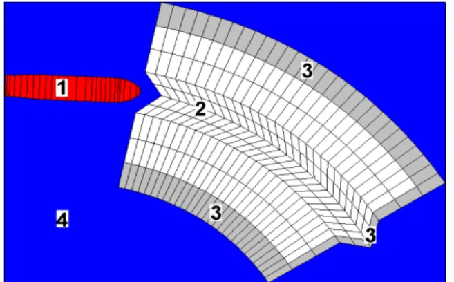
The methodology and modeling assumptions used in the interaction model are described with a typical geometrical idealization shown in Figure 1. The discrete element model consists of the following components: A ship model representing the Terry Fox with a prescribed turning or advancing motion; a free-floating level ice plate modeled with 3D plate bending elements; fixed blocks at the rear and sides of the ice edge, to model the fixed boundary condition; and a water foundation.
The Terry Fox was numerically modeled by a rigid motion element (ME) that allows motion in six degrees of freedom. Numerical ballast, trim, decay, and open water resistance tests were performed to ensure that the numerical model results compared favourably with those measured in the model tests. A standard procedure for the above hydrostatic and hydrodynamic matching is given in Lau et al. (2006). For these tests, planar motion of the model was prescribed to simulate that of the model test.
The ice plate consisted of three zones (a central channel and the ice area at two sides) with each zone further subdivided into a number of three-dimensional plate bending
elements. Elements in the central channel had sides approximately the length of the measured piece size to simulate the observed ice-breaking pattern. The sensitivity of ice loads on element size was not investigated in these simulations; however, the element length to piece size relationship used was shown to be satisfactory in simulating the interaction forces in this and a similar study by Lau (2001).
The level ice plate was resting on a water foundation. The buoyancy forces and moments acting on each element were calculated by integrating over the wetted surface of each element. For these simulations, the hydrodynamic damping of the ship was not included. Hence, the computed load represented the ice related components, and the measured open water resistance was subtracted from the total load in ice before comparison with the simulated result.
Total run distance for each simulation was set to double the ship length to allow sufficient time for the development of steady state ice loads. The distance was estimated based on experience from previous model tests, and proved to be sufficient for a preliminary simulation. The open channel width was set according to test measurements. The width of the side plate was chosen to be at least three times greater than the characteristic length, lc, of the ice sheet to properly
simulate an ice sheet of infinite extent by a finite boundary. The length of ice channel was set to double the ship length plus three times lc to maintain sufficient distance from the end blocks at
the end of the simulation.
For these simulations, a hybrid simple deformable 3-D plate-bending element of the Mindlin type (SDFE) was used. The approach used to derive this type of element is described by Mustoe et al. (1987). The ice sheet was modelled as an isotropic elastic brittle material with Mohr-Coulomb failure criteria and tension cut-off. Compressive, shear, tensile, and flexural modes of brittle failure can occur. The elements are fractured along inter-element mesh-lines in the direction given by the fracture criteria and the prevailing stress conditions.
A penalty function approach forms the basis of the contact force generation algorithm implemented in DECICE. A series of stiff contact springs were distributed between the contact interfaces to generate a distribution of contact loading for the two bodies. The spring stiffness was selected to enforce the compatibility condition between elements and give a reasonable time
Figure 1: Geometrical idealization of ship maneuvering model used in DECICE simulation (1 – Rigid moving object; 2 – Free-floating ice plate; 3 – Rigid Boundary; 4 – Water Foundation).
step length. It was computed from the stiffness of adjacent elements to limit the interface displacement to less than 0.01% of the adjacent element deformations. The normal and tangential inter-element stiffness were chosen equal. The Coulomb friction law limits the magnitude of the shear interaction force between discrete bodies. The external coefficient of ice-ice cohesion was set to zero and the external ice-ice friction coefficient was set to 0.4. The friction between the ice and the model hull was measured and set to 0.01.
Damping was needed to damp the rigid body motions (mass damping) and the internal deformations of SDFE’s (internal damping). The fundamental frequencies of rigid body and internal deformation modes of vibration were obtained from a free vibration simulation, in which a vertical impulse was applied on the undamped ice system. The amount of damping in the system was not measured experimentally. Arbitrary values of 5% and 100% critical damping were chosen for the element mass and internal damping, respectively.
The impact of ice on a ship hull involves localized crushing of the ice edge at the immediate contact zone followed by flexural failure. Therefore, a more realistic simulation of the ice failure process would require proper modelling of the localized crushing. This modelling requires a substantial modification of the computer code and is beyond the scope of this study. In the present study, only the existing capabilities of DECICE were employed.
The discrete element modeling requires contact springs to transfer loads between elements. The effective normal and tangential spring stiffness of 3x10⁶ N/m2 was chosen for the present simulation. A preliminary simulation with an advancing speed of 0.3 m/s and a spring stiffness ranging from 3x10⁵ N/m2 to 3x10⁷ N/m2 to assess its effect on yaw moment experienced by the model while performing the 10 m and 50 m turns showed a negligible influence of spring stiffness on the resistance within the range of stiffness variation.
MODEL TESTS
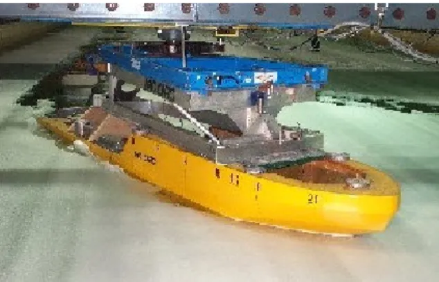
The experiments were carried out in CD-EG/AD/S ice with a 1:21.8 scaled model of the Canadian Coast Guard’s icebreaker, Terry Fox (IOT Model # 417). The model was mounted to the towing carriage through a PMM (Planar Motion Mechanism) at the model’s centre of gravity (see Figure 2), and towed at a controlled planar motion through a level ice sheet. In each run, tow force, turning moment, and ship motions were measured. The model surface was finished to a friction coefficient of 0.01 with Dupont’s Imron paint.
The test matrix for the experimental program is summarized in Table 1. The ice sheets had a target ice thickness of 40 mm and a target flexural strength of 35 kPa. For each ice sheet, flexural, compressive and shear strengths were measured frequently throughout the test period. Turning circle manoeuvring and towed resistance tests were conducted. The constant radius manoeuvre was conducted with two turning radii (50 m and 10 m). All tests were conducted with model velocity ranging from 0.02 m/s to 0.6 m/s. These velocities corresponded with a yaw rate ranging from –0.02 deg/s to –3.4 deg/s. Concurrent to the testing in ice, manoeuvres in open water were also conducted.
Preliminary analysis was performed to understand the observed trend (Lau and Derradji-Aouat; 2004) via mathematical modeling. (See Figure 3.) It is believed that the moment at zero yaw rate was mainly contributed by velocity independent ice breaking and submergence components, and
the slope was determined by velocity dependent ice clearing and the open water components. The readers are referred to Lau and Derradji-Aouat (2004) for details.
SIMULATION RESULTS AND
DISCUSSIONS
A total of 14 simulations were set up according to the mechanical properties of the ice and the preset ship path for each test run: 11 for ship turning and 3 for ship advancing. An error in the motion controlling software led to a small un-intended drift angle of the model orientation up to -3.8 degrees. The drift angle measured in each test was used in the simulation.
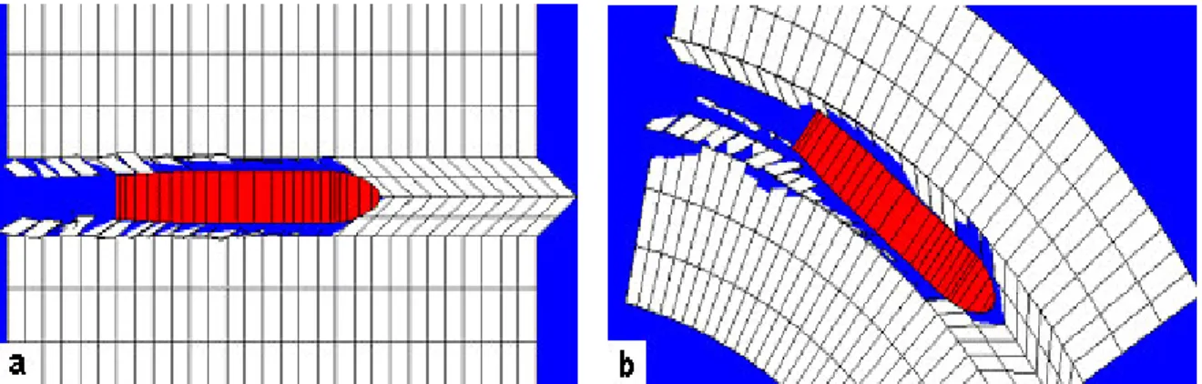
Figure 4 shows snapshots of a typical simulation for ship advancing and for ship turning at the 10 m radius. The interaction consisted of a series of
breaking of intact ice and the subsequent submergence and clearing of the broken ice pieces typical of those observed in the model tests. The broken ice generated at both sides of the bow clear from the respective side as shown in Figure 5. A typical moment time history of the 50 m and 10 m runs are given in Figures 6a and 6b, respectively.
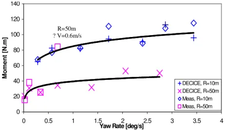
A plot of predicted versus measured loads is shown in Figures 7a and 7b for the resistance and manoeuvring runs, respectively. Despite the simplicity of the problem treatment, a good agreement exists between the computed loads and the experimental measurements, except one data point corresponding to R = 50 m and V = 0.6 m/s. The computed and measured yaw moments are re-plotted in Figure 8 against yaw rate to further assess the validity of the data point in question. Additional runs were conducted to better define the trends predicted by the numerical model. The computation simulates the trend for R=10 m very well, and in the case of the R=50 m, the first three data points with the lower model speeds give good comparison. The measured value of the data point in question seems not to follow the general trend predicted. It is possible that the measurements for that run were spurious; however, additional data are needed to confirm that.
Figure 2: Terry Fox model attached to the PMM.
Table 1: Matrix of the test program. Turning Radius, R (m) ∞ 50 10 Model Speed, V (m/s) 0.02~0.6 Yaw Rate, γ (deg/s) 0.02~ 0.34
Ice Thickness (mm) 40
Ice Strength (kPa) 35
Figure 3: Measured yaw moments versus yaw rate. 0 20 40 60 80 100 120 140 0 0.5 1 1.5 2 2.5 3 3.5 4 Yaw Rate (deg/s)
M o m e n t (N .m ) R=10m R=50m Linear (R=10m) Linear (R=50m)
Figure 4: (a) Snapshot of a typical simulation for the ship advancing and (b) for the ship turning at 10 m radius.
Figure 6: Typical moment time histories for (a) R=10 m and (b) R=50 m runs.
Figure 5: Broken ice clearing for (a) straight advancement and (b) 10 m turning circle radius. 0 10 20 30 40 50 60 0 20 40 60 Measured Resistance [N] P re d ic te d R e s is ta n c e [ N ] Resistance Runs 1:1 fit 0 20 40 60 80 100 120 140 0 50 100 150 Measured Moment [N.m] P re d ic te d M o m e n t [N .m ] R=10m R=50m 1:1 fit
Figure 7: Predicted versus measured resistance in the resistance runs (a: left) and predicted versus measured moment in the turning circle runs (b: right).
? R=50m V=0.6m/s
CONCLUSION AND FURTHER WORK
This paper presents the results of numerical analysis on ship manoeuvring in level ice conditions. The technical approach and methodology employed are briefly described. The validity of the numerical model was assessed by comparing its predictions to measurements from model tests. Analysis of the numerical results shows the effects of ice conditions and ship motions on the computed forces and moments. Comparisons between the numerical results and experimental data provided a validation of the numerical model. Despite the simplicity of the problem treatment, the analysis gave a good prediction.
The analysis presented in this paper has been significantly simplified. The elements were not allowed to fail and generate new elements. The crack pattern was imposed according to observation from model tests. This does not allow the ship to create the broken channel according to the prevailing ship motions. Furthermore, a planar motion was also prescribed to the ship in these simulations. Efforts are underway to conduct further simulations to refine the numerical model by: (1) allowing failure of individual ice elements, hence, an arbitrary channel can be created by the ship’s prevailing motions, and (2) modeling self propulsion test condition, hence, allowing more realistic ship motions. Details of the ice breaking and clearing processes occurring simultaneously along the hull and the resulting load distributions will also be examined.
ACKNOWLEDGEMENTS
The investigations presented in this paper were partially funded by the Atlantic Innovation Fund through the Marine Institute, Newfoundland. Bruce Quinton assisted in the numerical simulation. Their assistance is gladly acknowledged.
0 20 40 60 80 100 120 140 0 0.5 1 1.5 2 2.5 3 3.5 4
Yaw Rate [deg/s]
M o m e n t [N .m ] DECICE, R=10m DECICE, R=50m Meas, R=10m Meas, R=50m
Figure 8: Plot of computed and measured yaw moments versus yaw rate.
R=50m ? V=0.6m/s
REFERENCES
Hocking, G., Mustoe, G.G.W., and Williams, J.R. (1987), “Dynamic Analysis for Generalized Three-Dimensional Contact and Fracturing of Multiple Bodies”, NUMETA ‘87, Balkema Publications, Swansea, UK.
Lau, M. (2001), “A Three Dimensional Discrete Element Simulation of Ice Sheet Impacting a 60-Degree Conical Structure,” Proceedings of the 16th International Conference on Port and Ocean Engineering under Arctic Conditions, POAC’01, Ottawa, Ontario, Vol. 1, pp. 431-440.
Lau, M. (1999), “Ice Forces on a Faceted Cone due to the Passage of a Level Ice Field,” Ph.D. Thesis, Memorial University of Newfoundland, St. John’s, NL, Canada.
Lau, M. (1994), “Pack Ice Jamming Simulation: DECICE2D,” National Research Council of Canada, Institute for Marine Dynamics, St. John's, Newfoundland.
Lau, M. and Derradji-Aouat, A. (2004), “Preliminary Modeling of Ship Maneuvering in Ice”, 25th Symposium on Naval Hydrodynamics, St. John’s, Newfoundland.
Lau, M., McKenna, R.F., Spencer, D., Walker, D. and Crocker, G. B. (1996), “Modelling Pack Ice Forces on Structures from Discrete Floes,” Marineering Ltd., St. John's, NF, Canada. Lau, M., Phillips, R., McKenna, R.F., and Jones, S.J. (2000), “Discrete Element Simulation of
Ridge Keel Resistance during Scouring: A Preliminary Study,” Proc. 2nd Ice Scour & Arctic
Marine Pipelines Workshop, Mombetsu, Hokkaido, Japan.
Lau, M., Simões Ré, A., and Veitch, B. (2006), “Performance of Survival Craft in Ice Environments,” International Conference and Exhibition on Performance of Ships and
Structures in Ice, July 16-19, 2006, Banff, Alberta, Canada.
Mustoe, G.G.W., Williams, J.R., Hocking, G., and Worgen, K. (1987), “Penetration and Fracturing of Brittle Plates under Dynamic Impact,” NUMETA '87, Balkema Publications, July 6-10, Swansea, U.K.