Biologically-inspired Robots for Stage Performance
byWei Dong
Bachelor of Science, Applied Physics
Nanjing University of Science & Technology, 2000 Master of Engineering, Manufacturing Massachusetts Institute of Technology, 2006
MASSACHUSETTS INSTITUTE OF TECHNOLOCY
SEP 1 4 201
LIBRARIES
ARCHNES
SUBMITTED TO THE PROGRAM IN MEDIA ARTS AND SCIENCES, SCHOOL OF ARCHITECTURE AND PLANNING,
IN PARTIAL FULFILLMENT OF THE REQUIREMENTS FOR THE DEGREE OF
MASTER OF SCIENCE IN MEDIA ARTS AND SCIENCES AT THE
MASSACHUSETTS INSTITUTE OF TECHNOLOGY SEPTEMBER 2010
0 2010 Massachusetts Institute of Technology All rights reserved
-L
Signature of Author: ...C ertified by: ...
j
..
...
Program in Media Arts and Sciences August 6, 2010
Tod Machover Professor of Music and Media Program in Media Arts and Sciences Thesis Supervisor
A ccep ted b y: ... ... .. ... ... Pattie Maes Associate Professor of Media Technology Chair, Departmental Committee on Graduate Studies Program in Media Arts and Sciences
Biologically-inspired Robots for Stage Performance
by
Wei Dong
Submitted to the Media Laboratory on August 15, 2010 in Partial Fulfillment of the
Requirements for the Degree of Master of Science in Media Arts and Sciences
ABSTRACT
Stage performances present many challenges and opportunities in the field of robotics. Onstage robots not only have to function flawlessly, they must interact convincingly with their human counterparts and adhere to a rigid timeline. The scope of this work is to create set pieces that look and behave like organic entities for the production of Tod Machover's new opera, Death and the Powers. With a set of design rules and techniques, I have developed the mechanical and control systems, including their interactive behavior, for several performance-ready robots. A six-legged walking robot and transformable robot were first built to verify the adopted design methodology prior to the prototyping of onstage robots. In addition, the robots were certified as performance-ready according to four criteria: the visual appearance, the overall functionality, the quality of movement, and the fluency of human-robot interaction. Two robots were successfully built and tested for use in the opera of Death and the Powers.
Thesis Supervisor: Tod Machover Title: Professor of Music and Media
Biologically-inspired Robots for Stage Performance
byWei Dong
The following people served as readers for this thesis:
/7 Thesis Reader: ...
Cynthia Breazeal Associate Professor of Media Arts and Sciences Program in Media Arts and Sciences
A
T h esis R ead er: ... ... Alex McDowell, RDI
Production Designer Visiting Artist MIT Media Laboratory Adjunt Professor School of Cinematic Arts University of Southern California
ACKNOWLEDGEMENTS
The author wishes to express sincere appreciation to Professor Tod Machover for his assistance in defining and solving the problem. He not only explained a lot of concepts to the team, but more importantly encouraged us to explore new approaches. He always made time to meet with me, and kept my work on the right track.
Thanks to Professor Cynthia Breazeal and William
J.
Mitchell for inspiring me, providing reference materials, and taking the time to review my thesis. Thanks to Alex McDowell for taking the trip all the way to Boston to review the progress and to point out the areas that needed improvements.Thanks also to my labmates who always supported me throughout the project. They are Andy Cavatorta, Bob Hsiung, Elena Naomi Jessop, Noah Feehan, Paula Countouris, and Peter Torpey. They are the driving force behind the problem solving and robot development efforts. Without them, my project would have fewer results to provide.
TABLE OF CONTENTS
CH A PTER 1 IN TR O D U C TIO N ... 7
1. 1 GENERAL BACKGROUND ... 7
1.2 THE OPERA - D EATH AND THE POWERS... 8
1.3 OBJECTIVE AND SCOPE... 8
1.4 THESIS OUTLINE... 9 CH APTER 2 M ETH O D O LO G Y ... 10 2.1 INTRODUCTION...10 2.2 BIOLOGICALLY-INSPIRED ROBOTS ... 10 2.3 D ESIGN W ORKFLOW ... 11 2.4 M ECHANICAL SYSTEM ... 12 2.5 ELECTRICAL SYSTEM ... 14 2.6 OTHER CONCERNS ... 15 2.7 SUMM ARY ... 16
CHAPTER 3 A W ALKING ROBOT - MEI-MEI...17
3.1 INTRODUCTION...17
3.2 M ECHANICAL SYSTEM ... 17
3.3 ELECTRICAL SYSTEM ... 21
3.4 LESSONS LEARNED...22
3.5 SUMMARY ... 24
CHAPTER 4 A TRANSFORMABLE ROBOT - SOFA ... 25
4.1 INTRODUCTION...25
4.2 M ECHANICAL SYSTEM ... 25
4.3 ELECTRICAL SYSTEM ... 31
4.4 LESSONS LEARNED...35
4.5 SUM MARY ... 36
CHAPTER 5 IMPLEMENTATION OF STAGE ELEMENTS...37
5.1 INTRODUCTION ... 37
5.2 LIGHTING ... 37
5.3 V ISUAL EFFECTS ... 38
5.4 SOUND EFFECTS ... 40
5.5 SUM M ARY ... 41
CHAPTER 6 CONCLUSION AND FUTURE WORK...42
R EFER EN C ES ... 46
APPENDIX A FIRMWARE OF SOFA CONTROLLER ... 48
APPENDIX B FIRMWARE INTERFACING WITH ACCELEROMETER ... 53
LIST OF FIGURES
FIGURE 2.1 PRODUCT DESIGN WORKFLOW ... 12
FIGURE 3.1 LEONARDO DA VINCI'S MECHANICAL LION ANDTHEO JANSEN'S BEACH ANIMALS.. 18
FIGURE 3.2 KINEMATIC ANALYSIS OF FOUR-BAR LINKAGE... 19
FIGURE 3.3 R OBOT DRIVEN SYSTEM ... 20
FIGURE 3.4 M EI-M EI ROBOT AND ITS LEGS ... 20
FIGURE 3.5 PI) ALGORITHM USED IN POSITION CONTROL ... 21
FIGURE 4.1 DESIGN CANDIDATES OF BIOLOGICALLY-INSPIRED ROBOTS ... 26
FIGURE 4.2 DETAILS OF DESIGN CANDIDATE No. 6... 27
FIGURE 4.3 COMPUTER GRAPHIC MODEL OF THE SOFA... 27
FIGURE 4.4 SCALE MODEL OF THE SOFA ROBOT ... 28
FIGURE 4.5 GEOMETRY SKETCH DRAWING OF THE SOFA ROBOT ... 29
FIGURE 4.6 ANSYS ANALYSIS OF TOP PLATE ... 30
FIGURE 4.7 RENDERING MODEL AND FULL-SCALE PROTOTYPE OF THE SOFA ROBOT... 31
FIGURE 4.8 DRIVING WAVES FOR ROTATIONAL MOTION... 32
FIGURE 4.9 MEASUREMENT ERRORS OF THE ACCELEROMETER ... 34
FIGURE 5.1 SOFA ROBOT WITH ITS INTERNAL LIGHTING... 38
FIGURE 5.2 VISUAL EFFECTS OF THE PHYSICAL COMPUTINGROBOT TRACKING INSTALLATION 39 FIGURE 5.3 PROTOTYPE OF A TUNABLE KALIMBA ... 41
CHAPTER 1
INTRODUCTION
1.1
General Background
Robots have been used on stage as reactive sculptures, as musical instruments, and as actors for years. The earliest example of robotic elements appeared in a performance is Ky/dex, produced by Sch6ffer et a. in 1973. It consisted of five cybernetic sculptures that danced with a ballet corps, while light effects changed the performance space in combination with mobile projection surfaces, all of which reacted to music [1]. Over the past few decades, Trimpin had developed many methods in integrating sculpture and music, and interfacing computers with traditional acoustic instruments [2]. In 2006, Weinberg et al built an anthropomorphic mechanical percussionist interacting with live players [3]. Since then robots have attracted a lot of media attention all around the world for their human-robot artistic collaboration on stage [4].
These robots are far from perfect, they are much more feats of pre-orchestrated choreography rather than true interactive performances. They only deal with extremely simple behavior, such as playing acoustic instruments in a collaborative manner, not convincingly assume or display different personalities through their behavior and motion. Although some productions, such as Heddatron [5], attempted fully teleoperated robots, they were essentially complex puppets that do not possessed independent/autonomous abilities.
To address these problems, a robotic desk lamp was built in the Personal Robots group at MIT Media Laboratory, and starred alongside two human thespians in a short play titled The Confessor in 2007 [6]. Hoffman et al. developed a hybrid-control system for
puppeteering a robotic actor, which combined reactive expressive gestures and parametric behavior with a point-of-view eye contact module. This robot control system was a great success for two reasons. First, it enabled a single operator to puppeteer the
robot's full range of behavior. Second, it allowed for the gradual replacement of its human-controlled modules with autonomous subsystems [7]. However, tuning parameterized movements remains a challenging and time-consuming process.
1.2 The Opera - Death and the Powers
Death and the Powers, by composer and creative director Tod Machover, is a new opera that incorporates technological, conceptual, and aesthetic innovations to present a science fiction odyssey.
The opera is a story of life and death, immortality and the race to establish a life's work in perpetuity, love and war, and all the unascertained truths of human existence. The main character, Simon Powers is a successful and powerful businessman, who wants to go beyond the bounds of humanity. He invented the System, a human organism material experiment that investigated the transduction of human existence into other forms. Upon his death, he enters the System and transcends his human form. Later, the System makes everything onstage, such as his library and his furniture, to come alive, to become a new version of himself, and to interact with other characters in omnipotent and familiar ways.
1.3 Objective and Scope
The scope of this work is to create moving furniture (e.g., workbench and sofa) and endow them with interactive behavior structured around scenes, beats, and actions for the production of Tod Machover's new opera, Death and the Powers.
This work includes designing robots onstage with futuristic appearances and innovative locomotion patterns, and showing these non-humanoid robots having meaningful and convincing interactions with human actors. The design challenge herein is to meet these
requirements with limited degree of freedoms (DOFs) in robot kinematics and relatively simple stage elements compared to what human actors have.
This thesis will be focused mainly on the design of robot hardware systems. The robot control system will be a hybrid of full autonomy and teleoperation systems according to Goodrich's classification of degree of autonomy [8]. Briefly, an operator will drive a robot to its standby position and puppeteer its full range of behavior. The robots will only be switched to autonomous mode in some predetermined scenarios. In autonomous mode, the robot's control system will adopt a pre-animated gestures and sequences that will synchronize with the dynamic rhythm of live performance.
1.4 Thesis Outline
This thesis comprises six chapters. Chapter 2 discusses related technologies in relevant fields, such as product design and robotics, etc. This chapter introduces the concept of biologically-inspired robots, and then presents the possible methods, tools, and devices that can be employed in the development of these robots.
Chapter 3 and 4 present two biologically-inspired robots made for the opera. These chapters describe the design and implementation of their mechanical, electrical and control systems.
Although the content of Chapter 5 is relatively separated from the discussion of biologically-inspired robots, it is a piece of important review in the theatrical context. The design of lighting system and some experimental works on sound/visual elements for the robots were also discussed in this chapter.
The final chapter concludes the robot performance according to four criteria and discusses the potential applications of these robots. Furthermore, future research directions are proposed along with the implications of biologically inspired approach.
CHAPTER 2
METHODOLOGY
2.1 Introduction
Designing biologically-inspired robots requires an understanding of biological models as well as the advancements in analytical modeling, numerical simulation, and physical implementation of the related technology. This is a multidisciplinary research area, which involves materials, actuators, sensors, structures, control, intelligence, and autonomy. The recent developments in this field and its related disciplines as well as the technical challenges and trends in biomimetic robots can be found in an excellent reference book
Biologicaly Inspired InteI4 gent Robots [9] written by Yoseph Bar-Cohen and Cynthia Brezeal.
During the development of the robots, I also bring to this work my previous experience and research interests drawing on my background in manufacturing, sensor fusion, and mechatronics: the methods in product design are in the creation of the robots; Finite Element Method (FEM) in structural mechanics and numerical simulation in kinematic analysis are implemented during the low-level design of the mechanical system; state-of-the-art devices, such as Microelectromechanical systems-based (MEMS) sensors and Light-emitting Diode (LED) lighting, are used to drive, to control, and to illuminate the robots. In one way or another, all of these have contributed to the creation of robot furniture.
2.2 Biologically-inspired Robots
Throughout history, humans have sought to mimic the appearance, functionality, and longevity, as well as the cognitive and adaptive processes of living creatures. As far back as the ancient Greeks, the idea of lifelike machines appears in Homer's Iliad. As technology advanced, people began to actually build these machines. Several examples of historical mechanical automata can be found in reference [10]. Leonardo's mechanical
lion in 1515 and Vaucanson's mechanical duck in 1739 are two remarkable examples among them.
In late 1970s, biologically-inspired robots became more feasible with the understanding of biomimetics and the fast developments in computer technology. As a result, modern autonomous robots inspired by myriad creatures ranging from insects, to fish, to reptiles, to birds, to mammals, including humans are becoming more lifelike in their materials, their morphology, and their movement [9]. In addition, the advancement in microprocessor technology to have high computational speed, large memory, wide communication bandwidth, advanced control algorithms, and effective software tools further humanized the art of robotics with a biomimetic brain. These advancements led to the development of sophisticated robots and a significant expansion of the possibilities to emulate biological systems.
2.3 Design Workflow
What kind of robot do we want to make? This is an important and critical question that has a significant impact at the conceptualization stage influencing the choice and use of materials, mechanical design logic and execution, and the portrayal of robot itself.
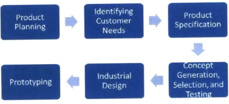
Product development methodology was adopted for robot prototyping [11] and it turned out that it works well in designing biologically-inspired robots for stage performance. The general product design work flow is presented in Figure 2.1.
Prior to the product development process is the product planning phase, in which a designer identifies the opportunities, allocates the resources and sets up the milestones, completes the pre-project planning, and defines the project mission. The second step is about identifying customer needs. In this phase, I interviewed the creative team of the opera, prioritized the robot requirements in a hierarchical structure, allocated a weighting on each requirement, and reflected on the process and its outputs.
Product Spe cification "oncept Generation, Selectionl, and L Testingi
Figure 2.1 Product design workflow
The third phase has two outputs: they are the design target and final specification. The design target is defined by the hierarchy and evaluation benchmarks on customer needs, while the final specification is a refined specification based on the selected concept,
feasibility testing, technical modeling, and trade-offs.
Subsequently, several design concepts were generated through the external (e.g., literature review, patent search) and internal searches (individual discussion, brain storming sessions). The best concept was selected based on an evaluation matrix, which has criteria, reference concepts, and weightings. Industrial design methods, such as sketch modeling and storyboarding [12], were used to communicate with the opera's creative team.
Design methods during the prototyping phase will be discussed in sections 2.4 and 2.5, respectively. Other concerns such as human factors, visual, tactile, safety and convenience criteria will be discussed in section 2.6. The detail implementation of above-mentioned methods will be presented in Chapters 3 and 4.
2.4 Mechanical System
The acquisition of useful engineering knowledge from studying living creatures is not easy. Their shapes and locomotion patterns are determined by a large number of factors. To extract the contributions of desired factors from their large-scale systems requires not
Product Planning Prototyping Identifying Custorner Industrial Design
only careful observations but also many experiments in both mechanical and electrical systems. It should be mentioned that a direct engineering application based on a biological approach is often difficult due to the constitutive elements of a biological system, such as muscular and neural systems, that are very different from ideal engineering elements, which can be utilized by man. This difference needs to be kept in mind throughout the low-level design phase.
After the selected concepts are approved, three essential tasks (analytical modeling, numerical simulation, and engineering drawings) will be performed in the mechanical design phase. Analytical modeling serves as a solid foundation for understanding and verifying the driven mechanism and locomotion patterns of the robots. For example, the
joint geometry and kinematics, energetic aspects of locomotion, and analytic representation of muscle line of action.
However, solely using analytic model may not be adequate because of the complexity and dynamics in any robot system. As a result, structural and kinematic analyses with disturbance factors are usually performed in numerical simulation software. In this work,
MSC Adams was used to test the kinematic model; SolidWorks was used to test the
assembly interference; ANSYS were used to perform FEM analyses on critical robot components. Engineering drawings can be done using either of these techniques: classic drafting tools, two-dimensional (2D) (e.g., AutoCAD) or three-dimensional (3D) computer software (e.g., SolidWorks, Siemens NX mechanical design tools).
Among the physical hardware, actuators use a variety of approaches including pneumatic, hydraulic, electrical actuators, electromagnetic motors, and artificial muscles. Their driven mechanism also differs from each other, ranging from direct drive, to gear/chain/belt drive, to cable drive, etc. In their seminal paper of biologically-inspired actuators, Hunter
et al. compared different types of actuator technologies for robots [13]. This paper serves a source of guidance in choosing actuators based on their characteristics, mechanical properties, and application requirements. Due to the rapid progress on manufacturing
technologies, novel actuators have become more affordable to research applications. In this thesis project, low-cost electrical linear actuators were used in the Sofa robot.
2.5 Electrical System
The electrical system-the sensors, communication modules, control unit, and power supplies-enables robots onstage to perform as characters and interact with human actors. Pratt reviewed physical hardware suitable for biologically-inspired robots [9]. Even since then, plenty of new components and novel methods have become available with the advent of emerging technologies. Here, the thesis does not intend to summarize all of them but to discuss two components that have been widely used recently.
In our work, we used MEMS-based accelerometers to measure the tilt angles of robot segments. Rigid body motion in the 3D space can be described using 6-DOF information (three translational and three rotational DOFs). A common solution is to use precision potentiometers or optical encoders for measuring rotational angles. Some benefits of these methods are high accuracy and fast response. However, due to the installation of mechanical attachments, the robot becomes larger and heavier. In addition, these methods are sensitive to surrounding distortions, such as supply voltage drift, light and temperature changes, etc. Here I chose MEMS-based accelerometers because they are standalone and capable to take accurate measurements when robot parts are stationary or moving slowly. The technical details about the implementation will be presented in Chapter 4.
Another new technology used in this work is the ZigBee wireless network. ZigBee is a specification for a suite of high level communication protocols using small, low-power digital radios based on the IEEE 802.15.4-2003 standard for wireless personal area networks (WPANs). The protocol defined by the ZigBee specification is intended to be simpler and less expensive than other WPANs, such as Bluetooth. Its data rate is relatively low compared to Bluetooth but enough for sending and receiving control signals to the furniture robot. It was chosen for the project because of its low cost, long
battery life, and secure networking. The technical details about the implementation will be presented in Chapter 4 as well.
Other factors that should be taken into consideration are Radio frequency (RF)/Electro-Magnetic Radiation (EMR) constraints, thermal constraints, and battery life constraints. Considering the possible presence of other wireless devices in the performance venue, I use the 2.4 GHz ZigBee network; electrical devices are also deactivated when not working; heat sinks are added onto motor drivers and LED lighting boards.
2.6 Other Concerns
There are some other concerns in the theatrical context:
1. Simple vs. Complex: general design principle states that simplicity should be a key goal and unnecessary complexity should be avoided. This can bring a lot of benefits (e.g., easy to manufacture and to maintain). On the other hand, the robots need a certain level of complexity to impress the audience, to perform their tasks and to coordinate with narrative and musical materials in the opera. It is a time consuming but necessary process for a designer to strike a balance between ease of manufacture and level of complexity. The tradeoffs that are made will be presented in the lessons-learned section in Chapters 3 and 4.
2. Large vs. Small: onstage robots differ from home entertainment robots or industrial robots, not only because of the differences in their applications but also their sizes. They cannot be too small since the audience need to watch them over distance. On the other hand, the increase in size usually results in increased weight and may also decrease their structure stiffness. It is the designer's responsibility to find the tradeoff.
3. Noise level: every opera is a unique audio and visual experience. It is very important to control the noise at a reasonable level. This can be done with a careful design in
the mechanical system. For example, changing the robot driving mechanism from gear to belt or cable can dramatically reduce the noise. If a designer cannot find any affordable way to do that, he may want to use the sound as a drama or theatre element.
4. Materials: when choosing the construction material, we have to consider the role of the robot character. In our design, these robots are furniture in the room, so they need to stay consistent with the decoration style of the house. The lighting on stage may also affect the appearance of the robots. It is good to have a material library on hand and to do some field research at the theater.
5. Safety: an emergency stop is a must on both software and hardware sides of the
robots. There is no exception to Asimov's three laws of robotics.
2.7 Summary
In this Chapter, I reviewed the concept and examples of biologically-inspired robots, and discussed how the processes of product development can be applied into the design and implementation of robots. I also discussed design methods and hardware components which can be used in mechanical and electrical systems. Theatrical factors were discussed in section 2.6 and will be continually discussed throughout the thesis. Detailed information will be presented in Chapters 3 and 4.
CHAPTER 3
A WALKING ROBOT
-
MEI-MEI
3.1 Introduction
Stage performances present many challenges and opportunities in the field of robotics. This thesis project aims at a family of furniture robots that look and act like organic entities for the production of Tod Machover's new opera, Death and the Powers. The first robot, called Mei-Mei, is a six-legged walking robot that was developed in the lab as a moving workbench. Its design was inspired by a Theo Jansen mechanism in which a rotational movement is converted to a walking motion through bar linkages. With six legs driven by two separate motors, it can move forward, backward, and turn around with differential steering control. The robot is fully teleoperated using a RF remote controller and RoboteQ's AX 1500 motor controller.
3.2 Mechanical System
The proposal for building the Mei-Mei robot was an accident. It was in a group meeting in May 2009 when Tod first talked about his idea of having moving furniture in the opera. At that time, I almost finished the mechanical design of the chandelier, another robot element onstage and tried to contribute to the opera with something new. So, I jumped into the work and wanted to have a fruitful summer ahead.
When working on this robot, I did not realize that the product development methods can be applied to the design of stage robots. So, I started with a literature review in
architecture, zoology, visual art, and robotics. My inspirations came from two remarkable works: Leonardo Da Vinci's mechanical lion and Theo Jansen's beach animals (see Fig. 3.1). In 1515 Leonardo built his famous self-propelled lion that reportedly walked from its place in the room and opened its breast full of lilies, presenting them as a token of friendship from the Medici to Francis I, King of France. More recently, Theo Jansen, a
Dutch artist and kinetic sculptor, built large works that resemble skeletons of animals and are able to walk using the wind on the beaches of the Netherlands. The movement of these robots looks elegant and has a quality of living creatures. So, I decided to build my robot based on their works.
Figure 3.1 Leonardo Da Vinci's mechanical lion (left) and Theo Jansen's beach animals (right) (adopted from [14, 15])
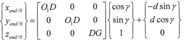
When it comes to mechanical structure, both robots share a common element: the four-bar linkage. Since it will also be used in the Mei-Mei robot, I did the analytic modeling on the structure using forward kinematics and drew the trajectory envelope of its end effector. In forward kinematics, the three rotational angles (y, a,
p)
are known and used to define the position of end effectors (Xend/l1 e Zend/1). In Fig. 3, L and L2 are the length of the upper and lower arms. The equation for the end effector can be obtained by applying trigonometric properties to four-bar linkage. In the plane of the four-bar linkage, there is,Xendi
O
D
Yendl= 0 Zendl1L
0 0 01D 00
cosry
0sin
y
DG_ 1 (3.1)This relation is transferred from its local coordinate into the global coordinate system and we have,
Xendio
/1D
Yendo 0 ZendI0 L 0 0 OD 0Using Eq. (3.2), the trajectory envelope graph helps to calculate the length of cross. (a)
0
cos y
-d sin y
0 siny + d cos yDGj
1 f
0
of its each (3.2)end effector was drawn as Fig. 3.2 (d). This step and the height that the structure can
(b) d 01 YeA&I '000 Y, J 00 J YO (d) (c)
Figure 3.2 Kinematic analysis of four-bar linkage
(a. four-bar linkage in 3D space; b. four-bar linkage in its local coordinate plane; c. the relation between local and global coordinate system, top view; d. trajectory envelope of end effector)
Based on four-bar linkage, Theo Jansen mechanism has 8 linkages per leg and 1200 of crank rotation per stride. This mechanism has bar linkages arranged such that a rotation movement is converted to walking pattern of a four legged animal. Step height is
primarily achieved by a parallel linkage in the leg that is folded during the cycle angling the lower portion of the leg. The best combination of leg length can be figured out through analytic methods and verified by numerical simulations. A flash animation of Theo Jansen mechanism is available online, in which you can move sliders to change the lengths of corresponding bars [16]. 3D modeling of these linkages were built in SolidWorks and virtually assembled for testing.
V,
Figure 3.3 Robot driven system (belt driven, left; gear box, right)
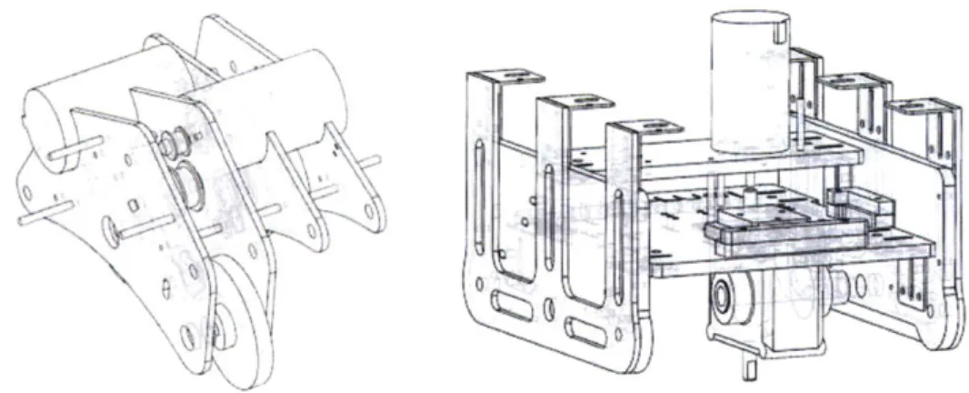
Figure 3.4 Mei-Mei robot (left) and its legs (right)
The first drive mechanism tried was the belt-driven mechanism. The trial run was quite promising since the overall installation was small in size and very quiet when running. However, it requires a mechanical check periodically to make sure the belts are engaged well with the gear wheels. Even so, its belts slipped very often partly because the robot is
heavy, partly because of the absence of a belt tensioner system. So, I chose to use the A-2B-8-HO500G gearbox with 50:1 gear ratio from SDP/SP to drive the robot (see Fig. 3.3). Figure 3.4 (a) shows the appearance of the Mei-Mei robot and Figure 3.4 (b) is a close look of its bar linkage system. Detailed engineering drawings are archived at the project website at http://web.media.mit.edu/-saga/projects/birf.htm.
3.3 Electrical System
Its six legs were divided into two groups mechanically and driven by two separate motors connected to their cranks. Thus, I chose the RoboteQ's AX 1500 dual channel motor controller in this application. The controller is designed to convert commands received from a radio control (R/C) receiver, analog joystick, wireless modem, or RS232 serial port into high current output for driving one or two Direct Current (DC) motors. Its two channels can either be operated independently or mixed to set the direction and rotation of a robot by coordinating the motion on each side.
Proportional Gain X Desired Position E ro - j X output Analog Position /
Sensor Measured Position Integral
Gain or
Optical Encoder
Differential Gain
Figure 3.5 PID algorithm used in position control
In the Mei-Mei robot, I used the R/C mode with open-loop control. In this mode, the speed or position information is contained in pulses whose width varies proportionally
with the joystick's positions. There is no feedback control loop in the robot controller. The electrical power wiring and R/C cable wiring diagrams of the AX 1500 controller
can be found in its user's manual [17].
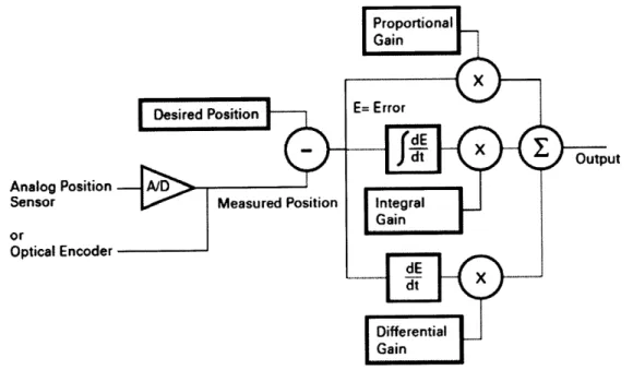
For better control and improved safety, the controller can be configured with quadrature optical encoders to continuously monitor the errors and to perform correction with closed loop speed or position control. Figure 3.5 shows a representation of the Proportional, Integral and Differential (PID) algorithm. Every few milliseconds, the controller measures the actual motor speed and subtracts it from the desired position to computer the speed error. The resulting error value is then multiplied by a user selectable proportional gain. The resulting value becomes one of the components used to command the motor. The effect of this part of the algorithm is to apply power to the motor that is proportional with the difference between the current and desired speed: when far apart, high power is applied, with the power being gradually reduced as the motor moves to the desired speed. The differential control component of the algorithm computes the changes to the error from one period to the next. The differential component will also greatly help dampen any overshoot and oscillation. The integral control component of the algorithm performs a sum of the error over time. This component helps the controller reach and maintain the exact desired speed when the error is reaching zero (i.e. measured speed is near to, or at the desired value). These gain values can be selected with Madab Simulink simulations.
3.4 Lessons Learned
There are four lessons that I learned from my experience:
1. Weight: the total weight of the robot needs to be defined carefully in the design specification if it is going to the stage. When designing the Mei-Mei robot, I did the analysis to make sure that the motors and gear boxes selected can provide enough torque to drive the robot. These analyses also ensured the robot structure has enough
stiffness so that it won't deform a lot or crash when moving. Later, the trial run endorsed these analysis results. However, it turned out the robot is too heavy and requires two or four people to lift it onto the stage. This is not convenient at all.
2. Dimension: similar to the weight factor, the volume size of the robot is another big concern. Stage robots often need to be shipped from one location to another in a container. The ease of packing and volume optimization are very critical. When
designing such a robot, it is better to take this into consideration at the beginning. Modular and foldable designs are preferred.
3. Maintenance: when giving touring performances in different parts of the world, we
definitely want to make everything as reliable as possible. No director wants to ship tons of spare parts or an entire machine shop overseas. Unfortunately, the Mei-Mei robot has more than 1000 components and requires almost equivalent maintenance time after each performance. These include checking the bearings, adding grease, recharging the battery, and tightening the screws on the robot.
4. Machining: the components of the Mei-Mei robot have a lot of curves and round corners which make mounting and holding them on a drill or a mill cumbersome. Aesthetic factors should also cooperate with engineering and fabrication concerns.
Here I share the important lessons that I learned from more than six-month design and fabrication work on the Mei-Mei robot. After that, I began to reflect on my experience: what is the difference between stage robots and other kinds of robots? How do these differences affect the design of the robot? What kind of methods can we introduce to help the design? I remembered that I was facing the same problems when designing something in my production development class. This inspired me to try product design methods in this thesis project. Later, they were proven feasible and effective in making
3.5 Summary
The Mei-Mei robot was the first furniture robot that I designed for the opera. Its design was inspired by Theo Jansen mechanism and the robot itself is driven by two DC motors with differential steering control. In this chapter, I presented the analytic model of four-bar linkage-the basic element of its leg and discussed the PID control algorithm that can be implemented on the robot for better performance.
The robot itself was successful in that it has the appearance of an organic entity and has elegant movement. However, it also has some disadvantages that prevent it from becoming a prefered model for stage-performance robots. I reflected the design process and decided to adopt product design methods for my next robot.
CHAPTER 4
A TRANSFORMABLE ROBOT
-
SOFA
4.1 Introduction
In October 2009, Alex McDowell, Bob Hsiung (development manager), and I had another meeting about the set pieces. Alex reviewed the Mei-Mei robot and presented his idea about some other furniture robots onstage. There. are two important comments on the Mei-Mei robot: (1) it does not seem to originate from the same robot family as other robots on stage. In the story, all robots were created by Nicholas, Simon's adopted son. While the OperaBots, nine assistant robots in the opera, have an early-prototype-like look and use a lot of plastics components, the Mei-Mei robot was totally made of aluminum. (2) Since the Mei-Mei robot has legs and motors, a clue on its functionality is given to the audience at a glance. It will be hard to impress them with its movement later
on.
We also discussed what we want from the robots. These robots should have the appearance of organic entities, look like something from the near future, move in a funny way (e.g., lurching, gliding, etc.), and can be used as furniture on the stage. But we had no idea what they would be at that time.
4.2 Mechanical System
Since nature has discovered many clever solutions to challenging problems, the biological world has proven to be an endless source of inspiration and guidance for the development of future robots. In this project, I chose the approach of making biologically-inspired robots for stage performance.
The work strictly followed the standard product design process discussed in section 2.3. Firstly, we defined and identified the customer needs, in this case, the robot design requirements in terms of its visual appearance, the functionality, the movement. It is
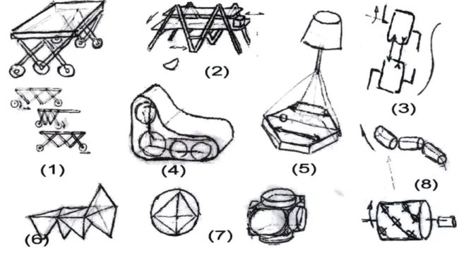
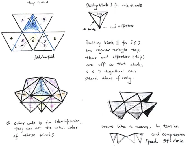
important and necessary to get the opera creative team involved into the discussion and decision making process. When this information is clarified, I started brainstorming sessions and came out with several design concepts as shown in Fig. 4.1. Design candidates No. 1, 5, and 6 were inspired by worms; No. 2 may jump like a grasshopper. No. 4 may change its form and move like bacteria. No. 3 and 8 will mimic the behaviors of a lizard and a snake, respectively. The tumbleweed offered the inspiration for No. 7.
4L
(2)
(1)= (7)(5)
(8)
Figure 4.1 Design candidates of biologically-inspired robots
However, it may still be hard to describe the appearance and behavior of the robots using a sketch drawing only. So I sent a detailed drawing of the design candidate No. 6 (see Fig. 4.2) to an animator so that he can visualize this design. His flash animation can be found on project website at http://web.media.mit.edu/-saga/projects/birf.htm. Visualization helped me a lot in communicating with other people in the production team and refining the design concept.
The Sofa concept was selected among these candidates. In order to determine the size and functionality of the robot, we build a graphic model (see Figure 4.3), and two
-v3( A ck 1 -1, 1-5.4. a-AS b a ae A II toY (- C, e. off s Gr 5 6. ~7 -4,,ek cO a an 6.j I C"Wr "."A is AL A.,A
mWQd
7
5fft / nFigure 4.2 Details of design candidate No. 6 (Sofa)
Figure 4.3 Computer graphic model of the Sofa (by Peter Torpey) ... ... .. ...
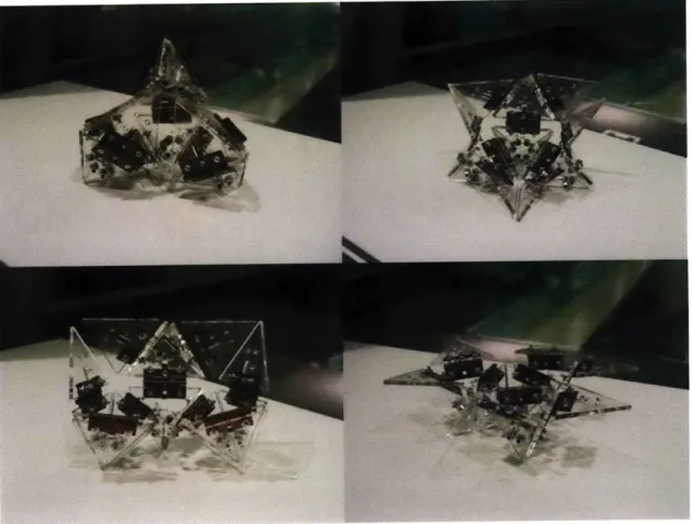
scale cardboard models, and a 1:12 scale model based on the design concept. After building the full-size cardboard models, I decided that the top plane of the Sofa would be around 24 inches above the ground level. The scale model was used for choreographic designs and shooting a stop-motion movie of the robot. The video can be found on project website as well.
Figure 4.4 Scale model of the Sofa robot
After the concept was approved by the creative team, I started with mechanical design. Through the lessons learned from the Mei-Mei robot, I want to make the design as simple as possible. Instead of using a DC motor to direct drive a rotational shaft for the tension and extension of a joint, here I chose a linear actuator to open and close the joint between two modules. The design has fewer parts for fabrication and installation, therefore, gives the robot a neat appearance, and also makes the maintenance easier. On the other hand, the mechanical design will be tricky and the control will be a more complicated.
In order to prove that the structure can move in the designed way, I built and tested a simplified model in MSC Adams. The direction of its movement can be controlled with the phase difference between the control signals given to three linear actuators. The
details about the control algorithm will be discussed in the electrical system section.
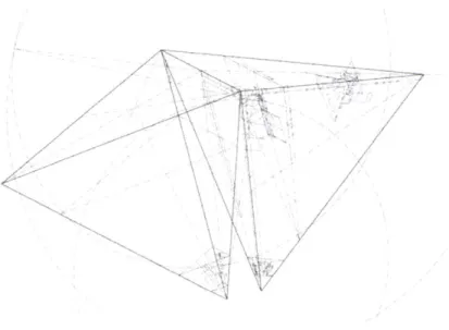
There are many variables in the mechanical structure, such as the position of the linear actuator mounting plate, the opening angles between two modules, and the stroke length of the linear actuators. One change in a factor often affects many others. So, I drew a sketch model in SolidWorks and defined the geometric relationships between some elements with formulae embedded inside (see Fig, 4.5). This allowed me to experiment with different configurations and to optimize the structure before started designing individual components.
Figure 4.5 Geometry sketch drawing of the Sofa robot
Another engineering problem is about the stiffness of the structure. It is difficult to achieve a rigid structure about a half-sofa size with %/ inch thick Polypropylene plates. Although it is possible to build a stiff structure with aluminum, it is not feasible because of the theatrical considerations that I mentioned previously: first, this solution makes the robot too heavy, and may result in high noise level when moves; second, there is a requirement from the opera creative team that the robot should be translucent and has
the similarity with the OperaBots in materials. So, I compared the material properties and mechanical characteristic of Polyethylene, Polycarbonate, and Acrylic and decided to use Polyethylene for the construction of the robot.
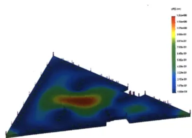
The structure stiffness was achieved using following methods: first, I use the pyramid structure for all modules of the robot. The structure is capable of supporting a large load without twisting itself or having significant deformation; second, every plate is connected to its neighbors with joint pieces so that they construct a closed form together and any load applied can be passed along the structure; third, a middle plate was added inside of each module for extra support, and for mounting equipments. I also analyzed the structure with FEM software. Figure 4.6 shows that the top plate deformation of the side modules under an extremely large load.
I
Figure 4.6 ANSYS analysis of top plate (under 500 lbf, maximum deformation 1.29 mm)
The fabrication was done at the machine shops in the MIT Media Lab and Edgerton Center. The facilities that were used in the process include water-jet, laser cutter, Computer Numerical Control (CNC) machines, etc. SolidWorks models and engineering drawings are archived on the project website. Figure 4.6 shows the rendering model done by Computer-aided Design (CAD) tools and the finishing look of the Sofa robot.
Figure 4.7 Rendering model and full-scale prototype of the Sofa robot
4.3 Electrical System
The electrical -system has three tasks: driving the actuator, sensing the orientation of the modules, and controlling the lighting. The first two will be discussed in this section and the design of the lighting system will be presented in section 5.2.
The Sofa robot was designed with translational and rotational motion. It has a similar structure to the star robot that is presented in [18], thus the same sinusoidal input may be used, probably with several experimental adjustments. Its modules form a star of three points with an angular distance of 1200, which enables it to move on a 2D surface, in three directions, as well as performing rotations in the yaw axis.. The locomotion is
achieved by means of sinusoidal waves. If two adjacent modules are in phase and the opposite has A# e [100,150], it moves on a straight line in the direction of the module out of phase. However, this movement is very surface-dependant. When the increment of phase between the three modules is 1200, for example, 1 =0" ,
#2
=120" and$3
= 2400, the robot performs a slow rotation in the yaw axis. The sinusoidal input to move a modular robot with a star configuration is:V = A sin [gt+(i-1)A# (4.1)
T
where A is the amplitude of the wave. i is the actuator number (from 1 to 3 in the direction of travel). T is a factor selected with several experimental adjustments. A# equals to 1200 as the phase difference between actuators.
The resultant waveform is shown in figure 4.8:
30 V2 20 5 V1 V4o V3 -30 0 S o I o 25 30 35 40 Tkne
Figure 4.8 Driving waves for rotational motion
With reference to the equation above, the following firmware code was written to control the three linear actuators on the Sofa.
void rotateFun()
float comfactor, throttle_1, throttle_2, throttle_3;
comfactor = 2*PI*i/PERIOD;
throttle_1 = mapFloat(sin(comfactor+PHASE_1), SINUAMPLOW, SINUAMPHIGH, SERVOLOW, SERVOHIGH);
throttle_2 = mapFloat(sin(comfactor+PHASE_2), SINUAMPLOW, SINUAMPHIGH, SERVOLOW, SERVOHIGH);
throttle_3 = mapFloat(sin(com_factor+PHASE_3), SINUAMPLOW, SINUAMPHIGH, SERVOLOW, SERVOHIGH);
if (throttle_1>0) {throttle_1 = throttle 1*COMPZFACTOR;} if (throttle_2>0) {throttle_2 = throttle_2*COMPZFACTOR;} if (throttle_3>0) {throttle_3 = throttle_3*COMPZFACTOR;}
mcontroller l.write(throttle_1);
m controller 2.write(throttle 2); mcontroller_3.write(throttle_3);
delay (DELAY);
}
The firmware of the Sofa controller can be found in Appendix A.
The control signal is sent to three SyRen 25 motor drivers from Dimension Engineering. These drivers are set in their R/C mode, which enables the driver to interface with the microcontroller using standard R/C pluses. The speed and direction of the motors can be set using a pulse. For example, a 1500 us pulse is full reverse and a 2000 us pulse is
full forward. The wiring diagram and more details can be found in the user's manual of the driver [19].
The other task of the electrical system is to measure the orientation of the robot module in real time and to use the information to adjust the robot accordingly. Here a MEMS-based capacitive accelerometer from STMicroelectronics (LIS3LV02DQ) is used for measuring the tilt angles. The sensor was chosen because of its small package size, low weight, and high accuracy. This sensor measures 7 mm X 7 mm X 1.8 mm, weighs about
0.2 gram, and has an effective sensing range of ±2g/±6g. It includes a sensing element capable of measuring linear acceleration signals over a bandwidth of 640 Hz and an IC interface able to send out the data in 12/16 bit data representation through an Inter-Integrated Circuit/Serial Peripheral Interface (12C/SPI) serial interface.
0.8 0 A 0.6 S0.4 0.2 0 0 20 40 60 80 100
True Tilt Angle (degree)
Figure 4.9 Measurement errors of the accelerometer (average: 0.380)
The accelerometer in its steady state can be directly used to measure the gravity vector g which is always vertical to the horizontal plane. Here we define that the sensor reaches its steady-state conditions in the state of rest or uniform motion characterized with 1g acceleration caused by gravity. Tilt angles are then calculated from three orthogonal acceleration components as:
a= + a + a ~ g; (4.2)
G=sin_'- -; $= sin- -oo a 43
where is [ax a, az IT is the gravity vector measured in the local frame of the sensor. 0 and
#
are pitch and roll angles in the global frame.An experiment on the LIS3LV02DQ accelerometer with 12/16 bit data representation (11-bit ADC) shows that it has the average error about 0.38' (see Fig. 4.9). The sensor is accurate enough for measuring title angles of a robot module when it is stationary or moves slowly. The sensory data can be used to perform a close-loop feedback control for initializing and positioning robot modules. Detailed information on sensor calibration
and error cancelling can be found in [20]. The firmware program for reading sensor outputs through an 12C/SPI serial interface can be found in Appendix B.
In addition, the wireless communication between the robot controller and a host computer is achieved through a Zigbee network. The components for constructing the network include a pair of Xbee 2.4GHz chip antenna from Digi, an Arduino Funnel I/O
(Fio) board, and an Xbee Explorer USB board.
The computer sends control signals and receives sensory data through a virtual serial port, which is physically connected to an Xbee Explorer USB board. The Xbee antenna module on the Explorer board takes the 802.15.4 stack (the basis for Zigbee) and wraps it into a simple to use serial command set. Then the data is transmitted through a point-to-point network to another antenna module mounted on an Arduino Fio board, and finally, the Fio board interfaces to sensors and motor drivers according to the command that it receives.
Configuring Xbee module into different modes, such as point-to-point and multi-point networks, is supported by the X-CTU software from Digi. The tutorial can be found in the user manual of the software [21]. The Fio board is wirelessly reprogrammable. The tutorial on wireless bootloading can be found online [22].
4.4 Lessons Learned
The Sofa is a modular robot that can transform itself into a sofa onstage and walk with a rolling, lurching, and gliding moving. It also has the features that can be endowed with interactive behavior structured around scenes, beats, and actions. Thus, the design of this robot was successful.
1. Mobility: since the robot has an irregular shape and smooth surfaces, it is not easy to
move it on the stage or lift it up on a pickup truck. If handles were put on the robot, it will make this work much easier.
2. Maintenance: when users want to recharge the battery in the Sofa, they need to open the top plate in the central module. This operation takes about 20 minutes. It will be better if the battery module is removable from the robot and can be replaced within a few minutes. In addition, a transparent quick-release inspection window may also be added into the design. This will make the maintenance work faster and easier than the current design.
The other concern was about planning. Since the requirements and the focus of interest may vary along the robot development, it is important to communicate well with people in the creative team and to review the priority list of the robot elements periodically.
4.5 Summary
There are many challenges in designing robots for the stage. The design of these robots should not only incorporate technological, conceptual, and aesthetic innovations, but also coordinate with narrative and musical materials in the performance.
Theo Jansen said, "The walls between art and engineering exist only in our minds." The work shown in this chapter gives an example of achieving artistic goals via a series of engineering approaches. This chapter also discussed some lessons that I learned from the design and implementation of the Sofa robot.
CHAPTER
5
IMPLEMENTATION OF STAGE ELEMENTS
5.1 Introduction
While the robotics community strives to define functional models and theories grounded in the physical reality of the robotic agent, art, and in particular theatre, are more concerned about staging the unreal. Much research has been done on the theoretical level: theatre theorist Horakova entitled a paper: "Robots between Fictions and Facts" [23] and the seminal book from Reichardt is entitled: "Robots: Fact, Fiction and Prediction" [24]. Demers related the inter-related constituents of a robot actor to human perception in the following areas: the historical lineage of the uncanny valley, artificial intelligence (AI), anthropomorphism, causality and animacy [25].
This chapter mainly focuses on some engineering aspects of stage robots on a practical level. Our experimental work and some related work on robot lighting, visual and sound effects will be presented in the flowing sections. However, the implementation of stage elements is a quite broad topic and this chapter only covers some specific problems and their solutions that were experienced during the development of our stage robots.
5.2 Lighting
Modern stage lighting is a flexible tool in the production of theatre, dance, opera, and other performance arts. The functions of lighting include illumination, revelation of form, focus, setting the tone of a scene, establishing or altering position in time and space, projecting scenery, triggering the action onstage, and composition. The four main qualities or properties of lighting are intensity, color, pattern and focus [26, 27].
This work designed and implemented a local lighting system to illuminate the Sofa robot from inside (see Fig. 5.1). The system has individual lighting control over each robot
module and the features include wireless dimming, fade-in/-out, and strobe/flashing.
Figure 5.1 Sofa robot with its internal lighting
The circuit diagram of the lighting board is attached in Appendix C. The lighting control board includes an ATmega168 microprocessor, a 3021 BuckPuck LED driver from LuxDrive, and supporting circuits. The control input pin of the LED driver is fed with Pulse-width Modulation (PWM) signal from the microprocessor. The LED driver is set as its external control mode, also known as its adjustable current configuration. In this mode, the driver delivers an adjustable output voltage according to the input control voltage. The wiring diagram of the LED driver can be found in its data sheet [28].
PWM is used to regulate the input voltage of the LED driver in this application. It uses a rectangular pulse wave whose pulse width is modulated resulting in the variation of the average value of the waveform. By switching voltage to the load with the appropriate duty cycle, the output will approximate a voltage at the desired level.
Each lighting circuit has 6 PWM outputs and has a bidirectional 2-wire 12C bus which allows us to chain 255 boards together. Thus, the circuit can control up to 1530 independent lighting channels theoretically.
In 1994, Milgram and Kishino defined a Mixed Reality (MR) as "... anywhere between the extrema of the virtuality continuum." [29] It is possible to introduce MR technology into theaters to produce new environments and visualizations where physical and digital
objects co-exist and interact in real time.
This work did some preliminary research on implementing a MR system with Infrared (IR) tracking and high resolution projection. This investigation is based on the Physical
Computing Robot Tracking Installation project by Chris Rojas (see Fig. 5.2). I did some
experiments accordingly, but didn't get a chance to integrate the system into the Sofa installation due to the limited time that I have.
Figure 5.2 Visual Effects of the Physical Computing Robot Tracking Installation (adopted from [30]) .
Rojas's project used a PlayStation 3 (PS3) Eye camera, an Optoma EX525ST DLP short throw projector the ceiling, Community Core Vision (CCV) and Processing running MSAFluid [30].
Its positioning system had an IR LED pointing upward towards a modified PS3 camera which only sees infrared signals. The hardware modification was done by removing the IR blocking filter and adding a visible light blocking filter in the camera. The vision data was collected by a driver developed under CL-Eye Platform Software Developers Kit (SDK), which can be downloaded from http://codelaboratories.com/downloads. The computer vision program was developed under CCV, which is an open
platform solution for computer vision and machine sensing. It takes a video input stream and outputs tracking data (e.g. coordinates and blob size). More information about CCV can be found at http://ccv.nuigroup.com. Last, a rendering engine was developed under MSAFuild, a library for solving real-time fluid dynamics simulations based on Navier-Stokes equations and Stam's fluid dynamics solver [31]. A ceiling-mounted projector gets the rendering stream and projects it around the robot.
The same solution can be used for the Sofa robot. Considering the disturbance from other lighting sources on the stage, a possible improvement on this project is to add a tagged source on a robot to indicate its location. One of the most robust ways of sensing a particular object is to interrogate the environment with a source at a specific frequency. Since the camera used here has a sampling rate of 100 frame per second, it is capable of capturing the image of a LED blinking at 50 Hz or at lower frequency. This allows us to look for a response at that single frequency and ignore the rest of the noise in the
environment.
5.4 Sound Effects
Throughout the development of these furniture robots, I tried to design some acoustic instruments that can be attached and used on these robots. I made a tunable Kalimba
(see Fig. 5.3) as a part of the experience. This instrument consists of a wooden sound box with 5 keys (strips made by spring steel) attached to the soundboard. It also has a wheel that can be tuned to adjust the length of the key. The vibration in the keys is sensed by a guitar pickup mounted on the soundboard and then the signal runs to an amplifier, which drives a speaker.
The sound of this instrument has a similar quality of a bass guitar and it produces funny
and interesting sound effects by tuning a key when playing a note. A thought was to attach the wheel with a turning part on the robot and associate the sound effect with the motion of the robot, but it turned out to be a difficult task since it is hard to find a
mounting point on the robot without changing its appearance and to mimic the variable and dynamic sound quality produced from the instrument by a human player. In the end, we decided to let the Sofa robot keep its silent motion and for the OperaBots, wireless speakers are attached on them. It might be a good idea to design an instrument ahead, start over from that, and then incorporate its features and parts on the robot.
Figure 5.3 Prototype of a tunable Kalimba
5.5 Summary
This chapter discussed some engineering aspects (e.g. lighting, visual and sound effects) of the design and implementation of stage elements for stage robots. New advances in technology such as vision-based motion capture, low-cost projectors, film-like carbon nanotube speakers, and high-brightness LED lightings, are making opera robots come true on stages. Many products based on these technologies are commercially available in the market. All these present many challenges and opportunities for designers to create an amazing visual and audio experience for their audience.
CHAPTER 6
CONCLUSION AND FUTURE WORK
This thesis aimed to further the state of the art in stage robot design. As part of this work, we considered robot design as a discipline in its own right, taking inspiration from product design, mechanical engineering, human interface, choreographic design, and sensitivity to music. The result of this work was two performance-ready robots. I collected feedback from the designers, artists, and engineers of Death and the Powers to further refine these robots. My work was judged according to four criteria proposed by Hoffman: the visual appearance, the overall functionality, the quality of movement, and the fluency of HRI [11].
Here I created a family of furniture robots that look and act like organic entities for the production of Death and the Powers. Mei-Mei is a six-legged walking robot that is being developed in the lab as a moving workbench. It can move forward, backward, and even turn around with differential steering control. Sofa is a modular robot that can transform itself into a sofa onstage and walk with a rolling, lurching, and gliding motion. These two robots were also designed in the way that they will be endowed with interactive behavior structured around scenes, beats, and actions. The design of these robots not only incorporates technological, conceptual, and aesthetic innovations, but also coordinates with narrative and musical materials in the opera.
These robots were demonstrated during two Media Lab sponsor weeks in October 2009 and May 2010. The Sofa robot was also brought into the opera rehearsal in June and July 2010. They both got a lot of public attention because of their novel design, imposing appearance, and elegant movement. Karole Armitage, the choreographer of the opera, is also considering bringing the Sofa into the dance performance that she is working on.
The design of these robots was successful. Possible future work includes integrating autonomous interactive features into these robots. In the long term, we will design and
![Figure 3.1 Leonardo Da Vinci's mechanical lion (left) and Theo Jansen's beach animals (right) (adopted from [14, 15])](https://thumb-eu.123doks.com/thumbv2/123doknet/14164462.473635/18.918.193.728.274.484/figure-leonardo-vinci-mechanical-theo-jansen-animals-adopted.webp)