https://doi.org/10.4224/20378393
READ THESE TERMS AND CONDITIONS CAREFULLY BEFORE USING THIS WEBSITE.
https://nrc-publications.canada.ca/eng/copyright
Vous avez des questions? Nous pouvons vous aider. Pour communiquer directement avec un auteur, consultez la
première page de la revue dans laquelle son article a été publié afin de trouver ses coordonnées. Si vous n’arrivez pas à les repérer, communiquez avec nous à PublicationsArchive-ArchivesPublications@nrc-cnrc.gc.ca.
Questions? Contact the NRC Publications Archive team at
PublicationsArchive-ArchivesPublications@nrc-cnrc.gc.ca. If you wish to email the authors directly, please see the first page of the publication for their contact information.
NRC Publications Archive
Archives des publications du CNRC
For the publisher’s version, please access the DOI link below./ Pour consulter la version de l’éditeur, utilisez le lien DOI ci-dessous.
Access and use of this website and the material on it are subject to the Terms and Conditions set forth at
Guide for the installation of photoluminescent exit stairway markings in
buildings
Proulx, G.; Bénichou, N.; Kyle, B. R.; Foo, S.
https://publications-cnrc.canada.ca/fra/droits
L’accès à ce site Web et l’utilisation de son contenu sont assujettis aux conditions présentées dans le site LISEZ CES CONDITIONS ATTENTIVEMENT AVANT D’UTILISER CE SITE WEB.
NRC Publications Record / Notice d'Archives des publications de CNRC:
https://nrc-publications.canada.ca/eng/view/object/?id=26627a24-f2f8-4d52-a174-3ae4e0742a36 https://publications-cnrc.canada.ca/fra/voir/objet/?id=26627a24-f2f8-4d52-a174-3ae4e0742a36
National Research Council Canada and
Public Works and Government Services Canada
Guide for the Installation of
Photoluminescent Exit Stairway
Markings in Buildings
National Research Council Canada
and Public Works
and Government Services Canada
Guide for the Installation of
Photoluminescent Exit Stairway
Markings in Buildings
Liability Disclaimer:
Except as expressly stated herein, the National Research Council Canada and Public Works Government Service Canada disclaim any warranties, expressed, implied, or statutory, of any kind or nature with respect to this publication, including without limitation any warranty of merchantability or fitness for a particular purpose. The National Research Council Canada and Public Works Government Service Canada shall not be liable in any event for any damages, whether direct or indirect, special or general, consequential or incidental, arising from the use of the information contained in this publication.
©2008, Her Majesty in Right of Canada. All rights reserved.
TABLE OF CONTENTS
1. Introduction
. . . .11.1 What is PLM? . . . .1
1.2 What is PLM used for? . . . .1
1.3 Purpose of this Guide . . . .1
1.4 Scope of the Guide . . . .1
1.5 Sections contained in the Guide . . . .2
1.6 Terms and definitions . . . .2
2. Basic Principles for the Design of a PLM Safety Wayguidance System
.2 2.1 Continuity . . . .22.2 Visual reinforcement . . . .2
2.3 Location . . . .3
2.4 Visibility and colour . . . .3
2.5 Destination . . . .3
2.6 Avoidance of confusion at decision points . . . .3
2.7 Dead ends . . . .3
2.8 Minimization of potentially competing or confusing information in the visual field on escape routes . . . .3
2.9 Multi-storey buildings . . . .3
2.10 Signs for marking the location of fire-fighting and emergency equipment . . .3
2.11 Stairway path marking system . . . .3
3. Performance of PLM
. . . .4 3.1 Compliance certifications . . . .4 3.1.1 Brightness rating . . . .4 3.1.2 Washability . . . .4 3.1.3 Toxicity . . . .4 3.1.4 Radioactivity . . . .4 3.1.5 Flame spread . . . .4 3.1.6 Abrasion resistance . . . .4 3.1.7 Slip-resistance . . . .5 3.1.8 Activating illumination . . . .5 3.1.9 Contrasting colours . . . .5 3.2 Non-mandatory items . . . .63.2.1 Dissimilar luminance levels within the same environment . . . .6
3.2.2 Adhesives . . . .6
3.3 Need for demonstrating compliance with required certifications . . . .6
3.4 PLM labelling . . . .7
4. Installation/Locations of PLM Marking
. . . .74.1 Exit doors at exit stairway shafts . . . .7
4.1.1 Exit signs . . . .7
4.1.3 Doorframes . . . .8
4.1.4 Identification sign for floor and stair name (See also 4.2.8-1) [17] . . . .8
4.2 Exit stairs . . . .8
4.2.1 Steps . . . .9
4.2.2 Leading edges of landings . . . .9
4.2.3 Handrails . . . .10
4.2.4 Floor perimeter demarcation lines . . . .10
4.2.5 Landing markings . . . .11
4.2.6 Obstacles (e.g., pipes, hoses, etc.) . . . .12
4.2.7 Final exit doors . . . .12
4.2.8 Additional markings . . . .13
4.3 Consideration of attachment of material for reuse . . . .14
4.4 Use of mock-up assemblies for approval of PLM installation . . . .14
5. Maintenance of PLM Markings
. . . .145.1 Inspections . . . .14
5.2 Replacement and repair . . . .14
5.3 Maintenance record keeping . . . .14
5.4 Decreased performance due to dirt on material . . . .14
6. References
. . . .15TABLE OF TABLES
Table 1 Brightness rating for Photoluminescent material . . . .4TABLE OF FIGURES
Figure 1: Directional sign with the “running-man” . . . .6Figure 2: Sign at exit door, door-mounted and wall-mounted . . . .8
Figure 3: Stair marking . . . .9
Figure 4: Marking on leading edge of landing . . . .9
Figure 5: Handrail marking . . . .10
Figure 6: Floor perimeter marking, floor-mounted option . . . .10
Figure 7: Floor perimeter marking, wall-mounted option . . . .11
Figure 8: Obstacles and demarcation lines . . . .12
ACKNOWLEDGMENTS
The research work that led to the publication of this Guide was jointly funded by the National Research Council Canada (NRC) and Public Works and Government Services Canada (PWGSC). The co-authors of this guide are Drs Guylène Proulx and Noureddine Bénichou of the Fire Research Program at the Institute for Research in Construction, National Research Council Canada, and Brian Kyle and Simon Foo of the Innovations and Solutions Directorate, Real Property Branch, Public Works and Government Services Canada.
1. INTRODUCTION
1.1 What is PLM?
Photoluminescent material (PLM) is made of inorganic chemical compounds, referred to as photoluminescent pigment phosphors, encased in flexible or rigid strata or dispersed in a liquid such as paint [1]. The photoluminescent pigments consist of crystals of aggregated elements and other agents. The crystals are characterized as being photoluminescent (phosphorescent) due to the excitation they undergo when exposed to a light source and their ability to store light photons, consequently showing luminescence over time. After the crystals have been charged, the light source can be removed and the crystals will remain excited and continue to emit light. As time progresses, the energy stored in the crystals will continuously dissipate until its complete depletion; the material can be recharged by re-exposure to light.
1.2 What is PLM used for?
Photoluminescent material has many uses. In fire safety, the most promising uses are safety markings such as exit signs, directional signage, door markings, pathway markings, obstruction identification and other components that comprise a safety wayguidance system. In blackout situations resulting from power failures or fires, photoluminescent safety markings in the form of paint, plastic strips and signs can aid evacuation by guiding and directing people to safer locations.
Photoluminescent material was first used in remote locations such as offshore platforms and the underground power plants [2]. Recently it has been installed in office buildings such as the former World Trade Center towers. It has been accepted into building codes, such as the New York City Building Code Reference Standard 6-1 2005 [3].
1.3 Purpose of this Guide
The purpose of this Guide is to provide information about the installation of PLM markings in buildings and the requirements for satisfactory performance. This Guide was developed primarily for federal office buildings; however, the requirements are applicable to other types of buildings with enclosed exit stairways as means of egress. The Guide can be used to aid the design and installation of PLM markings.
This Guide is based on the New York City Building Code Reference Standard RS 1 and 6-1A relating to photoluminescent exit path markings [3] and two research studies conducted by the National Research Council of Canada (NRC), in collaboration with Public Works and Government Services Canada (PWGSC), to evaluate the use of PLM in federal office buildings [4] and [5].
1.4 Scope of the Guide
The Guide is intended to describe principles and minimum requirements for the design and installation of photoluminescent exit path markings that will aid in evacuation from buildings in the event of failure of both the power and back-up power to the lighting and illuminated exit signs. The markings proposed in this Guide are intended to be used in addition to other signage required under the National Building Code of Canada [6] and, where applicable, the Handbook of Occupational Safety and Health (COSH) [7]. The authority having jurisdiction should be consulted on the acceptability of these markings for use in buildings within their jurisdiction.
1.5
Sections contained in the Guide
This Guide contains five sections:
1. Section 1 is an introduction to the Guide and includes the definition of PLM, its use, the purpose of the Guide and the scope of the document;
2. Section 2 describes the design objectives that should be taken into consideration for the design of a PLM wayguidance system;
3. Section 3 describes technical specifications for minimum performance of the materials; 4. Section 4 presents the minimum requirements for the installation of the signs and
markings;
5. Section 5 describes maintenance requirements.
1.6
Terms and definitions
1. Illuminance is the amount of light that reaches a surface. It is measured in lumens per square foot (foot-candles) or lumens per square meter (lux or lx) [7].
2. Luminance is the luminous intensity or the brightness of a light source. It is measured in candelas (c) per unit area (square feet or square meters) or millicandelas (mcd) per unit area for PLM.
3. Photoluminescent material is defined by its property of emitting light that continues for a length of time after excitation by visible or invisible light after the light source has been removed.
2. BASIC PRINCIPLES FOR THE DESIGN OF
A PLM SAFETY WAYGUIDANCE SYSTEM
As stated in the ISO 16069 standard [8], PLM markings and signs should provide information that is consistent and coherent in order for the occupants to evacuate orderly to a place of safety. The design of a PLM safety wayguidance system should consider the following principles:
2.1
Continuity
PLM markings should be placed in a manner that is continuous and unbroken along the escape routes of the building. This will allow the occupants and rescuers to see and visualize continuous, conspicuous lines from within the building to the final exit point of the escape route.
2.2
Visual reinforcement
PLM signs and directional indicators should be spaced in such a way as to provide consistency and continuity of information. The design team should decide upon the frequency of signs and indicators based on the building geometry, occupant characteristics and risks in the building.
2.3
Location
PLM markings should be positioned principally at low locations to optimize their visibility in smoky conditions. PLM signs and indicators, which are usually located at mid-floor height or close to ceilings, should be placed so as to ensure visual reinforcement. These locations are described in Section 4 of this Guide.
2.4
Visibility and colour
PLM markings should have a safety colour, which is usually green/yellow (the natural colour of PLM pigments). The markings should also have the appropriate luminance and contrast with the surrounding environment.
2.5
Destination
PLM markings should clearly indicate intermediary and final destinations along the escape route.
2.6
Avoidance of confusion at decision points
PLM markings and signs should be placed so that the designated route is clear and there is no ambiguity that could lead to uncertainty or confusion during evacuation.
2.7
Dead ends
PLM markings and signs should direct evacuees away from dead ends toward designated places of safety.
2.8
Minimization of potentially competing or confusing
information in the visual field on escape routes
Signs that are not intended to promote safe evacuation (such as public information signs) should not be made of PLM and should be of different size and colour than PLM markings to avoid confusion.
2.9
Multi-storey buildings
Every floor should have a floor plan made with PLM to help with directions and orientation.
2.10 Signs for marking the location of fire-fighting
and emergency equipment
All fire-fighting and emergency equipment should be marked with appropriate PLM signs. These signs and markings provide additional visual orientation cues to occupants and information to fire-fighters.
2.11 Stairway path marking system
Continuous PLM marking inside each exit stairway should be provided as described in section 4 of this Guide.
3. PERFORMANCE OF PLM
The performance requirements in this section are generally based on the test and certification procedures, as well as the acceptance criteria of the New York City Building Code Reference Standard 6-1 2005 [3]. Refer to [3] for more detailed information.
3.1 Compliance certifications
3.1.1 Brightness rating
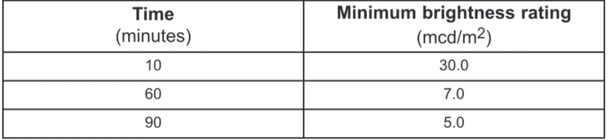
PLM strips shall have a minimum brightness rating (BR) of 30-7-5, which is the laboratory measurement of luminance at 10, 60, and 90 minutes, respectively (Table 1).
PLM installed in buildings should be tested in accordance with ISO 17398 [9], clause 7.11, with some modifications as stated in [3].
Table 1 Brightness rating for Photoluminescent material
3.1.2 Washability
The washability shall be tested in accordance with ASTM D 4828-1994 (2003) [10], Standard Test Methods for Practical Washability of Organic Coatings.
3.1.3 Toxicity
One test specimen (of each distinct product material) shall be tested in each of the flaming and non-flaming modes in accordance with Bombardier SMP 800-C (Rev. 4, 11/1/2000) Toxic Gas Generation Test [11] with some modifications as stated in [3].
3.1.4 Radioactivity
The radioactivity shall be tested in accordance with ASTM D 3648-2004, Standard Practices for the Measurement of Radioactivity [12].
3.1.5 Flame spread
Either one of the following two standards shall be followed:
The flame spread shall be tested in accordance with ASTM E 162-2002, Standard Test Method for Surface Flammability of Materials Using a Radiant Heat Energy Source [13] or, in accordance with ASTM D 635 2003, Standard Test Method for Rate of Burning and/or Extent and Time of Burning of Plastics in a Horizontal Position [14].
3.1.6 Abrasion resistance
This Guide does not specify minimum standards for abrasion resistance. For products that are to be applied to walking surfaces, it is recommended that building management consider: 1. The amount of traffic in the stairs by building occupants, and
2. The products' durability and resistance to abrasion.
4
Time
(minutes)
Minimum brightness rating
(mcd/m
2)
10 30.0
60 7.0
For instance, certain thin films and paints may be sufficient where the stairs are alarmed and only used in emergencies. However, where the occupants use the stairs on a daily basis, more durable products should be specified. Ultimately, the building owner is responsible for maintaining the photoluminescent materials in accordance with Section 5.
3.1.7 Slip-resistance
Although this Guide does not specify minimum slip-resistance requirements for photoluminescent products installed on walking surfaces, PLM markings should be as slip-resistant as the minimum standard that is applicable to the building in which they are being installed. Ideally, the slip resistance of the PLM should not be less than the slip resistance of the existing surface on which the PLM is to be installed. However, depending on the design of the stair nosing product, an adjacent, slip-resistant strip may be used to compensate for a strip of PLM that is less slip-resistant. . Evidence and approval of the slip-resistance capability of the installation may be provided by demonstration via a mock-up assembly as described in Section 4.4. Some guidance on determination of slip resistance is provided in ASTM D2047 [15].
3.1.8 Activating illumination
The illumination that energizes and charges the PLM needs to be capable of ensuring sufficient illumination. The following tests are required for activating illumination:
Laboratory testing:
To obtain the required BR as required in Section 3.1.1, the New York City Building Code Reference Standard 6-1 2005 [3] requires that the activating illumination be in accordance with ISO 17398 [9], clause 7.11, with some modifications as stated in [3].
In-situ testing:
• This Guide does not recommend the use of lower-performing photoluminescent products for brightly-lit environments, or the use of higher-performing photoluminescent products for grandfathered lighting environments. Therefore, prior to choosing a PLM product, owners are encouraged to conduct a survey of existing lighting conditions to ensure adequate performance for the particular installation.
• The Guide requires continuous illumination of corridors, exits and any other areas where PLM markings are situated. These areas shall be provided with a minimum of 10 lux of fluorescent illumination for not less than 60 minutes prior to periods when the building is occupied.
3.1.9 Contrasting colours
This Guide does not specify minimum standards for contrasting colours. Photoluminescent signage shall provide sufficient contrast between the symbols on the sign and the background of the sign to maintain visual characteristics. Contrasting colors allows the symbols to be depicted clearly. For example, in Figure 1, there should be sufficient contrast between the safety green [16] dark-coloured ”running-man” symbol compared to the light-coloured photoluminescent background of the sign.
Figure 1: Directional sign with the “running man”
3.2 Non-mandatory items
3.2.1 Dissimilar luminance levels within the same environment
It is neither necessary nor possible to require that photoluminescent products in the same environment emit identical luminance levels; many factors, including the distance to the activating light source, the angle of incidence and shadows, will result in different luminance levels for identical photoluminescent products placed in the same stairway. Variations in actual luminance are expected in the same environment. However, variations should be minimized and large variances in brightness ratings within the same environment should be avoided.
3.2.2 Adhesives
This Guide does not specify the adhesives to be used. The adhesive should be long-lasting and be capable of adhering to surfaces that might be porous, uneven, or subject to temperature or humidity variation. The manufacturers’ recommendations for surface preparation, priming and special coatings (if required) must be followed.
In addition, the adhesive should meet environmental requirements for cleanup and gaseous emissions.
Acceptability of adhesives that do not comply with the manufacturers' best practice should be demonstrated using mock-up assemblies as described in Section 4.4.
3.3
Need for demonstrating compliance with required
certifications
All photoluminescent markings for exit stairways shall be tested by an independent laboratory to certify compliance with the following requirements:
1. Brightness rating; 2. Washability; 3. Toxicity; 4. Radioactivity; 5. Flame spread; and 6. Activating illumination.
The test report shall include, as a minimum, the following information: 1. Manufacturer (name, address, phone, fax);
2. Specimen description (clear item identification to make specimens traceable to manufacturer's production batch code);
3. Date of testing;
4. Instrument parameters, photometer serial number and the expiry date of calibration; 5. Test methods (standards and/or procedures used);
6. Test results;
7. Name and title of tester; 8. Signature of tester; 9. Test location; and
10. Identification of testing company (full name, address, phone, fax).
3.4 PLM labelling
All approved materials shall be visibly labelled and identified with the model number in a minimum of 6-point type with at least one such identification on each piece of material installed. However, labelling is not required for pieces of material less than 300 mm in length that are placed in immediate proximity to a piece of the same product that is labelled. Products may include supplemental identifying information such as the manufacturer’s name and trade name.
4.
INSTALLATION/LOCATIONS
OF PLM MARKINGS
PLM markings should be provided to identify the entry points to the emergency exit doors on each floor. An exit path marking system should be installed in all stairways that could be a means of egress. The recommended installation is based on study findings conducted by NRC and PWGSC [4] and [5].
4.1 Exit doors at exit stairway shafts
Markings are required on:
1) doors opening to “exits” or “exit passageways” to an exit stair shaft;
2) doors opening to “corridors” where such “corridors” act as required “exit passageways” connecting two “vertical exits”, and
3) doors serving as “horizontal exits”. All such doors, other than intermediate or final exit doors, should be marked in compliance with 4.1.1 of this Guide. Intermediate and final exit doors should comply with 4.2.7 of this Guide.
Such marking is not required for main entrance-exit doors.
4.1.1 Exit signs
The entry point of exit doors at exit stairway shafts should be marked with a PLM door exit sign made in safety green, with the emergency exit symbol (running man) and an arrow (see Figure 1). The top of the sign should not be higher than 450 mm above the finished floor. The sign should be installed either on the door itself, or on the wall surface directly adjacent to the door on the latch-side. See Figure 2.
1- For the door-mounted option, the vertical centerline of the sign should be centered with the door, or should be in the half of the door, either the right or left, that contains the latch. In case of double-doors, both doors should be marked and the signs should be in the center of the doors. For door-mounted signs, arrows may be omitted.
2- For the wall-mounted option, the sign should be mounted on the wall surface directly adjacent to the latch-side of the door, as close as practicable to the door but in no case more than 150 mm from the door to the edge of the sign. In the case of double-doors, signs should be placed on the wall surface directly adjacent to the hinge-sides of both doors. Where the wall surface directly adjacent to the latch side is too narrow to accommodate the sign, the door-mounted option is preferred, but the sign may be placed on an adjacent perpendicular wall. Arrows are mandatory for wall-mounted signs.
4.1.2 Hardware (knobs, etc.)
Door handles or opening devices on emergency exit doors should be highlighted with PLM. Doorknobs and latches should be marked by placing a 100 x 100 mm piece of PLM behind the hardware or by applying a strip of PLM directly to push-pads, bars or panic hardware (see Figure 2).
4.1.3 Doorframes
The entire perimeter of doorframes of exit doors should be marked with strips of PLM not less than 25 mm in width (see Figure 2).
4.1.4 Identification sign for floor and stair name (See also 4.2.8-1) [17]
The floor number and stairway name should be mounted permanently on the wall at the latch side of the door to an exit stair shaft.
4.2 Exit stairs
Minimum requirements for exit stairs include markings within “vertical exits” (e.g. stairway, ramp), horizontal extensions in “vertical exits” (e.g. extended landing or corridor within a stairway), “horizontal exits” (e.g. bridge or tunnel between two buildings), “supplemental vertical exits” (e.g. stairway or ramp from an area of refuge), and “exit passageways” (e.g. passage leading from a yard or court to an exterior space). Such markings are not required in “street level lobbies”, “exterior stairs”, or “exterior balconies”.
8
Existing illuminated exit sign as may be required
by building code Doorframe markings (4.1.3) Hardware markings (4.1.2) 450 mm 150 mm Identification sign (4.1.4) 450 mm CL CL
Vertical centerline of sign centered with door or located in half of door containing latches (4.1.1)
A5
A5
4.2.1 Steps
The entire horizontal leading edge of each step should be marked with a solid and continuous strip of PLM. The dimensions, distances and locations should be consistent and uniform throughout the same exit as shown in Figure 3.
The width of the strips, measured horizontally should be:
• Maximum: 50 mm • Minimum: 25 mm
The strips should extend for the full width of each step.
The placement of the strips on the leading edge of the step should be: • Maximum: 13 mm from the leading edge of the step
• Minimum: 0 mm from the leading edge of the step.
The installation of PLM markings must not result in tripping or slipping hazards.
4.2.2 Leading edges of landings
The leading edge of all landings (for example the platforms at the top of stairs) should be marked in a consistent and uniform manner throughout a given exit. Leading edge markings should follow the same requirements as for the steps in 4.2.1 in size and location so that they are consistent with the strips on the steps, and extend the full length of the leading edge of the landing (see Figure 4).
9 0 mm min. 13 mm max. 25 mm min. 50 mm max. Photoluminescent strip Photoluminescent strip Same width as used on steps Same width as used on steps or 0 Same width as used on steps Photoluminescent strip Same width as used on steps Same width as used on steps or 0 Same width as used on steps
Figure 4: Marking on leading edge of landing
4.2.3 Handrails
All handrails and handrail extensions should be marked with a solid and continuous strip of PLM. The dimensions, distances and locations should be consistent and uniform throughout the same exit (see Figure 5).
The minimum width of the strip should be 25 mm. The strip should be placed at least on the top surface of all handrails along their entire lengths and include handrail extensions, and newel post caps.
Where handrails or handrail extensions bend or turn corners, PLM strips should be as continuous as
practicable and no discontinuity should be greater than 100 mm.
In existing buildings where handrail material or design makes it difficult to apply PLM on the top surface, a PLM strip at least 90 mm wide may be placed behind the handrail to silhouette it.
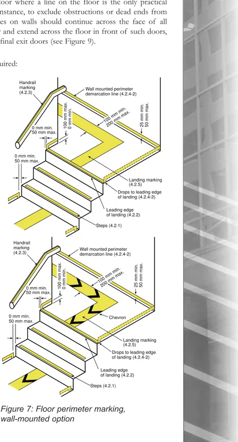
4.2.4 Floor perimeter demarcation lines
Floor perimeter demarcation lines are intended to outline the egress path by providing pathway marking lines on both sides of the path (see Figure 6 and Figure 7). Stair landings and other parts of the egress route should be provided with floor perimeter demarcation lines. The lines should be solid and continuous 25 to 50 mm-wide strips of PLM. The continuity of the demarcation lines may be interrupted to accommodate obstructions such as conduits, mouldings, corners or bends, but discontinuities should not exceed 100 mm. The dimensions, distances and locations should be uniform and consistent throughout the same exit. Demarcation lines should be located on the floor, or on the walls/vertical surface, or a combination of the two, as follows:
1. Floor-mounted option: Perimeter demarcation lines may be located on the floor, and should be placed as close as practicable to the wall, and should extend to within 50 mm of the markings on the leading edge of landings (see Figure 6). Where an obstruction (such as a standpipe) is located within the egress path, the demarcation line may extend across the floor so that the obstruction is outside of the outlined area. Demarcation lines
10
Handrail marking (4.2.3)
Floor mounted perimeter demarcation line (4.2.4-1) Leading edge of landing (4.2.2) Steps (4.2.1) 25 mm min. 50 mm max. Landing marking (4.2.5) 0 mm min. 50 mm max. 0 mm min. 50 mm max. 100 mm min. 200 mm max. Chevron Handrail marking (4.2.3)
Floor mounted perimeter demarcation line (4.2.4-1) Leading edge of landing (4.2.2) Steps (4.2.1) 25 mm min. 50 mm max. Landing marking (4.2.5) 0 mm min. 50 mm max. 0 mm min. 50 mm max. 100 mm min. 200 mm max.
Figure 6: Floor perimeter marking, floor-mounted option
Figure 5: Handrail marking 25 mm min. photoluminescent strip As close as practicable; 100 mm max. As close as practicable
on floors should continue across the floor in front of all doors, except in front of intermediate and final exit doors (see Figure 9).
2. Wall-mounted option: Perimeter demarcation lines may be located on the wall with the bottom edge no more than 100 mm above the finished floor. At the top or bottom of stairs, demarcation lines should drop vertically to the floor within 50 mm of the step or landing edge (see Figure 7). Demarcation lines on walls should transition vertically to the floor and then extend across the floor where a line on the floor is the only practical method of outlining the path (for instance, to exclude obstructions or dead ends from egress pathways). Demarcation lines on walls should continue across the face of all doors, or may transition to the floor and extend across the floor in front of such doors, except in front of intermediate and final exit doors (see Figure 9).
Perimeter demarcation lines are not required: 1. on the sides of steps; and
2. where an area is selected not to be outlined because it is not part of the egress path, for example an obstruction or dead end.
4.2.5 Landing markings
Landings, mid-landings, passageways or corridors within the stairway should be marked in the center-line with a continuous strip of PLM. The width of this solid strip of PLM should be not less than 100 mm and not more than 200 mm (see Figure 6 and Figure 7). The direction of movement could be indicated with a black or see-through chevron or arrow 25 mm wide at every meter and every change of direction (see Figure 6 and Figure 7). If chevrons are used, the same pattern should be used on all the landings in an exit. Alternatively, the landing marking should be a solid strip of PLM throughout the installation.
On the top floor of the stairway, the landing marking should start in the center-line of the exit door. On the exit floor, the landing marking should continue to the final exit door (see Figure 9).
11
Handrail marking
(4.2.3) Wall mounted perimeterdemarcation line (4.2.4-2)
Leading edge of landing (4.2.2) Steps (4.2.1) 0 mm min. 50 mm max. 25 mm min. 50 mm max. Landing marking (4.2.5) 0 mm min. 50 mm max. 100 mm min. 200 mm max. 100 mm max. 0 mm min.
Drops to leading edge of landing (4.2.4-2)
Handrail marking
(4.2.3) Wall mounted perimeterdemarcation line (4.2.4-2)
Leading edge of landing (4.2.2) Steps (4.2.1) 0 mm min. 50 mm max. 25 mm min. 50 mm max. Landing marking (4.2.5) 0 mm min. 50 mm max. 100 mm min. 200 mm max. 100 mm max. 0 mm min.
Drops to leading edge of landing (4.2.4-2) Chevron
Figure 7: Floor perimeter marking, wall-mounted option
4.2.6 Obstacles (e.g., pipes, hoses, etc.)
Obstacles at or below 1980 mm in height and projecting more than 100 mm into the egress path should be outlined with markings no less than 25 mm in width comprised of a pattern of alternating equal bands of photoluminescent material and black, with the alternating bands no more than 50 mm wide and angled at 45 degrees. Examples of such obstacles include standpipes, hose cabinets, wall projections, and restricted height areas (see Figure 8).
4.2.7 Final exit doors
Throughout this Guide, intermediate and final exit doors have the following meanings: • Intermediate exit door: when traveling in the egress direction, a door that leads from a
vertical exit, horizontal extension in a vertical exit, horizontal exit, supplemental vertical exit, or exit passageway, but does not lead directly to the exterior or to a street level lobby. • Final exit door: a door leading directly to the exterior or a street level lobby.
12
Figure 8: Obstacles and demarcation lines
Marking of obstacles (4.2.6)
Floor/wall mounted demarcation lines (4.2.4-1, 4.2.4-2)
1980 mm min. above finish floor
25 mm min. 50 mm max.
as closed as practicable
1980 mm min. above finish floor
25 mm min. 50 mm max. as closed as practicable
Figure 9: Intermediate and final exits
Existing illuminated exit sign as may be required
by building code
Door hardware markings (4.2.7) Door sign (4.2.7) Doorframe markings (4.2.7) FINAL EXIT SORTIE FINALE No perimeter floor/wall demarcation line at door (4.2.4)
Landing marking (4.2.5) Existing illuminated exit sign as may be required
by building code
Door hardware markings (4.2.7) Door sign (4.2.7) Doorframe markings (4.2.7) FINAL EXIT SORTIE FINALE No perimeter floor/wall demarcation line at door (4.2.4)
An intermediate exit door should have a PLM exit sign as described in 4.1.1. At the final exit door, a door-mounted sign should contain text in sans serif letters. Examples of such texts are “FINAL EXIT”, or “EXIT THROUGH LOBBY” or “EXIT TO STREET”, or “EXIT TO CHAMBERS STREET”, etc (see Figure 9). Signs with text should meet applicable regulations regarding bilingual signage. These signs, exit sign or final exit sign, should be placed in the center of the door at 1200 to 1600 mm from the floor [17].
Door hardware on all intermediate and final exit doors should be marked with no less than 400 mm2of PLM. This marking should be located behind, immediately adjacent to, or on the door handle and/or escutcheon. On panic hardware, the PLM marking should be no less than 25 mm wide for the entire length of the actuating bar or touchpad. Hardware markings may include safety green graphics such as arrows indicating door handle turning directions, the emergency egress symbol (running man, see Figure 1), the word “PUSH”, and similar egress-related symbols provided a minimum 100 X 100 mm of PLM is maintained. The top and sides of the door frame of all intermediate and final exit doors should be marked with a solid and continuous 25 mm to 50 mm wide strip of PLM. Gaps in the continuity of doorframe markings are permitted where a line is fitted into a corner or bend, but should be as small as practicable and in no case greater than 25 mm . Where a door moulding does not provide enough flat surface on which to locate the strip, the strips may be located on the wall surrounding the frame. The dimensions, distances and locations of the required markings should be consistent and uniform on all doors on the route to the exterior of the building.
4.2.8 Additional markings
1. Floor number and stairway identification: PLM signs should be placed adjacent to the exit door inside the stairway to identify the floor number and the stairway number and/or name. Such signs should contain sans serif letters at least 45 mm and should be located at 1200 mm to 1600 mm above the floor [17].
2. Directional signage at transfer levels: PLM directional signs should be provided in safety green, including the word “Transfer level” or “Crossover floor”, should be posted next to the exit door wherever re-entry to a floor or transfer to another means of egress is permitted. The sign should be located 1200 to 1600 mm above the floor and the lettering should be sans serif letters at least 25 mm high.
3. “Not An Exit” sign: PLM signs should be placed on doors along the egress path that lead to dead ends (mechanical rooms, storage closets, etc.) Such signs should contain black or red sans serif letters at least 25 mm high reading "NOT AN EXIT" and be placed on the door at 1200 mm to 1600 mm above the floor.
4. “No Roof Access” sign: In buildings where roof access is not possible for building occupants, PLM signs including the words “NO ROOF ACCESS” should be placed on the mid-landing wall 1200 to 1600 mm above the floor every 3 floors and on every floor for the 5 top floors of the stairway. The sign should contain black or red sans serif letters at least 25 mm high reading “NO ROOF ACCESS”.
5. Where direction is not clear, additional signage should be provided following the general guidelines in 4.2.8.
6. Signs containing words should be provided in both official languages according to regulation.
4.3 Consideration of attachment of material for reuse
PLM marking is usually custom made and installed with adhesives that provide for a permanent installation. It is possible to install some of the signs and pathway marking lines in tracks or profiles that could allow removal of the PLM and its reuse in another location. It could be expected, however, that installations using a system of tracks or profiles might be more costly than a permanent installation.
4.4 Use of mock-up assemblies for approval of PLM installation
Mock-ups are full-size assemblies constructed to demonstrate PLM marking and sign compliance with requirements and to provide training for installation trades. Mock-ups should prove the adhesion of PLM to its substrate and demonstrate the slip resistance of the material. These assemblies should be constructed in a timely fashion to allow a minimum of 24 hours for inspection of mock-up before installation work proceeds
When accepted, a mock-up will demonstrate the minimum standard of quality required for the installation of PLM markings. An approved mock-up may, at the discretion of the responsible authority, remain as part of finished work or may be required to be removed when no longer required.
5. MAINTENANCE OF PLM MARKINGS
5.1 Inspections
Building owners should keep the required photoluminescent signs and markings in good repair. At a minimum, owners should, every 12 months, perform a visual inspection of the signs and markings with the normal lighting turned on to identify any missing marking, and a visual inspection with the lights turned off to identify deficiencies. Illuminating sources should be checked for functionality.
5.2 Replacement and repair
Signs and markings that are deteriorated, discoloured, damaged, loose, or that show signs of wear or missing labels should be scheduled for immediate replacement or repair. Any missing or failed lamps and luminaires should be immediately repaired or replaced.
5.3 Maintenance record keeping
A log of PLM inspections, including the results and any corrective measures taken, should be recorded and kept for a minimum of 5 years on the premises for inspection by the building management and the fire department. The log should contain the inspection dates and the name and signatures of inspectors. In addition, all modifications, results of inspection/maintenance and any other pertinent information should be recorded in the logbook.
5.4 Decreased performance due to dirt on material
Situations may arise where markings and signs become dirty, especially in winter seasons, particularly markings on floors. Periodic checking and cleaning should be done to insure the performance of the PLM in the event of an emergency.. Where applicable, section 3.14 of the Handbook of Occupational Safety and Health [7] should be used.
6. REFERENCES
1. Krokeide, G., 1988, “An Introduction to Luminous Escape Systems”, Safety in the Built Environment, pp. 134-147.
2. Amy, D. James, Escape from New York – The Use of Photoluminescent Pathway-marking Systems in High-Rise Office Buildings, Emerging Trends eNewsletter, Issue 8, December 2006, Society of Fire Protection Engineers,
http://www.fpemag.com/archives/enewsletter.asp?i=16
3. New York City Reference Standard 6-1 and RS 6-1 A, 2005, Photoluminescent Exit Path Markings, NYC Law 26, New York City Building Code, U.S.A.
http://home2.nyc.gov/html/dob/downloads/pdf/rs_6-1.pdf
4. Proulx, G., Bénichou, N., Hum, J.K., Restivo, K.N., 2007, Evaluation of the
Effectiveness of Different Photoluminescent Stairwell Installations for the Evacuation of Office Building Occupants, Research Report #232, Institute for Research in Construction, National Research Council Canada, pp. 77, (URL: http://irc.nrc-cnrc.gc.ca/pubs/rr/rr232/)
5. Proulx, G., Tiller, D.K., Kyle, B.R., Creak, J., 1999, Assessment of Photoluminescent Material During Office Occupant Evacuation, Internal Report #774, Institute for Research in Construction, National Research Council Canada, pp. 38, URL: http://irc.nrc-cnrc.gc.ca/pubs/ir/ir774/
6. National Building Code of Canada, 2005, National Research Council Canada
7. COSH, 1994, Handbook of Occupational Safety and Health, Fifth Edition, Treasury Board of Canada Secretariat, Human Resources Management Office, Occupational Safety and Health Chapter 3-1 Standard for fire safety planning and fire emergency organization, Ottawa, Canada
http://www.tbs-sct.gc.ca/pubs_pol/hrpubs/tbm_119/chap3_1-1_e.asp.
8. ISO 16069, 2004, Graphical symbols – Safety signs – Safety way guidance systems (SWGS).
9. ISO 17398, 2004, Safety Colours and safety signs - Classification, performance and durability of safety signs.
10. ASTM D 4828 – 94,2003: Standard Test Methods for Practical Washability of Organic Coatings.
11. Bombardier SMP 800-C, 2000, (Rev. 4, 11/1/2000) Toxic Gas Generation Test. 12. ASTM D 3648, 2004: Standard Practices for the Measurement of Radioactivity.
13. ASTM E 162, 2002: Standard Test Method for Surface Flammability of Materials Using a Radiant Heat Energy Source.
14. ASTM D 635, 2003: Standard Test Method for Rate of Burning and/or Extent and Time of Burning of Plastics in a Horizontal Position.
15. ASTM D2047, 1993, Standard Test Method for Static Coefficient of Friction of Polish-Coated Floor Surfaces as Measured by the James Machine.
16. ISO 7010, 2003, Graphical Symbols – Safety Colours and Safety Signs.
17. Arthur, P., Passini, R., 1992, Wayfinding: People, Signs, and Architecture, Mc-Graw-Hill Book Company.